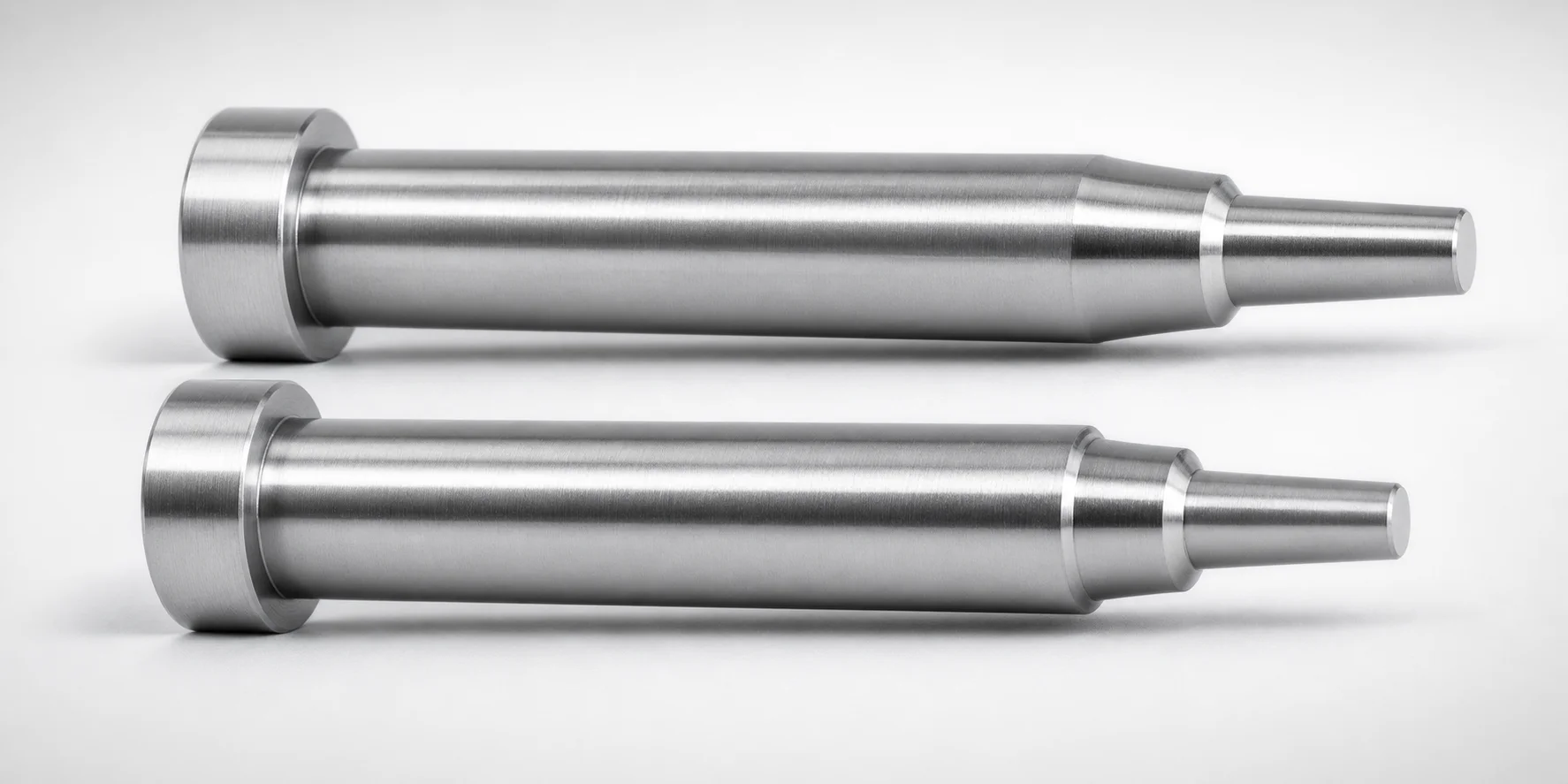
JIS Standard Steel Two-Step Core Pins Flat Sides
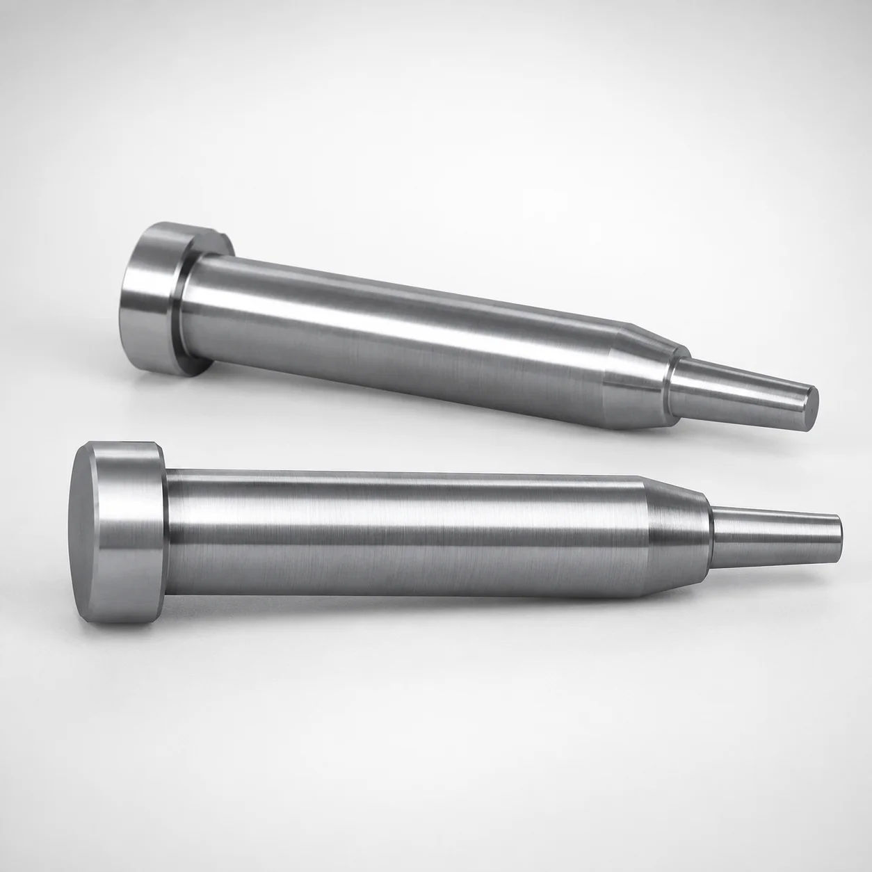
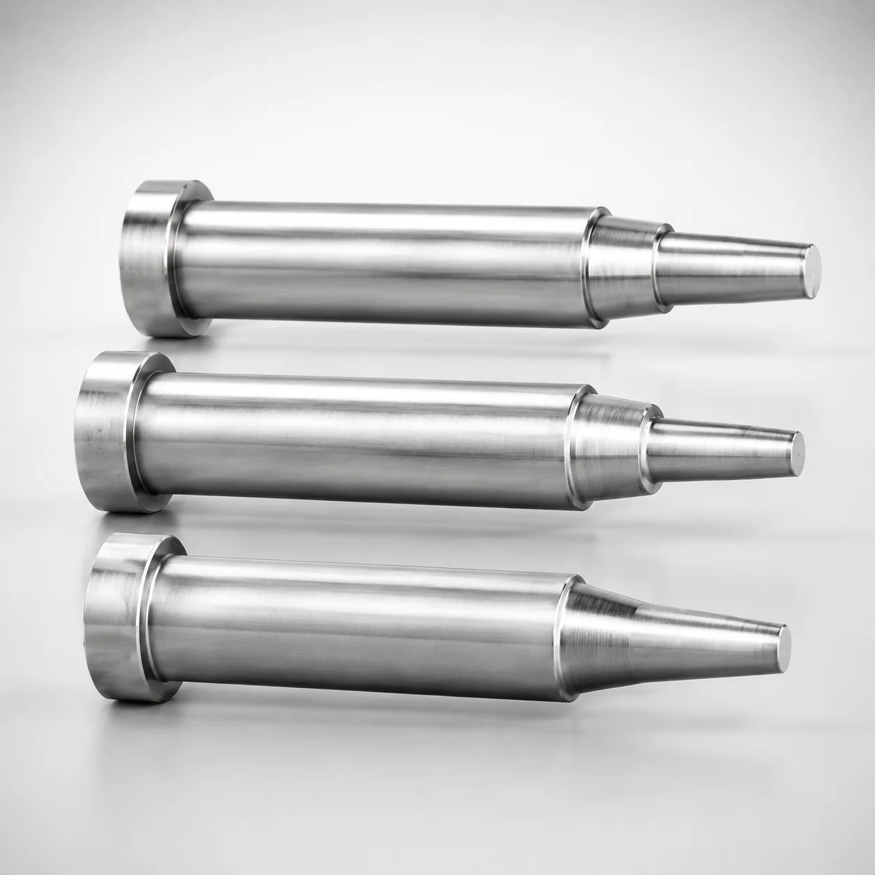
Two-step core pins (Hardened steel) with flat-sides design provide stable positioning for consistent ejection in precision mold builds. The two-step profile improves guidance while supporting controlled tip geometry.
- Two-step shape with tight tip gradient tolerance ±0.005 for dependable positioning
- Hardened steel construction supports durable wear resistance during repeated mold cycles
- L dimension tolerance +0.01/0 for accurate core fit in mold assembly
- Built for precision tooling applications requiring secure alignment and repeatable results
Specifications
1908 configurations available
| Material | D/P (Shaft Diameter) (mm) | First Step Shape | Second Step Shape | A (Type of the first step diameter) (mm) | C (First step shape taper width) (mm) | E (Tip diameter) (mm) | F (Bearing bore length) (mm) | FC (Makes F dimension shorter than F min) (mm) | G (C chamfering width of the second step shape) (mm) | J (Type of the second step) (mm) | L (L dimension) (mm) | Q (Second step shape R chamfering) (mm) | R (First step type R) (mm) | V (Type of the second step) (mm) | Dimension Y (mm) | type |
|---|---|---|---|---|---|---|---|---|---|---|---|---|---|---|---|---|
| SKH51 | 1 | CA | A | - | - | 0.5 ~ 0.98 | 12 ~ 149 | - | - | - | 6.5 ~ 100 | - | - | 0.51 ~ 0.99 | 12.5 ~ 149.5 | - |
| SKH51 | 1 | CA | A | - | - | 0.5 ~ 0.98 | - | 5 ~ 12.99 | - | - | 6.5 ~ 100 | - | - | 0.51 ~ 0.99 | 12.5 ~ 149.5 | - |
| SKH51 | 1.5 | CA | A | - | - | 0.5 ~ 1.48 | 12 ~ 149 | - | - | - | 6.5 ~ 100 | - | - | 0.5 ~ 1.49 | 12.5 ~ 149.5 | - |
| SKH51 | 1.5 | CA | A | - | - | 0.5 ~ 1.48 | - | 5 ~ 12.99 | - | - | 6.5 ~ 100 | - | - | 0.5 ~ 1.49 | 12.5 ~ 149.5 | - |
| SKH51 | 2 | CA | A | - | - | 0.7 ~ 1.99 | 12 ~ 149 | - | - | - | 6.5 ~ 100 | - | - | 0.7 ~ 1.99 | 12.5 ~ 149.5 | - |
| SKH51 | 2 | CA | A | - | - | 0.7 ~ 1.99 | - | 5 ~ 12.99 | - | - | 6.5 ~ 100 | - | - | 0.7 ~ 1.99 | 12.5 ~ 149.5 | - |
| SKH51 | 2.5 | CA | A | - | - | 0.7 ~ 2.49 | 12 ~ 149 | - | - | - | 6.5 ~ 100 | - | - | 0.7 ~ 2.49 | 12.5 ~ 149.5 | - |
| SKH51 | 2.5 | CA | A | - | - | 0.7 ~ 2.49 | - | 5 ~ 12.99 | - | - | 6.5 ~ 100 | - | - | 0.7 ~ 2.49 | 12.5 ~ 149.5 | - |
| SKH51 | 3 | CA | A | - | - | 1 ~ 2.99 | 12 ~ 149 | - | - | - | 6.5 ~ 100 | - | - | 1 ~ 2.99 | 12.5 ~ 149.5 | - |
| SKH51 | 3 | CA | A | - | - | 1 ~ 2.99 | - | 5 ~ 12.99 | - | - | 6.5 ~ 100 | - | - | 1 ~ 2.99 | 12.5 ~ 149.5 | - |
| SKH51 | 3.5 | CA | A | - | - | 1 ~ 3.49 | 12 ~ 149 | - | - | - | 6.5 ~ 100 | - | - | 1 ~ 3.49 | 12.5 ~ 149.5 | - |
| SKH51 | 3.5 | CA | A | - | - | 1 ~ 3.49 | - | 5 ~ 12.99 | - | - | 6.5 ~ 100 | - | - | 1 ~ 3.49 | 12.5 ~ 149.5 | - |
| SKH51 | 4 | CA | A | - | - | 1 ~ 3.99 | 12 ~ 149 | - | - | - | 6.5 ~ 120 | - | - | 1 ~ 3.99 | 12.5 ~ 149.5 | - |
| SKH51 | 4 | CA | A | - | - | 1 ~ 3.99 | - | 5 ~ 12.99 | - | - | 6.5 ~ 120 | - | - | 1 ~ 3.99 | 12.5 ~ 149.5 | - |
| SKH51 | 4.5 | CA | A | - | - | 1.5 ~ 4.49 | 12 ~ 149 | - | - | - | 6.5 ~ 120 | - | - | 1.5 ~ 4.49 | 12.5 ~ 149.5 | - |
| SKH51 | 4.5 | CA | A | - | - | 1.5 ~ 4.49 | - | 5 ~ 12.99 | - | - | 6.5 ~ 120 | - | - | 1.5 ~ 4.49 | 12.5 ~ 149.5 | - |
| SKH51 | 5 | CA | A | - | - | 1.5 ~ 4.99 | 12 ~ 149 | - | - | - | 6.5 ~ 150 | - | - | 1.5 ~ 4.99 | 12.5 ~ 149.5 | - |
| SKH51 | 5 | CA | A | - | - | 1.5 ~ 4.99 | - | 5 ~ 12.99 | - | - | 6.5 ~ 150 | - | - | 1.5 ~ 4.99 | 12.5 ~ 149.5 | - |
| SKH51 | 5.5 | CA | A | - | - | 1.5 ~ 5.49 | 12 ~ 149 | - | - | - | 6.5 ~ 150 | - | - | 1.5 ~ 5.49 | 12.5 ~ 149.5 | - |
| SKH51 | 5.5 | CA | A | - | - | 1.5 ~ 5.49 | - | 5 ~ 12.99 | - | - | 6.5 ~ 150 | - | - | 1.5 ~ 5.49 | 12.5 ~ 149.5 | - |
| SKH51 | 6 | CA | A | - | - | 2 ~ 5.99 | 12 ~ 149 | - | - | - | 6.5 ~ 150 | - | - | 2 ~ 5.99 | 12.5 ~ 149.5 | - |
| SKH51 | 6 | CA | A | - | - | 2 ~ 5.99 | - | 5 ~ 12.99 | - | - | 6.5 ~ 150 | - | - | 2 ~ 5.99 | 12.5 ~ 149.5 | - |
| SKH51 | 6.5 | CA | A | - | - | 2 ~ 6.49 | 12 ~ 149 | - | - | - | 6.5 ~ 150 | - | - | 2 ~ 6.49 | 12.5 ~ 149.5 | - |
| SKH51 | 6.5 | CA | A | - | - | 2 ~ 6.49 | - | 5 ~ 12.99 | - | - | 6.5 ~ 150 | - | - | 2 ~ 6.49 | 12.5 ~ 149.5 | - |
| SKH51 | 7 | CA | A | - | - | 2 ~ 6.99 | 12 ~ 149 | - | - | - | 6.5 ~ 150 | - | - | 2 ~ 6.99 | 12.5 ~ 149.5 | - |
| SKH51 | 7 | CA | A | - | - | 2 ~ 6.99 | - | 5 ~ 12.99 | - | - | 6.5 ~ 150 | - | - | 2 ~ 6.99 | 12.5 ~ 149.5 | - |
| SKH51 | 8 | CA | A | - | - | 2 ~ 7.99 | 12 ~ 149 | - | - | - | 6.5 ~ 150 | - | - | 2 ~ 7.99 | 12.5 ~ 149.5 | - |
| SKH51 | 8 | CA | A | - | - | 2 ~ 7.99 | - | 5 ~ 12.99 | - | - | 6.5 ~ 150 | - | - | 2 ~ 7.99 | 12.5 ~ 149.5 | - |
| SKH51 | 10 | CA | A | - | - | 2 ~ 9.99 | 12 ~ 149 | - | - | - | 6.5 ~ 150 | - | - | 2 ~ 9.99 | 12.5 ~ 149.5 | - |
| SKH51 | 10 | CA | A | - | - | 2 ~ 9.99 | - | 5 ~ 12.99 | - | - | 6.5 ~ 150 | - | - | 2 ~ 9.99 | 12.5 ~ 149.5 | - |
| SKH51 | 13 | CA | A | - | - | 2.5 ~ 12.99 | 12 ~ 149 | - | - | - | 6.5 ~ 150 | - | - | 2.5 ~ 12.99 | 12.5 ~ 149.5 | - |
| SKH51 | 13 | CA | A | - | - | 2.5 ~ 12.99 | - | 5 ~ 12.99 | - | - | 6.5 ~ 150 | - | - | 2.5 ~ 12.99 | 12.5 ~ 149.5 | - |
| SKH51 | 16 | CA | A | - | - | 2.5 ~ 15.99 | 12 ~ 149 | - | - | - | 6.5 ~ 150 | - | - | 2.5 ~ 15.99 | 12.5 ~ 149.5 | - |
| SKH51 | 16 | CA | A | - | - | 2.5 ~ 15.99 | - | 5 ~ 12.99 | - | - | 6.5 ~ 150 | - | - | 2.5 ~ 15.99 | 12.5 ~ 149.5 | - |
| SKH51 | 20 | CA | A | - | - | 5 ~ 19.99 | 28 ~ 149 | - | - | - | 6.5 ~ 13.99 | - | - | 5 ~ 19.99 | 28.5 ~ 149.5 | - |
| SKH51 | 20 | CA | A | - | - | 5 ~ 19.99 | - | 5 ~ 27.99 | - | - | 6.5 ~ 13.99 | - | - | 5 ~ 19.99 | 28.5 ~ 149.5 | - |
| SKH51 | 20 | CA | A | - | - | 5 ~ 19.99 | 28 ~ 149 | - | - | - | 30 ~ 150 | - | - | 5 ~ 19.99 | 28.5 ~ 149.5 | - |
| SKH51 | 20 | CA | A | - | - | 5 ~ 19.99 | - | 5 ~ 27.99 | - | - | 30 ~ 150 | - | - | 5 ~ 19.99 | 28.5 ~ 149.5 | - |
| SKH51 | 1 | CA | B | - | - | 0.5 ~ 0.98 | 12 ~ 149 | - | - | 0.5 ~ 0.98 | 6.5 ~ 100 | - | - | 0.51 ~ 0.99 | 12.5 ~ 149.5 | - |
| SKH51 | 1 | CA | B | - | - | 0.5 ~ 0.98 | - | 5 ~ 12.99 | - | 0.5 ~ 0.98 | 6.5 ~ 100 | - | - | 0.51 ~ 0.99 | 12.5 ~ 149.5 | - |
| SKH51 | 1.5 | CA | B | - | - | 0.5 ~ 1.48 | 12 ~ 149 | - | - | 0.5 ~ 1.45 | 6.5 ~ 100 | - | - | 0.55 ~ 1.49 | 12.5 ~ 149.5 | - |
| SKH51 | 1.5 | CA | B | - | - | 0.5 ~ 1.48 | - | 5 ~ 12.99 | - | 0.5 ~ 1.45 | 6.5 ~ 100 | - | - | 0.55 ~ 1.49 | 12.5 ~ 149.5 | - |
| SKH51 | 2 | CA | B | - | - | 0.7 ~ 1.98 | 12 ~ 149 | - | - | 0.7 ~ 1.95 | 6.5 ~ 100 | - | - | 0.75 ~ 1.99 | 12.5 ~ 149.5 | - |
| SKH51 | 2 | CA | B | - | - | 0.7 ~ 1.98 | - | 5 ~ 12.99 | - | 0.7 ~ 1.95 | 6.5 ~ 100 | - | - | 0.75 ~ 1.99 | 12.5 ~ 149.5 | - |
| SKH51 | 2.5 | CA | B | - | - | 0.7 ~ 2.48 | 12 ~ 149 | - | - | 0.7 ~ 2.45 | 6.5 ~ 100 | - | - | 0.75 ~ 2.49 | 12.5 ~ 149.5 | - |
| SKH51 | 2.5 | CA | B | - | - | 0.7 ~ 2.48 | - | 5 ~ 12.99 | - | 0.7 ~ 2.45 | 6.5 ~ 100 | - | - | 0.75 ~ 2.49 | 12.5 ~ 149.5 | - |
| SKH51 | 3 | CA | B | - | - | 1 ~ 2.98 | 12 ~ 149 | - | - | 1 ~ 2.98 | 6.5 ~ 100 | - | - | 0.95 ~ 2.99 | 12.5 ~ 149.5 | - |
| SKH51 | 3 | CA | B | - | - | 1 ~ 2.98 | - | 5 ~ 12.99 | - | 1 ~ 2.98 | 6.5 ~ 100 | - | - | 0.95 ~ 2.99 | 12.5 ~ 149.5 | - |
| SKH51 | 3.5 | CA | B | - | - | 1 ~ 3.48 | 12 ~ 149 | - | - | 1 ~ 3.45 | 6.5 ~ 100 | - | - | 0.95 ~ 3.49 | 12.5 ~ 149.5 | - |
| SKH51 | 3.5 | CA | B | - | - | 1 ~ 3.48 | - | 5 ~ 12.99 | - | 1 ~ 3.45 | 6.5 ~ 100 | - | - | 0.95 ~ 3.49 | 12.5 ~ 149.5 | - |
Product Guide
Application Scenarios+
Two-step core pins with flat guidance surfaces are commonly used in precision injection mold assemblies where repeatable ejection and stable alignment are critical. The flat sides help maintain rotational orientation of the core pin during setup and operation, reducing misalignment risk that can disturb the core-to-cavity relationship.
In automotive connector and sensor housing molds, the two-step profile provides controlled tip geometry and improved guidance as the core pin enters and exits the molded part. This supports consistent ejection across tight cycle windows, especially when the contact zone experiences frequent sliding.
For medical device housings and inspection-ready components, stable positioning reduces variability in feature formation near the pin interface. The hardened steel construction supports wear resistance under repeated molding cycles while maintaining dimensional stability.
When you need reliable ejection in high-precision electronics and small-diameter core builds, the variant’s tight L dimension tolerance (+0.01/0) and the specified tip gradient tolerance ±0.005 make it suitable for core fit and consistent guidance.
Material & Process Details+
This series is available in SKH51 and SKD61, both hardened steel options selected for durable core-pin performance under sliding contact. SKH51 is typically treated as an AISI M2 equivalent high-speed steel grade, known for strong wear resistance and good toughness balance in tool steels.
SKD61 corresponds to H13 equivalent hot-work tool steel, widely used where heat checking and thermal fatigue resistance matter in molding service.
- Heat treatment state: Hardened steel construction is specified for durable ejection and repeated cycles (exact hardness level is not provided in the input data).
- Wear vs. toughness trade-off: M2-class SKH51 generally emphasizes wear resistance at sliding interfaces, while H13-class SKD61 is often selected for more balanced high-temperature tooling durability.
- Manufacturing process: precision machining is followed by hardening and finishing to achieve the tight dimensional requirements such as the L tolerance (+0.01/0) and specified tip geometry tolerance.
Hardness (HRC): Not specified in the provided metadata.
Sizing & Selection Guide+
To select the correct two-step core pin size, match the required D/P (shaft diameter) first. This series supports D/P = 1 ~ 20 mm, so choose the diameter that corresponds to the core pin bore and functional sliding clearance in your mold.
Next, verify the axial length using L = 6.5 ~ 100 mm. The input data specifies a tight L dimension tolerance of +0.01 / 0, so ensure the pin length does not exceed your assembly’s available space while still meeting guidance depth requirements.
- Two-step geometry selection: Choose the first step shape from CA, CB, CC, CD, CE and the second step shape from A, B, C, D, E, then confirm the step diameters using A = 0.5 ~ 10 mm and E (tip diameter) = 0.5 ~ 5 mm.
- Step/feature dimensions: Confirm taper width C (given ranges including 0.1 ~ 0.2, 0.1 ~ 1, and an additional listed range), and tip/bearing-related widths such as G = 0.1 ~ 0.5.
- Fit considerations: Because L tolerance is strictly controlled and tip gradient is listed as ±0.005, validate that your core positioning and ejector alignment will not force the pin into binding during repeated cycles.
Where exact lengths or reduced versions are required, use the configurable FC option (ranges listed per configuration) to shorten F below the minimum.
Frequently Asked Questions
How do the tight L dimension tolerance (+0.01/0) and tip gradient tolerance (±0.005) affect core pin fit in stepped-core assemblies?+
The series is specified with L tolerance of +0.01/0 to support accurate core fit in the mold assembly. It also lists a tip gradient tolerance of ±0.005, which helps maintain controlled guidance at the pin’s tip during ejection.
In practice, this reduces variability in core engagement depth and helps prevent inconsistent contact that can lead to ejection-related misalignment.
Which material should I choose between SKH51 and SKD61 for a two-step core pin used in frequent sliding contact?+
The product supports SKH51 and SKD61 hardened steel options. SKH51 is generally considered an AISI M2 equivalent, emphasizing wear resistance for sliding interfaces. SKD61 is generally treated as H13 equivalent, commonly selected for tooling durability where thermal effects are present.
Select the grade based on whether your application is dominated by sliding wear (lean toward SKH51) or by thermal and cyclic durability needs (lean toward SKD61).
What shaft diameter (D/P) range is available, and how should I match it to the mold bushing or core hole?+
This series offers D/P = 1 ~ 20 mm. Choose the diameter that aligns with the core-pin bore and sliding clearance requirements of your mold assembly design.
Because the pins are hardened and produced for precision guidance, confirm that your core hole/bushing geometry supports smooth motion without binding under ejection loads.
How do I select the step geometry (first step shapes CA–CE and second step shapes A–E) for correct guidance?+
First step shapes are selectable from CA, CB, CC, CD, CE, and second step shapes from A, B, C, D, E. You then confirm the dimensional parameters tied to each geometry, including A (0.5 ~ 10 mm) for the first step diameter and E (0.5 ~ 5 mm) for the tip diameter.
Finally, verify taper/width-related settings such as C and chamfer dimensions like G to ensure the pin enters and guides the core interface correctly.
Can the bearing bore length (F) be adjusted below the minimum requirement using FC, and what does FC represent?+
The bearing bore length F is specified over multiple ranges (e.g., 12 ~ 149 and other listed banded options depending on configuration). The option FC is provided to make F dimension shorter than the minimum, with listed ranges such as 5 ~ 12.99 (and additional configuration-dependent ranges).
Use FC when your assembly requires extra clearance and you cannot meet the default minimum F while still maintaining the pin’s step guidance function.
Related Products
Need Custom Specifications?
Our engineering team can help with custom configurations, material selection, and volume pricing.