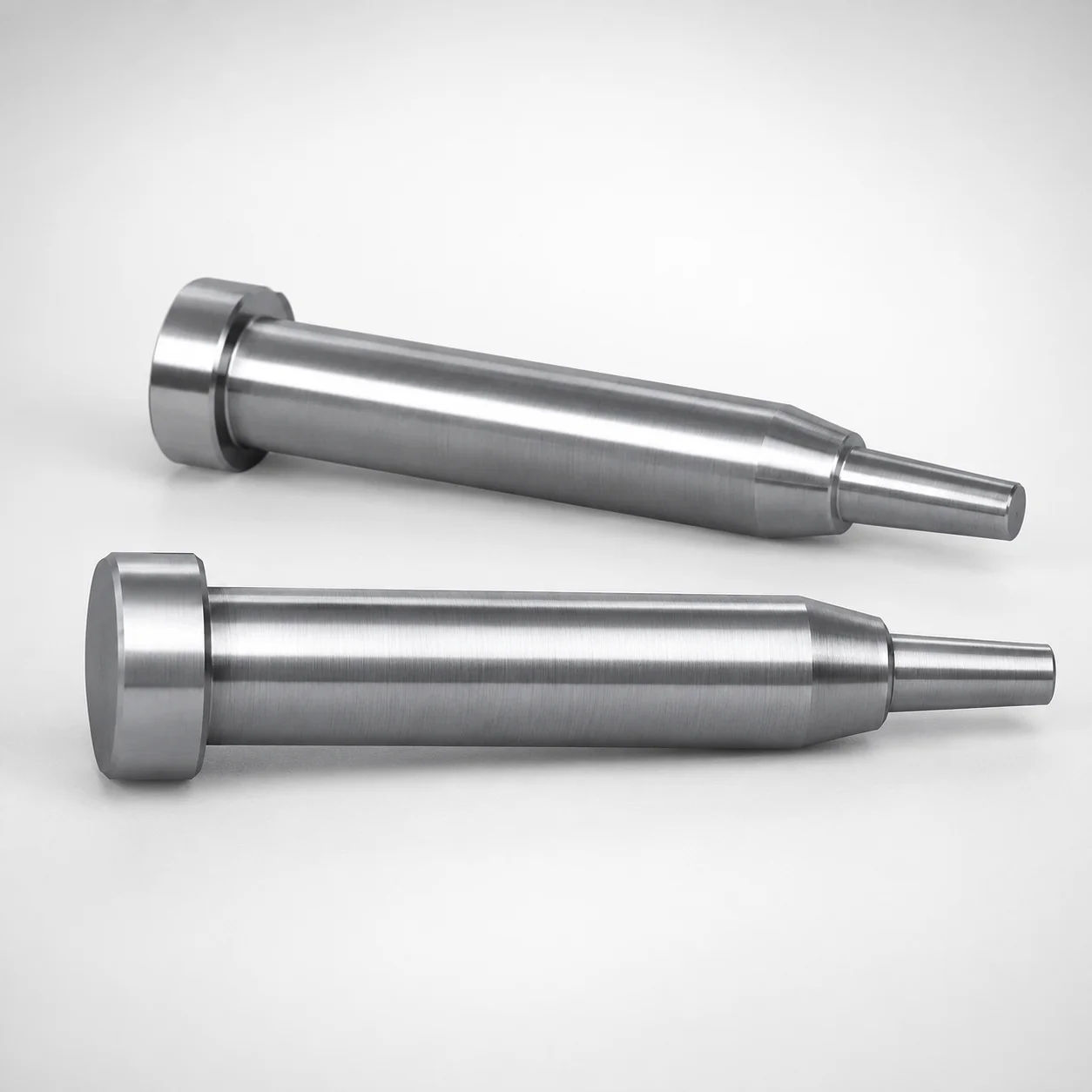
JIS Standard Steel Two-Step Core Pins Flat-Sided
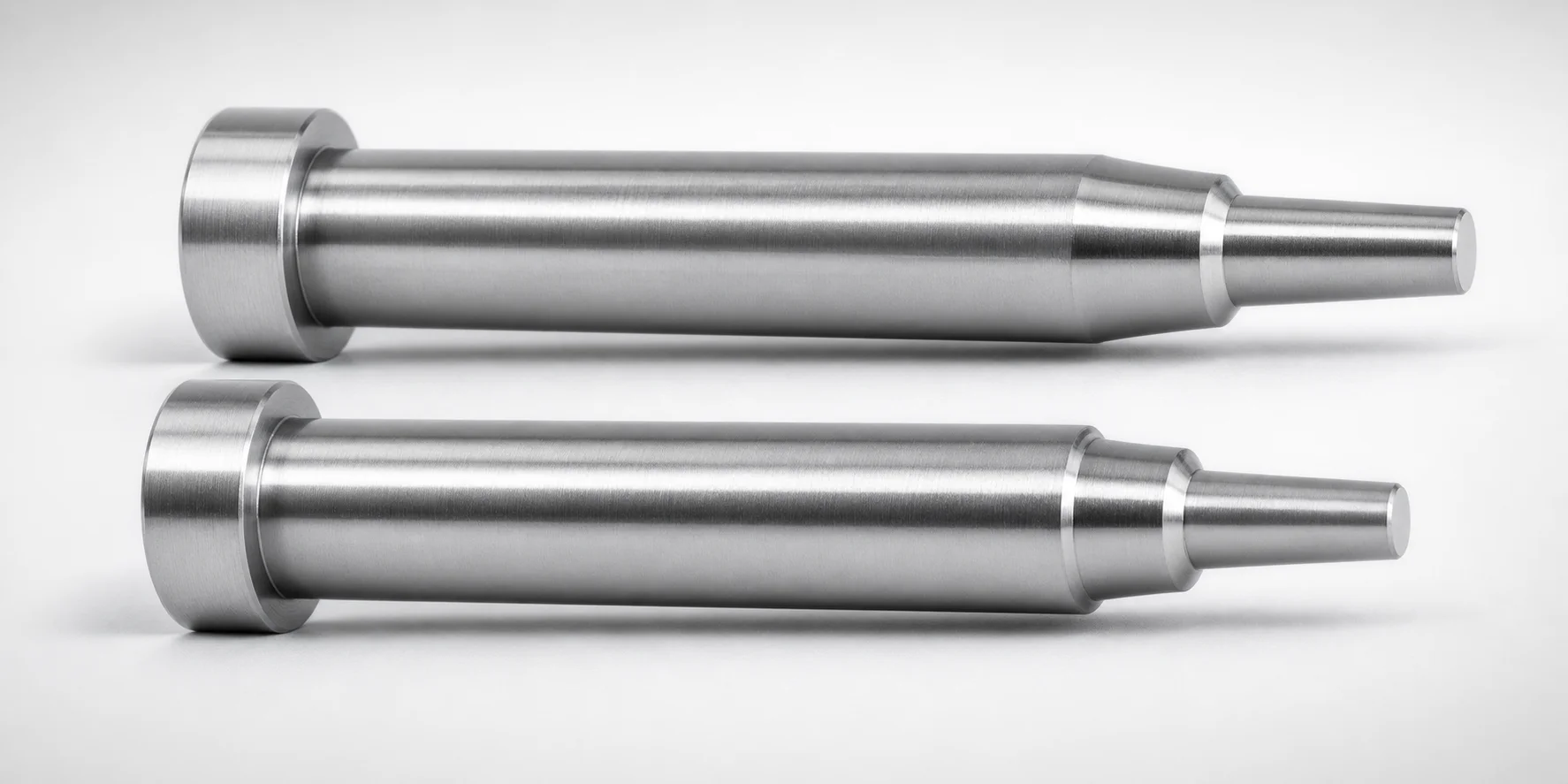
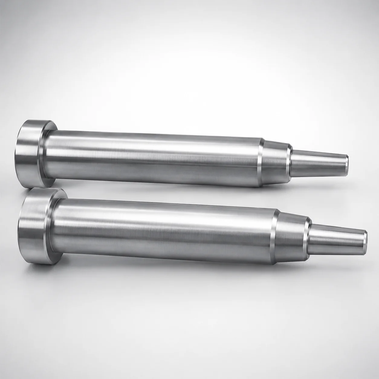
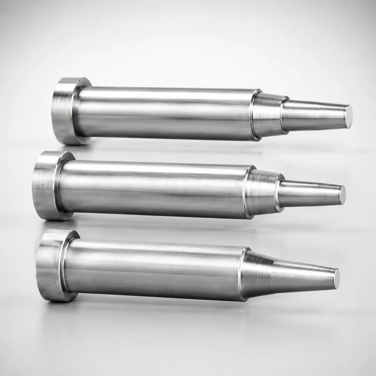
Two-step core pins (steel) with a flat-sided head are designed to prevent rotation and keep the core pin aligned during high-cycle mold operation. The two-step geometry supports controlled positioning for repeatable part ejection.
- Flat-sided anti-rotation head design stabilizes pin orientation for consistent ejection accuracy
- Built from hardened steel options for dependable wear resistance under repetitive mold contact
- Supports tight assembly performance with L dimension tolerance (+0.02/0)
- Used in precision injection and die molds requiring two-step core pin locating
Specifications
1828 configurations available
| Material | D/P (Shaft Diameter) (mm) | First Step Shape | Second Step Shape | A (Type of the first step diameter) (mm) | C (First step shape taper width) (mm) | E (Tip diameter) (mm) | F (Bearing bore length) (mm) | G (C chamfering width of the second step shape) (mm) | J (Type of the second step) (mm) | L (L dimension) (mm) | Q (Second step shape R chamfering) (mm) | R (First step type R) (mm) | V (Type of the second step) (mm) | Dimension Y (mm) | type |
|---|---|---|---|---|---|---|---|---|---|---|---|---|---|---|---|
| MAS1C | 1 | CA | A | - | - | 0.5 ~ 0.98 | 10 ~ 98.9 | - | - | 12 ~ 100 | - | - | 0.51 ~ 0.99 | 10.5 ~ 99.5 | - |
| MAS1C | 1.5 | CA | A | - | - | 0.5 ~ 1.48 | 10 ~ 99.5 | - | - | 12 ~ 100 | - | - | 0.5 ~ 1.49 | 10 ~ 99.5 | - |
| MAS1C | 2 | CA | A | - | - | 0.7 ~ 1.98 | 10 ~ 99.5 | - | - | 12 ~ 100 | - | - | 0.7 ~ 1.99 | 10 ~ 99.5 | - |
| MAS1C | 2.5 | CA | A | - | - | 0.7 ~ 2.48 | 10 ~ 99.5 | - | - | 12 ~ 100 | - | - | 0.7 ~ 2.49 | 10 ~ 99.5 | - |
| MAS1C | 1 | CA | B | - | - | 0.5 ~ 0.98 | 10 ~ 98.8 | - | 0.5 ~ 0.98 | 12 ~ 100 | - | - | 0.51 ~ 0.99 | 10.5 ~ 99.5 | - |
| MAS1C | 1.5 | CA | B | - | - | 0.5 ~ 1.48 | 10 ~ 99.5 | - | 0.5 ~ 1.48 | 12 ~ 100 | - | - | 0.51 ~ 1.49 | 10 ~ 99.5 | - |
| MAS1C | 2 | CA | B | - | - | 0.7 ~ 1.98 | 10 ~ 99.5 | - | 0.7 ~ 1.98 | 12 ~ 100 | - | - | 0.71 ~ 1.99 | 10 ~ 99.5 | - |
| MAS1C | 2.5 | CA | B | - | - | 0.7 ~ 2.48 | 10 ~ 99.5 | - | 0.7 ~ 2.48 | 12 ~ 100 | - | - | 0.71 ~ 2.49 | 10 ~ 99.5 | - |
| MAS1C | 1 | CA | C | - | - | 0.5 ~ 0.98 | 10 ~ 98.9 | - | 0.5 ~ 0.98 | 12 ~ 100 | - | - | 0.51 ~ 0.99 | 10.5 ~ 99.5 | - |
| MAS1C | 1.5 | CA | C | - | - | 0.5 ~ 1.48 | 10 ~ 99.5 | - | 0.5 ~ 1.48 | 12 ~ 100 | - | - | 0.51 ~ 1.49 | 10 ~ 99.5 | - |
| MAS1C | 2 | CA | C | - | - | 0.7 ~ 1.98 | 10 ~ 99.5 | - | 0.7 ~ 1.98 | 12 ~ 100 | - | - | 0.71 ~ 1.99 | 10 ~ 99.5 | - |
| MAS1C | 2.5 | CA | C | - | - | 0.7 ~ 2.48 | 10 ~ 99.5 | - | 0.7 ~ 2.48 | 12 ~ 100 | - | - | 0.71 ~ 2.49 | 10 ~ 99.5 | - |
| MAS1C | 1 | CA | D | - | - | 0.5 ~ 0.98 | 10 ~ 98.9 | 0.1 ~ 0.5 | 0.5 ~ 0.98 | 12 ~ 100 | - | - | 0.51 ~ 0.99 | 10.5 ~ 99.5 | - |
| MAS1C | 1.5 | CA | D | - | - | 0.5 ~ 1.48 | 10 ~ 99.5 | 0.1 ~ 0.5 | 0.5 ~ 1.48 | 12 ~ 100 | - | - | 0.51 ~ 1.49 | 10 ~ 99.5 | - |
| MAS1C | 2 | CA | D | - | - | 0.7 ~ 1.98 | 10 ~ 99.5 | 0.1 ~ 0.5 | 0.7 ~ 1.98 | 12 ~ 100 | - | - | 0.71 ~ 1.99 | 10 ~ 99.5 | - |
| MAS1C | 2.5 | CA | D | - | - | 0.7 ~ 2.48 | 10 ~ 99.5 | 0.1 ~ 0.5 | 0.7 ~ 2.48 | 12 ~ 100 | - | - | 0.71 ~ 2.49 | 10 ~ 99.5 | - |
| MAS1C | 1.5 | CA | E | - | - | 0.5 ~ 1.48 | 10 ~ 99.5 | - | 0.5 ~ 1.48 | 12 ~ 100 | 0.2 ~ 0.4 | - | 0.51 ~ 1.49 | 10 ~ 99.5 | - |
| MAS1C | 2 | CA | E | - | - | 0.7 ~ 1.98 | 10 ~ 99.5 | - | 0.7 ~ 1.98 | 12 ~ 100 | 0.2 ~ 0.6 | - | 0.71 ~ 1.99 | 10 ~ 99.5 | - |
| MAS1C | 2.5 | CA | E | - | - | 0.7 ~ 2.48 | 10 ~ 99.5 | - | 0.7 ~ 2.48 | 12 ~ 100 | 0.2 ~ 0.8 | - | 0.71 ~ 2.49 | 10 ~ 99.5 | - |
| SKD61 | 1 | CA | A | - | - | 0.5 ~ 0.98 | 10 ~ 98.9 | - | - | 12 ~ 100 | - | - | 0.51 ~ 0.99 | 10.5 ~ 99.5 | - |
| SKD61 | 1.5 | CA | A | - | - | 0.5 ~ 1.48 | 10 ~ 99.5 | - | - | 12 ~ 100 | - | - | 0.5 ~ 1.49 | 10 ~ 99.5 | - |
| SKD61 | 2 | CA | A | - | - | 0.7 ~ 1.98 | 10 ~ 99.5 | - | - | 12 ~ 100 | - | - | 0.7 ~ 1.99 | 10 ~ 99.5 | - |
| SKD61 | 2.5 | CA | A | - | - | 0.7 ~ 2.48 | 10 ~ 99.5 | - | - | 12 ~ 100 | - | - | 0.7 ~ 2.49 | 10 ~ 99.5 | - |
| SKD61 | 3 | CA | A | - | - | 1 ~ 2.98 | 10 ~ 99.5 | - | - | 12 ~ 100 | - | - | 1 ~ 2.99 | 10 ~ 99.5 | - |
| SKD61 | 3.5 | CA | A | - | - | 1 ~ 3.48 | 10 ~ 99.5 | - | - | 12 ~ 100 | - | - | 1 ~ 3.49 | 10 ~ 99.5 | - |
| SKD61 | 4 | CA | A | - | - | 1 ~ 3.98 | 10 ~ 119.75 | - | - | 12 ~ 120 | - | - | 1 ~ 3.99 | 10 ~ 119.5 | - |
| SKD61 | 4.5 | CA | A | - | - | 1.5 ~ 4.48 | 10 ~ 119.75 | - | - | 12 ~ 120 | - | - | 1.5 ~ 4.49 | 10 ~ 119.5 | - |
| SKD61 | 5 | CA | A | - | - | 1.5 ~ 4.98 | 10 ~ 119.75 | - | - | 12 ~ 120 | - | - | 1.5 ~ 4.99 | 10 ~ 119.5 | - |
| SKD61 | 5.5 | CA | A | - | - | 1.5 ~ 5.48 | 10 ~ 119.75 | - | - | 12 ~ 120 | - | - | 1.5 ~ 5.49 | 10 ~ 119.5 | - |
| SKD61 | 6 | CA | A | - | - | 2 ~ 5.98 | 10 ~ 119.75 | - | - | 12 ~ 120 | - | - | 2 ~ 5.99 | 10 ~ 119.5 | - |
| SKD61 | 6.5 | CA | A | - | - | 2 ~ 6.48 | 10 ~ 119.75 | - | - | 12 ~ 120 | - | - | 2 ~ 6.49 | 10 ~ 119.5 | - |
| SKD61 | 7 | CA | A | - | - | 2 ~ 6.98 | 10 ~ 119.75 | - | - | 12 ~ 120 | - | - | 2 ~ 6.99 | 10 ~ 119.5 | - |
| SKD61 | 8 | CA | A | - | - | 2 ~ 7.98 | 10 ~ 119.75 | - | - | 12 ~ 120 | - | - | 2 ~ 7.99 | 10 ~ 119.5 | - |
| SKD61 | 10 | CA | A | - | - | 2 ~ 9.98 | 10 ~ 119.75 | - | - | 12 ~ 120 | - | - | 2 ~ 9.99 | 10 ~ 119.5 | - |
| SKD61 | 13 | CA | A | - | - | 2.5 ~ 12.98 | 10 ~ 119.75 | - | - | 12 ~ 120 | - | - | 2.5 ~ 12.99 | 10 ~ 119.5 | - |
| SKD61 | 16 | CA | A | - | - | 2.5 ~ 15.98 | 10 ~ 119.75 | - | - | 12 ~ 120 | - | - | 2.5 ~ 15.99 | 10 ~ 119.5 | - |
| SKD61 | 20 | CA | A | - | - | 5 ~ 19.99 | 28 ~ 119.75 | - | - | 30 ~ 120 | - | - | 5 ~ 19.99 | 28 ~ 119.5 | - |
| SKD61 | 1 | CA | B | - | - | 0.5 ~ 0.98 | 10 ~ 98.8 | - | 0.5 ~ 0.98 | 12 ~ 100 | - | - | 0.51 ~ 0.99 | 10.5 ~ 99.5 | - |
| SKD61 | 1.5 | CA | B | - | - | 0.5 ~ 1.48 | 10 ~ 99.5 | - | 0.5 ~ 1.48 | 12 ~ 100 | - | - | 0.51 ~ 1.49 | 10 ~ 99.5 | - |
| SKD61 | 2 | CA | B | - | - | 0.7 ~ 1.98 | 10 ~ 99.5 | - | 0.7 ~ 1.98 | 12 ~ 100 | - | - | 0.71 ~ 1.99 | 10 ~ 99.5 | - |
| SKD61 | 2.5 | CA | B | - | - | 0.7 ~ 2.48 | 10 ~ 99.5 | - | 0.7 ~ 2.48 | 12 ~ 100 | - | - | 0.71 ~ 2.49 | 10 ~ 99.5 | - |
| SKD61 | 3 | CA | B | - | - | 1 ~ 2.98 | 10 ~ 99.5 | - | 1 ~ 2.98 | 12 ~ 100 | - | - | 1.01 ~ 2.99 | 10 ~ 99.5 | - |
| SKD61 | 3.5 | CA | B | - | - | 1 ~ 3.48 | 10 ~ 99.5 | - | 1 ~ 3.48 | 12 ~ 100 | - | - | 1.01 ~ 3.49 | 10 ~ 99.5 | - |
| SKD61 | 4 | CA | B | - | - | 1 ~ 3.98 | 10 ~ 119.75 | - | 1 ~ 3.98 | 12 ~ 120 | - | - | 1.01 ~ 3.99 | 10 ~ 119.5 | - |
| SKD61 | 4.5 | CA | B | - | - | 1.5 ~ 4.48 | 10 ~ 119.75 | - | 1.5 ~ 4.48 | 12 ~ 120 | - | - | 1.51 ~ 4.49 | 10 ~ 119.5 | - |
| SKD61 | 5 | CA | B | - | - | 1.5 ~ 4.98 | 10 ~ 119.75 | - | 1.5 ~ 4.98 | 12 ~ 120 | - | - | 1.51 ~ 4.99 | 10 ~ 119.5 | - |
| SKD61 | 5.5 | CA | B | - | - | 1.5 ~ 5.48 | 10 ~ 119.75 | - | 1.5 ~ 5.48 | 12 ~ 120 | - | - | 1.51 ~ 5.49 | 10 ~ 119.5 | - |
| SKD61 | 6 | CA | B | - | - | 2 ~ 5.98 | 10 ~ 119.75 | - | 2 ~ 5.98 | 12 ~ 120 | - | - | 2.01 ~ 5.99 | 10 ~ 119.5 | - |
| SKD61 | 6.5 | CA | B | - | - | 2 ~ 6.48 | 10 ~ 119.75 | - | 2 ~ 6.48 | 12 ~ 120 | - | - | 2.01 ~ 6.49 | 10 ~ 119.5 | - |
| SKD61 | 7 | CA | B | - | - | 2 ~ 6.98 | 10 ~ 119.75 | - | 2 ~ 6.98 | 12 ~ 120 | - | - | 2.01 ~ 6.99 | 10 ~ 119.5 | - |
Product Guide
Application Scenarios+
Two-step core pins with a flat-sided head are used in injection mold bases where ejection accuracy and anti-rotation are critical. The flat-sided feature provides positive orientation so the pin cannot twist under repeated core-loading cycles, helping maintain consistent core position relative to the cavity.
- Automotive connector and housing molds: The two-step profile supports controlled alignment during ejection, reducing parting-line variance and improving repeatability at high cycle rates.
- Appliance and consumer electronics enclosures: Where fine tolerances and stable pin location are needed, the step geometry helps ensure the pin engages the intended locating depth for uniform action across the mold.
- Medical device component molds: Hardened steel variants can provide reliable wear resistance for tight production runs, while the anti-rotation head helps keep dimensional stability across consecutive cycles.
This product family is suited because it combines anti-rotation flat-sided geometry with a two-step locating length (L) range designed to match staged positioning for precise ejection timing and alignment.
Material & Process Details+
This JIS standard steel core pin series is offered in several grades to balance wear resistance and toughness for different mold environments. Common options include NAK80, typically chosen for good polishability and stable performance in molding conditions that require surface quality, and SKD61, valued for elevated hot-work wear resistance in higher thermal load applications.
- SKH51 (AISI M2 class): Often selected when cutting-edge wear resistance is emphasized; expect higher hardness with comparatively reduced toughness versus more ductile grades.
- DH2F: Used where a hardened tool steel with strong wear capability is needed; final properties depend on the supplied heat treatment state.
- MAS1C: A steel option used when targeting a balanced tool life based on the specific supplier’s heat treatment.
Hardness is not explicitly provided in the available specifications, so hardness (HRC) should be verified per the selected grade/heat-treatment package from the manufacturer. In general, hardened and properly tempered states improve toughness while maintaining wear resistance; nitriding is not listed for these SKUs.
Sizing & Selection Guide+
Select the core pin diameter D/P (1 to 20 mm) to match the target bore size and clearance of the corresponding core/cavity interface. For a two-step design, choose the first step diameter type A (0.51 to 5 mm) and the appropriate first step shape (CA, CB, CC, CD, CE), then select the second-step configuration using second step shape (A, B, C, D, E).
- Tip diameter: Ensure E (0.5 to 5 mm) aligns with the guiding zone that contacts the mating part.
- Bearing/contact length: Set F (10 to 28 mm) and the guiding length Y (10 to 28 mm) to achieve the required support and ejection stability.
- Overall two-step length: Use L (12 to 100 / 12 to 120 / 30 to 120 mm) to position the two steps to the correct engagement depths during ejection.
Flat-sided anti-rotation head geometry also requires correct angular orientation during assembly; confirm any core/bushing flat alignment to maintain consistent fit. The provided spec mentions L dimension tolerance (+0.02/0); treat L as the critical length feature for stack-up and adjust mating depths accordingly.
Frequently Asked Questions
Which shaft diameter range (D/P) is available for this two-step core pin series?+
How do I choose the correct two-step engagement using L, F, and Y dimensions?+
What does the flat-sided head accomplish in anti-rotation core pin applications?+
Which steel grades are offered for this JIS standard core pin, and what trade-off should I consider?+
How are the first and second step geometries defined in this series?+
Related Products
Need Custom Specifications?
Our engineering team can help with custom configurations, material selection, and volume pricing.