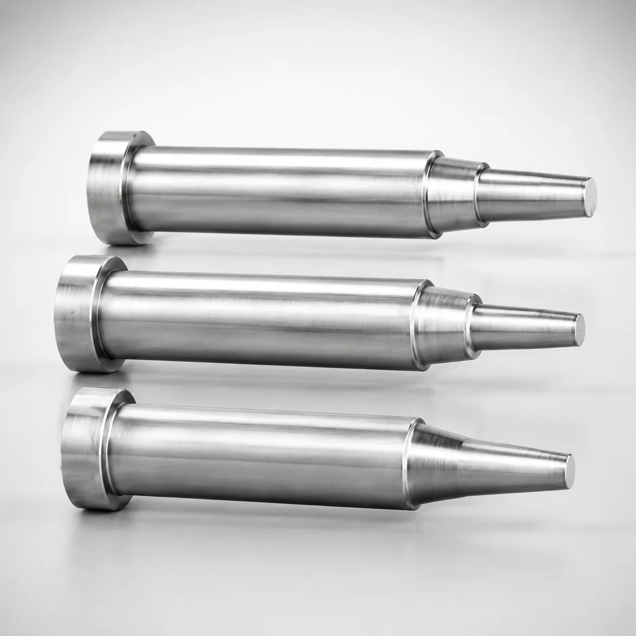
Two-Step Core Pins Head T=4 mm
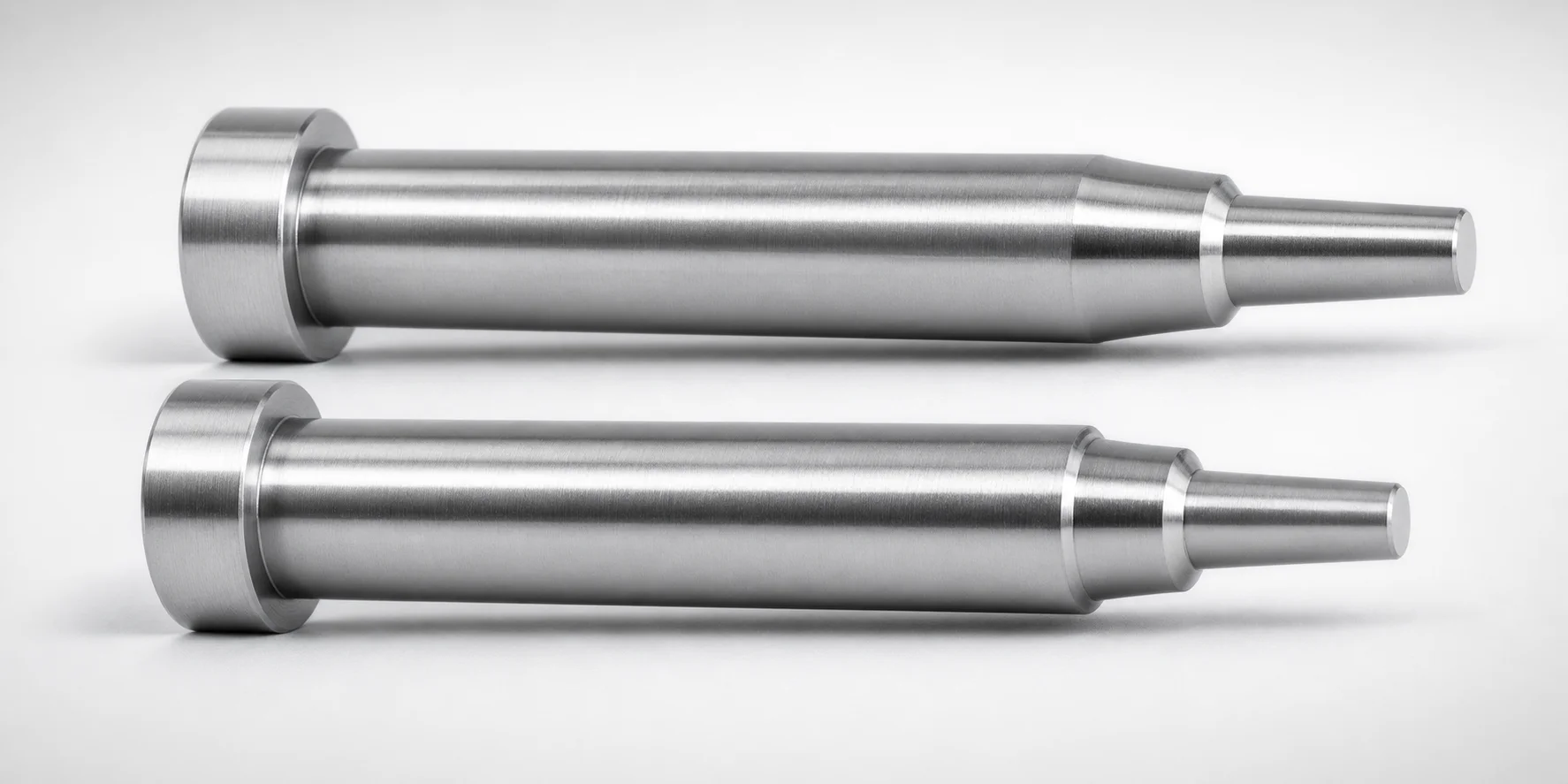
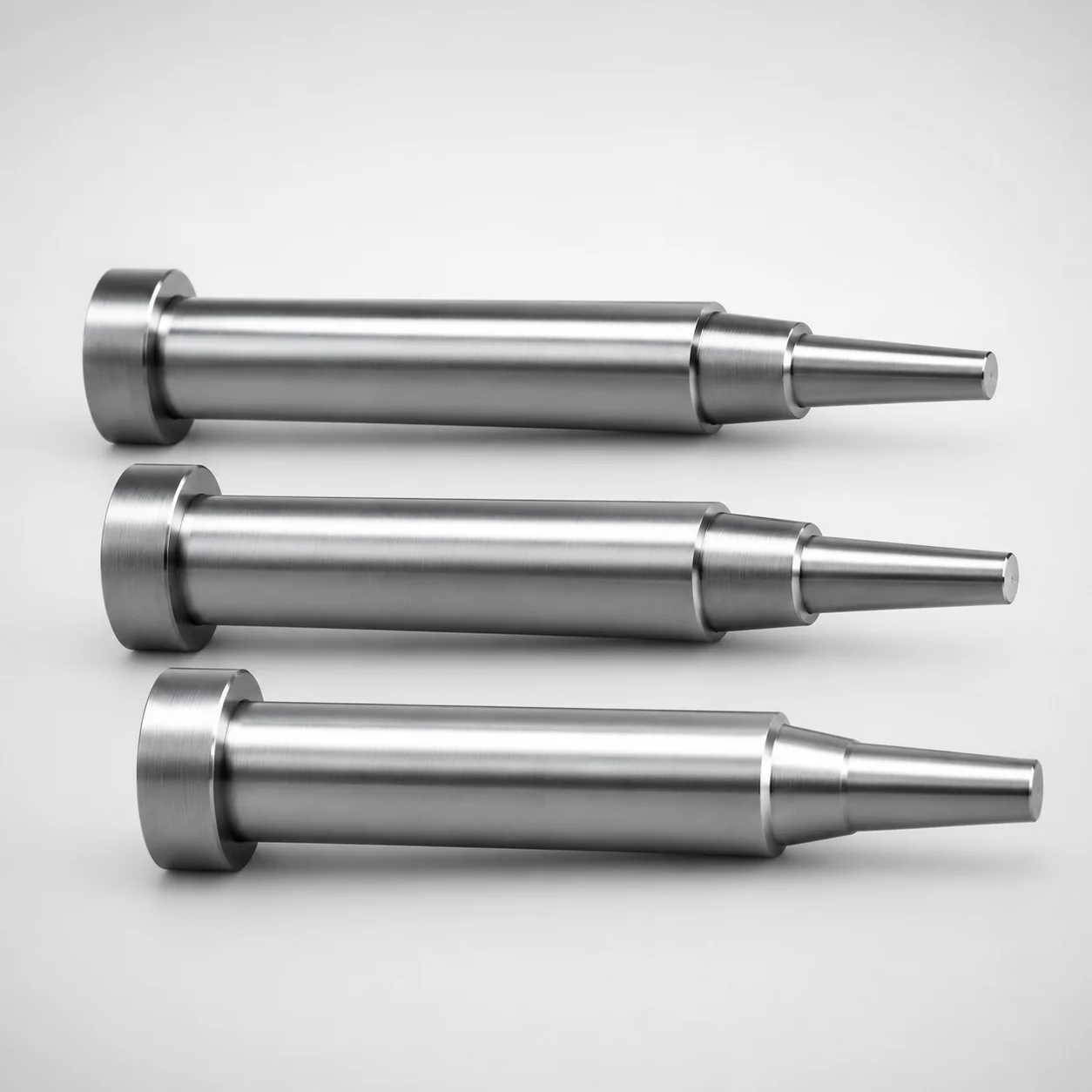
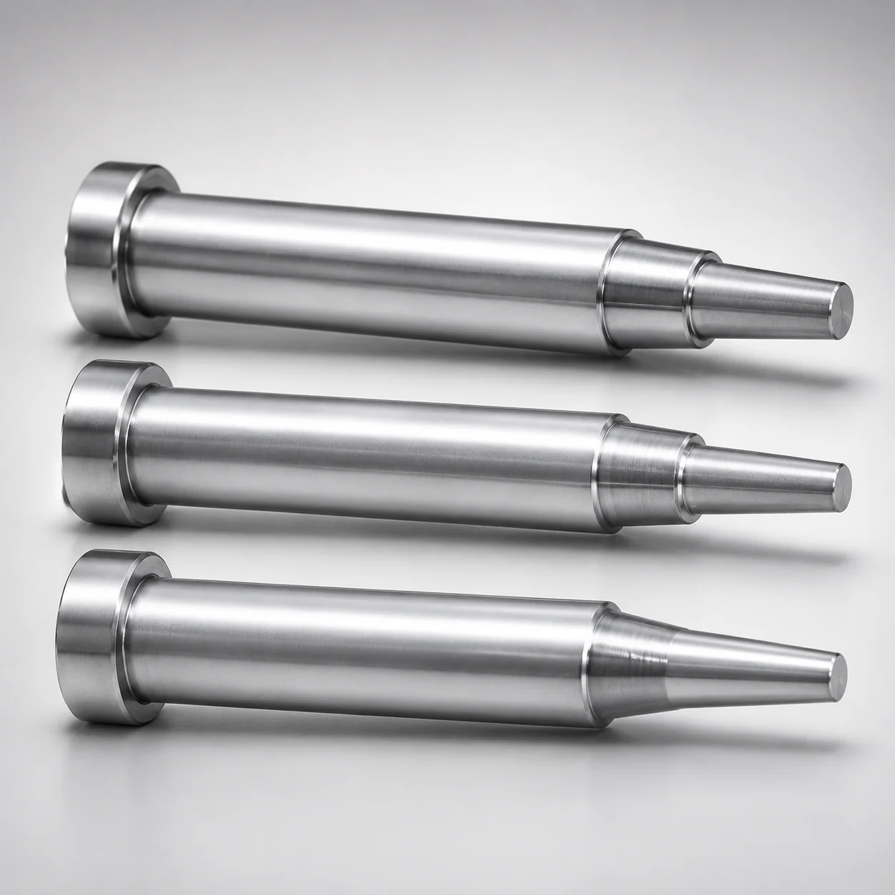
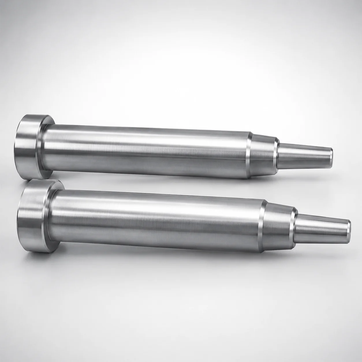
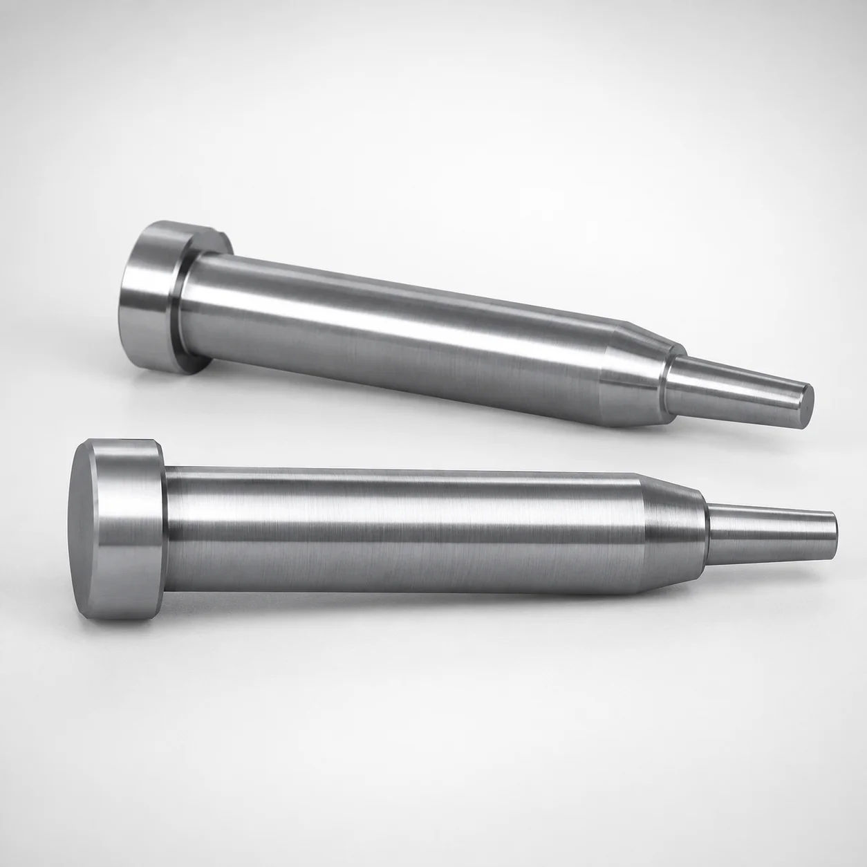
Two-Step Core Pins (Head T=4 mm) provide a stepped bearing surface for reliable positioning in precision molds, using tight shaft and length tolerances to support consistent ejection performance. The configurable shaft diameter allows easier matching to your core layout.
- Two-step geometry (two-stage diameters) improves core guidance stability during molding cycles
- Available in SKH51/SKD61/NAK80/DH2F/MAS1C hardened steel options for wear resistance
- Precision control supports L dimension (+0.02/0) for accurate core-to-block fit
- Commonly used as core locating and alignment pins in die and mold assemblies
Specifications
1908 configurations available
| Material | D/P (Shaft Diameter) (mm) | First Step Shape | Second Step Shape | No. (Nominal diameter) (mm) | A (Type of the first step diameter) (mm) | C (First step shape taper width) (mm) | E (Tip diameter) (mm) | F (Bearing bore length) (mm) | G (C chamfering width of the second step shape) (mm) | J (Type of the second step) (mm) | L (L dimension) (mm) | Q (Second step shape R chamfering) (mm) | R (First step type R) (mm) | V (Type of the second step) (mm) | Dimension Y (mm) | type |
|---|---|---|---|---|---|---|---|---|---|---|---|---|---|---|---|---|
| MAS1C | 1 ~ 1.49 | CA | A | 1.5 | - | - | 0.5 ~ 1.48 | 10 ~ 99 | - | - | 12 ~ 100 | - | - | 0.51 ~ 1.48 | 10.5 ~ 99.5 | - |
| MAS1C | 1.5 ~ 1.99 | CA | A | 2 | - | - | 0.7 ~ 1.97 | 10 ~ 99 | - | - | 12 ~ 100 | - | - | 0.7 ~ 1.98 | 10 ~ 99 | - |
| MAS1C | 2 ~ 2.49 | CA | A | 2.5 | - | - | 0.7 ~ 2.47 | 10 ~ 99 | - | - | 12 ~ 100 | - | - | 0.7 ~ 2.48 | 10 ~ 99 | - |
| MAS1C | 1 ~ 1.49 | CA | B | 1.5 | - | - | 0.5 ~ 1.48 | 10 ~ 98.8 | - | 0.5 ~ 1.48 | 12 ~ 100 | - | - | 0.51 ~ 1.48 | 10.5 ~ 99.3 | - |
| MAS1C | 1.5 ~ 1.99 | CA | B | 2 | - | - | 0.7 ~ 1.97 | 10 ~ 98 | - | 0.7 ~ 1.97 | 12 ~ 100 | - | - | 0.71 ~ 1.98 | 10 ~ 98 | - |
| MAS1C | 2 ~ 2.49 | CA | B | 2.5 | - | - | 0.7 ~ 2.47 | 10 ~ 98 | - | 0.7 ~ 2.47 | 12 ~ 100 | - | - | 0.71 ~ 2.48 | 10 ~ 98 | - |
| MAS1C | 1 ~ 1.49 | CA | C | 1.5 | - | - | 0.5 ~ 1.48 | 10 ~ 99 | - | 0.5 ~ 1.48 | 12 ~ 100 | - | - | 0.51 ~ 1.48 | 10.5 ~ 99.5 | - |
| MAS1C | 1.5 ~ 1.99 | CA | C | 2 | - | - | 0.7 ~ 1.97 | 10 ~ 99.5 | - | 0.7 ~ 1.97 | 12 ~ 100 | - | - | 0.71 ~ 1.98 | 10 ~ 99.5 | - |
| MAS1C | 2 ~ 2.49 | CA | C | 2.5 | - | - | 0.7 ~ 2.47 | 10 ~ 99.5 | - | 0.7 ~ 2.47 | 12 ~ 100 | - | - | 0.7 ~ 2.47 | 10 ~ 99.5 | - |
| MAS1C | 1 ~ 1.49 | CA | D | 1.5 | - | - | 0.5 ~ 1.48 | 10 ~ 98.9 | 0.1 ~ 0.5 | 0.5 ~ 1.48 | 12 ~ 100 | - | - | 0.51 ~ 1.48 | 10.5 ~ 99.4 | - |
| MAS1C | 1.5 ~ 1.99 | CA | D | 2 | - | - | 0.7 ~ 1.97 | 10 ~ 99.5 | 0.1 ~ 0.5 | 0.7 ~ 1.97 | 12 ~ 100 | - | - | 0.71 ~ 1.98 | 10 ~ 99.5 | - |
| MAS1C | 2 ~ 2.49 | CA | D | 2.5 | - | - | 0.7 ~ 2.47 | 10 ~ 99.5 | 0.1 ~ 0.5 | 0.7 ~ 2.47 | 12 ~ 100 | - | - | 0.71 ~ 2.48 | 10 ~ 99.5 | - |
| MAS1C | 1 ~ 1.49 | CA | E | 1.5 | - | - | 0.5 ~ 1.48 | 10 ~ 98.7 | - | 0.5 ~ 1.48 | 12 ~ 100 | 0.2 ~ 0.4 | - | 0.51 ~ 1.48 | 10.5 ~ 99.2 | - |
| MAS1C | 1.5 ~ 1.99 | CA | E | 2 | - | - | 0.7 ~ 1.97 | 10 ~ 99.5 | - | 0.7 ~ 1.97 | 12 ~ 100 | 0.2 ~ 0.6 | - | 0.71 ~ 1.98 | 10 ~ 99.5 | - |
| MAS1C | 2 ~ 2.49 | CA | E | 2.5 | - | - | 0.7 ~ 2.47 | 10 ~ 99.5 | - | 0.7 ~ 2.47 | 12 ~ 100 | 0.2 ~ 0.8 | - | 0.71 ~ 2.48 | 10 ~ 99.5 | - |
| SKD61 | 1 ~ 1.49 | CA | A | 1.5 | - | - | 0.5 ~ 1.48 | 10 ~ 99 | - | - | 12 ~ 100 | - | - | 0.51 ~ 1.48 | 10.5 ~ 99.5 | - |
| SKD61 | 1.5 ~ 1.99 | CA | A | 2 | - | - | 0.7 ~ 1.97 | 10 ~ 99.7 | - | - | 12 ~ 100 | - | - | 0.7 ~ 1.98 | 10 ~ 99.5 | - |
| SKD61 | 2 ~ 2.49 | CA | A | 2.5 | - | - | 0.7 ~ 2.47 | 10 ~ 99.7 | - | - | 12 ~ 100 | - | - | 0.7 ~ 2.48 | 10 ~ 99.5 | - |
| SKD61 | 2.5 ~ 2.99 | CA | A | 3 | - | - | 1 ~ 2.97 | 10 ~ 99.7 | - | - | 12 ~ 100 | - | - | 1 ~ 2.98 | 10 ~ 99.5 | - |
| SKD61 | 3 ~ 3.49 | CA | A | 3.5 | - | - | 1 ~ 3.47 | 10 ~ 99.7 | - | - | 12 ~ 100 | - | - | 1 ~ 3.48 | 10 ~ 99.5 | - |
| SKD61 | 3.5 ~ 3.99 | CA | A | 4 | - | - | 1 ~ 3.97 | 10 ~ 119.7 | - | - | 12 ~ 120 | - | - | 1 ~ 3.98 | 10 ~ 119.5 | - |
| SKD61 | 4 ~ 4.49 | CA | A | 4.5 | - | - | 1.5 ~ 4.47 | 10 ~ 119.7 | - | - | 12 ~ 120 | - | - | 1.5 ~ 4.48 | 10 ~ 119.5 | - |
| SKD61 | 4.5 ~ 4.99 | CA | A | 5 | - | - | 1.5 ~ 4.97 | 10 ~ 119.7 | - | - | 12 ~ 150 | - | - | 1.5 ~ 4.98 | 10 ~ 119.5 | - |
| SKD61 | 5 ~ 5.49 | CA | A | 5.5 | - | - | 1.5 ~ 5.47 | 10 ~ 119.7 | - | - | 12 ~ 150 | - | - | 1.5 ~ 5.48 | 10 ~ 119.5 | - |
| SKD61 | 5.5 ~ 5.99 | CA | A | 6 | - | - | 2 ~ 5.97 | 10 ~ 119.7 | - | - | 12 ~ 150 | - | - | 2 ~ 5.98 | 10 ~ 119.5 | - |
| SKD61 | 6 ~ 6.49 | CA | A | 6.5 | - | - | 2 ~ 6.47 | 10 ~ 119.7 | - | - | 12 ~ 150 | - | - | 2 ~ 6.48 | 10 ~ 119.5 | - |
| SKD61 | 6.5 ~ 6.99 | CA | A | 7 | - | - | 2 ~ 6.97 | 10 ~ 119.7 | - | - | 12 ~ 150 | - | - | 2 ~ 6.98 | 10 ~ 119.5 | - |
| SKD61 | 7 ~ 7.99 | CA | A | 8 | - | - | 2 ~ 7.97 | 10 ~ 119.7 | - | - | 12 ~ 150 | - | - | 2 ~ 7.98 | 10 ~ 119.5 | - |
| SKD61 | 8 ~ 9.99 | CA | A | 10 | - | - | 2 ~ 9.97 | 10 ~ 119.7 | - | - | 12 ~ 150 | - | - | 2 ~ 9.98 | 10 ~ 119.5 | - |
| SKD61 | 10 ~ 12.99 | CA | A | 13 | - | - | 2.5 ~ 12.97 | 10 ~ 119.7 | - | - | 12 ~ 150 | - | - | 2.5 ~ 12.98 | 10 ~ 119.5 | - |
| SKD61 | 13 ~ 15.99 | CA | A | 16 | - | - | 2.5 ~ 15.97 | 10 ~ 119.7 | - | - | 12 ~ 150 | - | - | 2.5 ~ 15.98 | 10 ~ 119.5 | - |
| SKD61 | 16 ~ 19.99 | CA | A | 20 | - | - | 5 ~ 15.97 | 28 ~ 119.7 | - | - | 30 ~ 150 | - | - | 5 ~ 15.98 | 28 ~ 119.5 | - |
| SKD61 | 1 ~ 1.49 | CA | B | 1.5 | - | - | 0.5 ~ 1.48 | 10 ~ 98.8 | - | 0.5 ~ 1.48 | 12 ~ 100 | - | - | 0.51 ~ 1.48 | 10.5 ~ 99.3 | - |
| SKD61 | 1.5 ~ 1.99 | CA | B | 2 | - | - | 0.7 ~ 1.97 | 10 ~ 99.7 | - | 0.7 ~ 1.97 | 12 ~ 100 | - | - | 0.7 ~ 1.98 | 10 ~ 99.5 | - |
| SKD61 | 2 ~ 2.49 | CA | B | 2.5 | - | - | 0.7 ~ 2.47 | 10 ~ 99.7 | - | 0.7 ~ 2.47 | 12 ~ 100 | - | - | 0.7 ~ 2.48 | 10 ~ 99.5 | - |
| SKD61 | 2.5 ~ 2.99 | CA | B | 3 | - | - | 1 ~ 2.97 | 10 ~ 99.7 | - | 1 ~ 2.97 | 12 ~ 100 | - | - | 1 ~ 2.98 | 10 ~ 99.5 | - |
| SKD61 | 3 ~ 3.49 | CA | B | 3.5 | - | - | 1 ~ 3.47 | 10 ~ 99.7 | - | 1 ~ 3.47 | 12 ~ 100 | - | - | 1 ~ 3.48 | 10 ~ 99.5 | - |
| SKD61 | 3.5 ~ 3.99 | CA | B | 4 | - | - | 1 ~ 3.97 | 10 ~ 119.7 | - | 1 ~ 3.97 | 12 ~ 120 | - | - | 1 ~ 3.98 | 10 ~ 119.5 | - |
| SKD61 | 4 ~ 4.49 | CA | B | 4.5 | - | - | 1.5 ~ 4.47 | 10 ~ 119.7 | - | 1.5 ~ 4.47 | 12 ~ 120 | - | - | 1.5 ~ 4.48 | 10 ~ 119.5 | - |
| SKD61 | 4.5 ~ 4.99 | CA | B | 5 | - | - | 1.5 ~ 4.97 | 10 ~ 119.7 | - | 1.5 ~ 4.97 | 12 ~ 150 | - | - | 1.5 ~ 4.98 | 10 ~ 119.5 | - |
| SKD61 | 5 ~ 5.49 | CA | B | 5.5 | - | - | 1.5 ~ 5.47 | 10 ~ 119.7 | - | 1.5 ~ 5.47 | 12 ~ 150 | - | - | 1.5 ~ 5.48 | 10 ~ 119.5 | - |
| SKD61 | 5.5 ~ 5.99 | CA | B | 6 | - | - | 2 ~ 5.97 | 10 ~ 119.7 | - | 2 ~ 5.97 | 12 ~ 150 | - | - | 2 ~ 5.98 | 10 ~ 119.5 | - |
| SKD61 | 6 ~ 6.49 | CA | B | 6.5 | - | - | 2 ~ 6.47 | 10 ~ 119.7 | - | 2 ~ 6.47 | 12 ~ 150 | - | - | 2 ~ 6.48 | 10 ~ 119.5 | - |
| SKD61 | 6.5 ~ 6.99 | CA | B | 7 | - | - | 2 ~ 6.97 | 10 ~ 119.7 | - | 2 ~ 6.97 | 12 ~ 150 | - | - | 2 ~ 6.98 | 10 ~ 119.5 | - |
| SKD61 | 7 ~ 7.99 | CA | B | 8 | - | - | 2 ~ 7.97 | 10 ~ 119.7 | - | 2 ~ 7.97 | 12 ~ 150 | - | - | 2 ~ 7.98 | 10 ~ 119.5 | - |
| SKD61 | 8 ~ 9.99 | CA | B | 10 | - | - | 2 ~ 9.97 | 10 ~ 119.7 | - | 2 ~ 9.97 | 12 ~ 150 | - | - | 2 ~ 9.98 | 10 ~ 119.5 | - |
| SKD61 | 10 ~ 12.99 | CA | B | 13 | - | - | 2.5 ~ 12.97 | 10 ~ 119.7 | - | 2.5 ~ 12.97 | 12 ~ 150 | - | - | 2.5 ~ 12.98 | 10 ~ 119.5 | - |
| SKD61 | 13 ~ 15.99 | CA | B | 16 | - | - | 2.5 ~ 15.97 | 10 ~ 119.7 | - | 2.5 ~ 15.97 | 12 ~ 150 | - | - | 2.5 ~ 15.98 | 10 ~ 119.5 | - |
| SKD61 | 16 ~ 19.99 | CA | B | 20 | - | - | 5 ~ 19.97 | 28 ~ 119.7 | - | 5 ~ 19.97 | 30 ~ 150 | - | - | 5 ~ 19.98 | 28 ~ 119.5 | - |
| SKD61 | 1 ~ 1.49 | CA | C | 1.5 | - | - | 0.5 ~ 1.48 | 10 ~ 99 | - | 0.5 ~ 1.48 | 12 ~ 100 | - | - | 0.51 ~ 1.48 | 10.5 ~ 99.5 | - |
Product Guide
Application Scenarios+
Two-step core pins are used in injection mold tooling where repeatable alignment between the core and mold base is critical. This variant’s stepped bearing head (T=4 mm) creates a stable guidance surface, helping maintain consistent positioning through repeated press cycles.
- Automotive connector and sensor molds: The configurable shaft diameter (D/P = 1 to 16 mm) lets designers match the pin to the core-block layout, improving core-to-cavity alignment and supporting reliable ejection repeatability.
- Medical device housing molds: Tight dimensional control using the specified L dimension (+0.02/0) supports accurate assembly fit, which is important when molded parts require stable geometry over high mold counts.
- General die and mold assemblies: The two-stage diameters provide improved core guidance stability, reducing the risk of misalignment during opening/closing.
Hardened steel options further suit environments with frequent contact and cyclic loading.
Material & Process Details+
The core pin is offered in multiple hardened steels selected for wear resistance and dimensional stability under repeated mold cycles. Available materials include SKH51, SKD61, NAK80, DH2F, and MAS1C (exact grades and procurement state depend on the chosen SKU).
- SKH51: High-hardness tool steel commonly selected for abrasion resistance where sliding/bearing wear is significant.
- SKD61: Heat-check and toughness balanced for hot-work tooling applications.
- NAK80: Often chosen where surface stability and machining/finishing balance is required.
- DH2F / MAS1C: Variants typically selected for wear resistance and mold service life based on cavity/core contact conditions.
For each option, pins are manufactured from hardened steel stock and finished to control bearing surfaces. Hardness (HRC) and heat-treatment specifics are tied to the selected material variant; select the grade that best matches your expected wear vs. toughness trade-off.
Sizing & Selection Guide+
Select dimensions by matching the pin’s stepped geometry to your core guidance and locating scheme. Start with D/P (shaft diameter) = 1 to 16 mm to ensure the pin fits the corresponding core-block hole. Then choose the required F (bearing bore length) = 10 to 98 mm (bearing contact length) to match the depth of your guidance feature.
- Choose the first-step style (CA, CB, CC, CD, CE) and first-step diameter type A = 0.5 to 5.1 mm, ensuring the upper step provides the intended alignment/bearing surface.
- Select the second-step shape (A, B, C, D, E) and related dimensions such as G (0.1 to 0.5 mm), J (0.5 to 5 mm), and V (0.5 to 5.1 mm) to match your stepped pocket profile.
- Verify the overall L dimension = 12 to 100 mm (or other listed ranges) for correct stack-up; when applicable, use the provided L tolerance (+0.02/0) for fit.
- Confirm G/Q/R chamfering/fillet features (e.g., Q = 0.2, R = 0.1 to 0.2 mm) to avoid interference at the pocket edges.
The shaft diameter is configurable, while geometry sets (step shapes) are fixed per selection.
Frequently Asked Questions
How do I choose the right configurable shaft diameter (D/P) for a two-step core pin?+
Match D/P to the diameter of the mating core-block hole or bushing bore. This product supports D/P = 1 to 16 mm, so select the closest functional diameter that prevents excessive clearance while avoiding interference. If you are designing for repeatable alignment, confirm the stack-up against the stepped bearing surfaces and the required L length range.
What L dimension range should I use to ensure correct core-to-block fit?+
Choose L from the available options listed for the series (e.g., 12 to 100 mm, 12 to 120 mm, 12 to 150 mm, 30 to 150 mm, or 30 to 120 mm). When using the specified tolerance guidance, apply L dimension (+0.02/0) during assembly fit calculations. This helps ensure the locating height stays within the designed tolerance window.
How do the first-step and second-step shapes affect core guidance stability?+
The pin uses a stepped bearing concept with two diameters to improve guidance stability during opening/closing. Select the first-step shape (CA, CB, CC, CD, CE) and second-step shape (A, B, C, D, E) to match your corresponding stepped pocket geometry. Also verify related features such as G (0.1 to 0.5 mm) and fillet/chamfer dimensions (Q and R) to prevent edge interference that could reduce repeatability.
Which material should I select for wear resistance versus toughness in core pin applications?+
Material choice is driven by the wear-to-toughness requirement in your mold service. Options include SKH51, SKD61, NAK80, DH2F, and MAS1C, each suited to different tool performance priorities. If abrasive/bearing wear dominates, consider the higher-hardness wear-focused grades; if cyclic toughness and hot-work service balance is more critical, SKD61-type applications are commonly selected.
What is the bearing bore length (F) and how does it relate to the guidance contact area?+
F is the bearing bore length and ranges from 10 to 98 mm for this series. Use F to align the bearing contact zone with your core-block guidance feature depth, ensuring stable positioning without over-engagement. Re-check that the chosen stepped shapes and overall Y (10 to 98.5 mm) are consistent with your pocket/locator layout.
Related Products
Need Custom Specifications?
Our engineering team can help with custom configurations, material selection, and volume pricing.