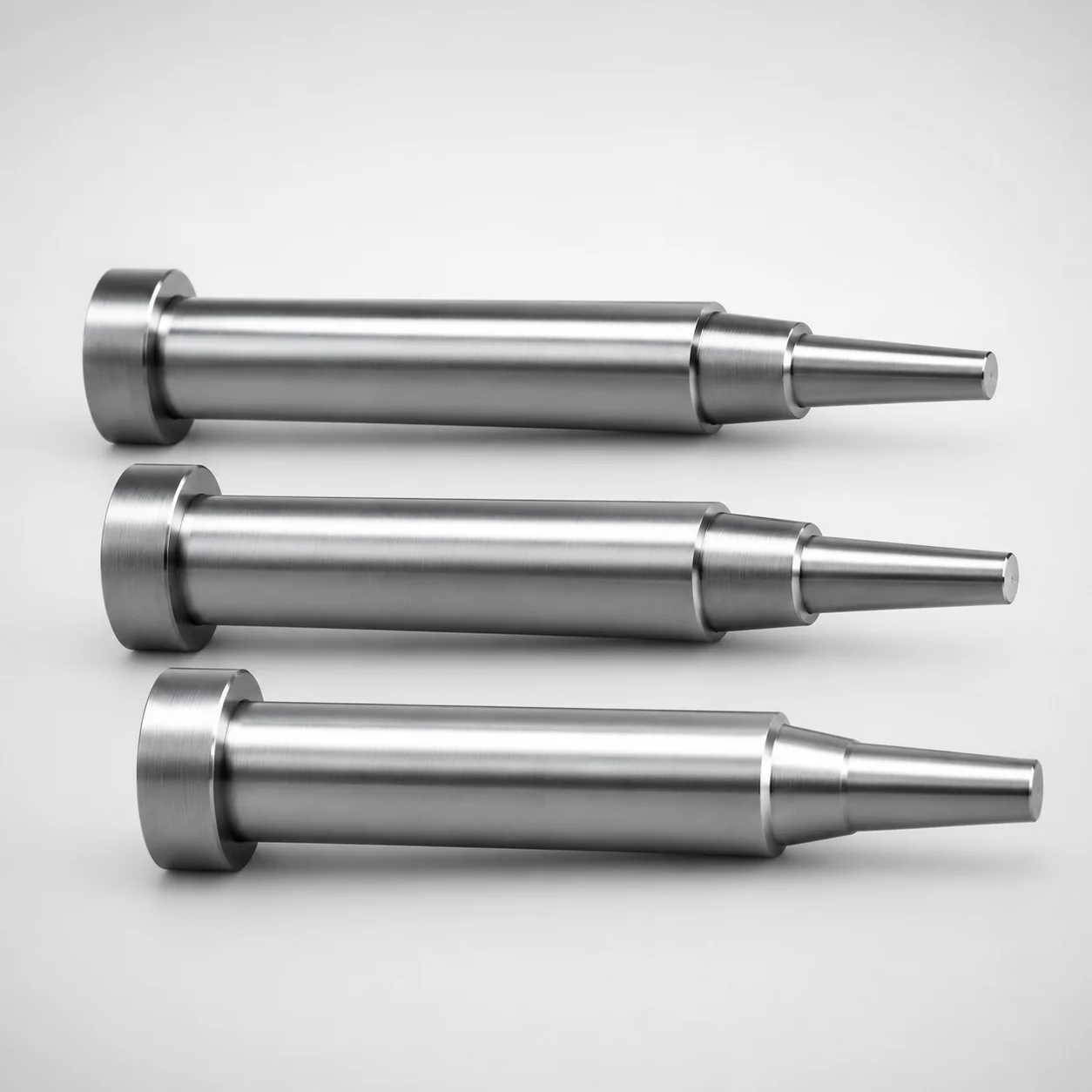
Precision Two-Step Core Pins - M2/H13 Steel, Head T=4 mm
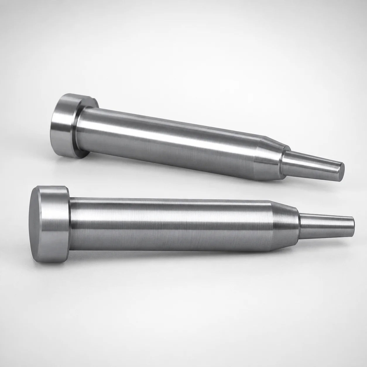
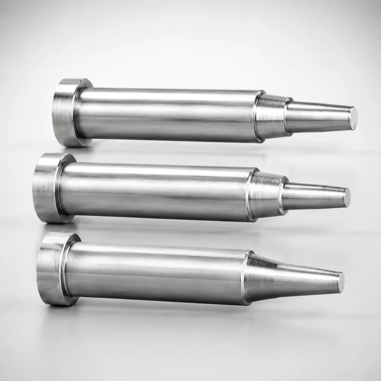
Precision Two-Step Core Pins (M2/H13 steel) with Head T=4 mm are engineered for accurate two-stage locating in injection and die tooling. The stepped geometry and fine tolerances help maintain consistent alignment during mold operation.
- Two-step core pin two-step design supports reliable positioning at both stages
- Constructed from M2/H13 steel for durable wear resistance in demanding mold cycles
- Tight L dimension tolerance (+0.01/0) and controlled tip geometry for improved fit repeatability
- Configured for precision core assemblies where shaft and location accuracy are critical
Specifications
1873 configurations available
| Material | D/P (Shaft Diameter) (mm) | First Step Shape | Second Step Shape | No. (Nominal diameter) (mm) | A (Type of the first step diameter) (mm) | C (First step shape taper width) (mm) | E (Tip diameter) (mm) | F (Bearing bore length) (mm) | FC (Makes F dimension shorter than F min) (mm) | G (C chamfering width of the second step shape) (mm) | J (Type of the second step) (mm) | L (L dimension) (mm) | Q (Second step shape R chamfering) (mm) | R (First step type R) (mm) | V (Type of the second step) (mm) | Dimension Y (mm) | type |
|---|---|---|---|---|---|---|---|---|---|---|---|---|---|---|---|---|---|
| SKH51 | 1 ~ 1.49 | CA | A | 1.5 | - | - | 0.5 ~ 1.48 | 12 ~ 98.7 | - | - | - | 7 ~ 100 | - | - | 0.5 ~ 1.49 | 5.5 ~ 99.6 | - |
| SKH51 | 1 ~ 1.49 | CA | A | 1.5 | - | - | 0.5 ~ 1.48 | - | 5 ~ 13.99 | - | - | 7 ~ 100 | - | - | 0.5 ~ 1.49 | 5.5 ~ 99.6 | - |
| SKH51 | 1.5 ~ 1.99 | CA | A | 2 | - | - | 0.7 ~ 1.97 | 12 ~ 98.7 | - | - | - | 7 ~ 100 | - | - | 0.7 ~ 1.98 | 5.5 ~ 99.6 | - |
| SKH51 | 1.5 ~ 1.99 | CA | A | 2 | - | - | 0.7 ~ 1.97 | - | 5 ~ 13.99 | - | - | 7 ~ 100 | - | - | 0.7 ~ 1.98 | 5.5 ~ 99.6 | - |
| SKH51 | 2 ~ 2.49 | CA | A | 2.5 | - | - | 0.7 ~ 2.47 | 12 ~ 98.7 | - | - | - | 7 ~ 100 | - | - | 0.7 ~ 2.48 | 5.5 ~ 99.6 | - |
| SKH51 | 2 ~ 2.49 | CA | A | 2.5 | - | - | 0.7 ~ 2.47 | - | 5 ~ 13.99 | - | - | 7 ~ 100 | - | - | 0.7 ~ 2.48 | 5.5 ~ 99.6 | - |
| SKH51 | 2.5 ~ 2.99 | CA | A | 3 | - | - | 1 ~ 2.97 | 12 ~ 98.7 | - | - | - | 7 ~ 100 | - | - | 1 ~ 2.98 | 5.5 ~ 99.6 | - |
| SKH51 | 2.5 ~ 2.99 | CA | A | 3 | - | - | 1 ~ 2.97 | - | 5 ~ 13.99 | - | - | 7 ~ 100 | - | - | 1 ~ 2.98 | 5.5 ~ 99.6 | - |
| SKH51 | 3 ~ 3.49 | CA | A | 3.5 | - | - | 1 ~ 3.47 | 12 ~ 98.7 | - | - | - | 7 ~ 100 | - | - | 1 ~ 3.48 | 5.5 ~ 99.6 | - |
| SKH51 | 3 ~ 3.49 | CA | A | 3.5 | - | - | 1 ~ 3.47 | - | 5 ~ 13.99 | - | - | 7 ~ 100 | - | - | 1 ~ 3.48 | 5.5 ~ 99.6 | - |
| SKH51 | 3.5 ~ 3.99 | CA | A | 4 | - | - | 1 ~ 3.97 | 12 ~ 119.7 | - | - | - | 7 ~ 120 | - | - | 1 ~ 3.98 | 5.5 ~ 119.6 | - |
| SKH51 | 3.5 ~ 3.99 | CA | A | 4 | - | - | 1 ~ 3.97 | - | 5 ~ 13.99 | - | - | 7 ~ 120 | - | - | 1 ~ 3.98 | 5.5 ~ 119.6 | - |
| SKH51 | 4 ~ 4.49 | CA | A | 4.5 | - | - | 1.5 ~ 4.47 | 12 ~ 119.7 | - | - | - | 7 ~ 120 | - | - | 1.5 ~ 4.48 | 5.5 ~ 119.6 | - |
| SKH51 | 4 ~ 4.49 | CA | A | 4.5 | - | - | 1.5 ~ 4.47 | - | 5 ~ 13.99 | - | - | 7 ~ 120 | - | - | 1.5 ~ 4.48 | 5.5 ~ 119.6 | - |
| SKH51 | 4.5 ~ 4.99 | CA | A | 5 | - | - | 1.5 ~ 4.97 | 12 ~ 149.5 | - | - | - | 7 ~ 150 | - | - | 1.5 ~ 4.98 | 5.5 ~ 149.6 | - |
| SKH51 | 4.5 ~ 4.99 | CA | A | 5 | - | - | 1.5 ~ 4.97 | - | 5 ~ 13.99 | - | - | 7 ~ 150 | - | - | 1.5 ~ 4.98 | 5.5 ~ 149.6 | - |
| SKH51 | 5 ~ 5.49 | CA | A | 5.5 | - | - | 1.5 ~ 5.47 | 12 ~ 149.5 | - | - | - | 7 ~ 150 | - | - | 1.5 ~ 5.48 | 5.5 ~ 149.6 | - |
| SKH51 | 5 ~ 5.49 | CA | A | 5.5 | - | - | 1.5 ~ 5.47 | - | 5 ~ 13.99 | - | - | 7 ~ 150 | - | - | 1.5 ~ 5.48 | 5.5 ~ 149.6 | - |
| SKH51 | 5.5 ~ 5.99 | CA | A | 6 | - | - | 2 ~ 5.97 | 12 ~ 149.5 | - | - | - | 7 ~ 150 | - | - | 2 ~ 5.98 | 5.5 ~ 149.6 | - |
| SKH51 | 5.5 ~ 5.99 | CA | A | 6 | - | - | 2 ~ 5.97 | - | 5 ~ 13.99 | - | - | 7 ~ 150 | - | - | 2 ~ 5.98 | 5.5 ~ 149.6 | - |
| SKH51 | 6 ~ 6.49 | CA | A | 6.5 | - | - | 2 ~ 6.47 | 12 ~ 149.5 | - | - | - | 7 ~ 150 | - | - | 2 ~ 6.48 | 5.5 ~ 149.6 | - |
| SKH51 | 6 ~ 6.49 | CA | A | 6.5 | - | - | 2 ~ 6.47 | - | 5 ~ 13.99 | - | - | 7 ~ 150 | - | - | 2 ~ 6.48 | 5.5 ~ 149.6 | - |
| SKH51 | 6.5 ~ 6.99 | CA | A | 7 | - | - | 2 ~ 6.97 | 12 ~ 149.5 | - | - | - | 7 ~ 150 | - | - | 2 ~ 6.98 | 5.5 ~ 149.6 | - |
| SKH51 | 6.5 ~ 6.99 | CA | A | 7 | - | - | 2 ~ 6.97 | - | 5 ~ 13.99 | - | - | 7 ~ 150 | - | - | 2 ~ 6.98 | 5.5 ~ 149.6 | - |
| SKH51 | 7 ~ 7.995 | CA | A | 8 | - | - | 2 ~ 7.97 | 12 ~ 149.5 | - | - | - | 7 ~ 150 | - | - | 2 ~ 7.98 | 5.5 ~ 149.6 | - |
| SKH51 | 7 ~ 7.995 | CA | A | 8 | - | - | 2 ~ 7.97 | - | 5 ~ 13.99 | - | - | 7 ~ 150 | - | - | 2 ~ 7.98 | 5.5 ~ 149.6 | - |
| SKH51 | 8 ~ 9.99 | CA | A | 10 | - | - | 2 ~ 9.97 | 12 ~ 149.5 | - | - | - | 7 ~ 150 | - | - | 2 ~ 9.98 | 5.5 ~ 149.6 | - |
| SKH51 | 8 ~ 9.99 | CA | A | 10 | - | - | 2 ~ 9.97 | - | 5 ~ 13.99 | - | - | 7 ~ 150 | - | - | 2 ~ 9.98 | 5.5 ~ 149.6 | - |
| SKH51 | 10 ~ 12.99 | CA | A | 13 | - | - | 2.5 ~ 12.97 | 12 ~ 149.5 | - | - | - | 7 ~ 150 | - | - | 2.5 ~ 12.98 | 5.5 ~ 149.6 | - |
| SKH51 | 10 ~ 12.99 | CA | A | 13 | - | - | 2.5 ~ 12.97 | - | 5 ~ 13.99 | - | - | 7 ~ 150 | - | - | 2.5 ~ 12.98 | 5.5 ~ 149.6 | - |
| SKH51 | 13 ~ 15.99 | CA | A | 16 | - | - | 2.5 ~ 15.97 | 12 ~ 149.5 | - | - | - | 7 ~ 150 | - | - | 2.5 ~ 15.98 | 5.5 ~ 149.6 | - |
| SKH51 | 13 ~ 15.99 | CA | A | 16 | - | - | 2.5 ~ 15.97 | - | 5 ~ 13.99 | - | - | 7 ~ 150 | - | - | 2.5 ~ 15.98 | 5.5 ~ 149.6 | - |
| SKH51 | 16 ~ 19.99 | CA | A | 20 | - | - | 5 ~ 15.97 | 28 ~ 149.5 | - | - | - | 6.5 ~ 13.99 | - | - | 5 ~ 15.98 | 6.5 ~ 149.6 | - |
| SKH51 | 16 ~ 19.99 | CA | A | 20 | - | - | 5 ~ 15.97 | - | 5 ~ 29.99 | - | - | 6.5 ~ 13.99 | - | - | 5 ~ 15.98 | 6.5 ~ 149.6 | - |
| SKH51 | 16 ~ 19.99 | CA | A | 20 | - | - | 5 ~ 15.97 | 28 ~ 149.5 | - | - | - | 30 ~ 150 | - | - | 5 ~ 15.98 | 6.5 ~ 149.6 | - |
| SKH51 | 16 ~ 19.99 | CA | A | 20 | - | - | 5 ~ 15.97 | - | 5 ~ 29.99 | - | - | 30 ~ 150 | - | - | 5 ~ 15.98 | 6.5 ~ 149.6 | - |
| SKH51 | 1 ~ 1.49 | CA | B | 1.5 | - | - | 0.5 ~ 1.48 | 12 ~ 98.7 | - | - | 0.5 ~ 1.48 | 7 ~ 100 | - | - | 0.51 ~ 1.49 | 5.5 ~ 99.6 | - |
| SKH51 | 1 ~ 1.49 | CA | B | 1.5 | - | - | 0.5 ~ 1.48 | - | 5 ~ 13.99 | - | 0.5 ~ 1.48 | 7 ~ 100 | - | - | 0.51 ~ 1.49 | 5.5 ~ 99.6 | - |
| SKH51 | 1.5 ~ 1.99 | CA | B | 2 | - | - | 0.7 ~ 1.97 | 12 ~ 98.7 | - | - | 0.7 ~ 1.97 | 7 ~ 100 | - | - | 0.71 ~ 1.98 | 5.5 ~ 99.6 | - |
| SKH51 | 1.5 ~ 1.99 | CA | B | 2 | - | - | 0.7 ~ 1.97 | - | 5 ~ 13.99 | - | 0.7 ~ 1.97 | 7 ~ 100 | - | - | 0.71 ~ 1.98 | 5.5 ~ 99.6 | - |
| SKH51 | 2 ~ 2.49 | CA | B | 2.5 | - | - | 0.7 ~ 2.47 | 12 ~ 98.7 | - | - | 0.7 ~ 2.47 | 7 ~ 100 | - | - | 0.71 ~ 2.48 | 5.5 ~ 99.6 | - |
| SKH51 | 2 ~ 2.49 | CA | B | 2.5 | - | - | 0.7 ~ 2.47 | - | 5 ~ 13.99 | - | 0.7 ~ 2.47 | 7 ~ 100 | - | - | 0.71 ~ 2.48 | 5.5 ~ 99.6 | - |
| SKH51 | 2.5 ~ 2.99 | CA | B | 3 | - | - | 1 ~ 2.97 | 12 ~ 98.7 | - | - | 1 ~ 2.97 | 7 ~ 100 | - | - | 1.01 ~ 2.98 | 5.5 ~ 99.6 | - |
| SKH51 | 2.5 ~ 2.99 | CA | B | 3 | - | - | 1 ~ 2.97 | - | 5 ~ 13.99 | - | 1 ~ 2.97 | 7 ~ 100 | - | - | 1.01 ~ 2.98 | 5.5 ~ 99.6 | - |
| SKH51 | 3 ~ 4.49 | CA | B | 3.5 | - | - | 1 ~ 3.47 | 12 ~ 98.7 | - | - | 1 ~ 3.47 | 7 ~ 100 | - | - | 1.01 ~ 3.48 | 5.5 ~ 99.6 | - |
| SKH51 | 3 ~ 4.49 | CA | B | 3.5 | - | - | 1 ~ 3.47 | - | 5 ~ 13.99 | - | 1 ~ 3.47 | 7 ~ 100 | - | - | 1.01 ~ 3.48 | 5.5 ~ 99.6 | - |
| SKH51 | 3.5 ~ 3.99 | CA | B | 4 | - | - | 1 ~ 3.97 | 12 ~ 119.7 | - | - | 1 ~ 3.97 | 7 ~ 120 | - | - | 1.01 ~ 3.98 | 5.5 ~ 119.6 | - |
| SKH51 | 3.5 ~ 3.99 | CA | B | 4 | - | - | 1 ~ 3.97 | - | 5 ~ 13.99 | - | 1 ~ 3.97 | 7 ~ 120 | - | - | 1.01 ~ 3.98 | 5.5 ~ 119.6 | - |
| SKH51 | 4 ~ 4.49 | CA | B | 4.5 | - | - | 1.5 ~ 4.47 | 12 ~ 119.7 | - | - | 1.5 ~ 4.47 | 7 ~ 120 | - | - | 1.51 ~ 4.48 | 5.5 ~ 119.6 | - |
| SKH51 | 4 ~ 4.49 | CA | B | 4.5 | - | - | 1.5 ~ 4.47 | - | 5 ~ 13.99 | - | 1.5 ~ 4.47 | 7 ~ 120 | - | - | 1.51 ~ 4.48 | 5.5 ~ 119.6 | - |
Product Guide
Application Scenarios+
Two-step core pins like this are used in injection and die tooling where the mold needs repeatable, staged location during opening and closing. The stepped profile supports a controlled engagement sequence so alignment is achieved at the first stage and then refined at the second stage, improving positional stability under cycle loads.
- Automotive connector and housing molds: Ideal for guiding pin/guide interfaces where small positional errors can cause misalignment of inserts or ribs. The fine L tolerance (+0.01/0) and tight shaft fit help maintain consistent ejection and parting behavior.
- Medical device housings: Suitable for precision core assemblies that require stable alignment to preserve critical wall thickness and surface transitions. The wear-capable steel selection helps maintain location accuracy over many mold cycles.
- Consumer electronics shells: Useful in multi-cavity tools that see frequent opening/closing. The two-step geometry reduces the risk of drift by ensuring full contact at both stages.
This variant is suited to these applications because it combines a two-step locating strategy with controlled shaft and length features for stable fit repeatability.
Material & Process Details+
This product is offered in M2/H13 steel options, mapped to common mold steel families listed as SKH51 and SKD61. SKH51 is typically used as a high-speed steel (often associated with AISI M2 class), providing high hardness for wear and abrasion resistance. SKD61 corresponds to AISI H13 class, valued for toughness and good hot-work performance in injection tooling.
- Hardness & wear vs. toughness trade-off: High-hardness grades (SKH51/M2-type) tend to excel in wear resistance; SKD61/H13-type commonly balances wear with improved toughness for shock-prone tooling.
- Heat treatment state: For core pins, these steels are generally quenched and tempered to achieve the target hardness before service; surface finishing or secondary processes (when specified by the builder) can further improve wear behavior.
For the best results, select the grade based on expected contact wear and the severity of mold pressure and thermal cycling.
Sizing & Selection Guide+
Select the two-step core pin based on the required shaft diameter (D/P = 1 ~ 16 mm), the overall L dimension (L = 6.5 ~ 30 mm), and the end geometry that mates with your core/cavity locating surfaces.
- Match the locating diameter: Choose D/P within 1 ~ 16 mm to fit the bearing/guide bore intended for staged engagement.
- Verify engagement depth: Ensure your target length requirement falls within L = 6.5 ~ 30 mm, and confirm the bearing bore length compatibility using F (12 ~ 28 mm) where applicable for the supporting feature.
- Choose step shapes: Select the first step shape from CA~CE and the second step shape from A~E to align the staged contact area. Tip and intermediate dimensions must be consistent with A (0.5 ~ 5.01 mm) and E (0.5 ~ 5.01 mm).
- Tolerance & fit: This variant specifies a tight L dimension tolerance (+0.01/0), supporting stable ejection fit and repeatability. If your design is sensitive, prioritize the L callout and ensure clearance in the mating bore.
Use the available configuration parameters (step shapes, taper width, chamfers) to replicate your mold’s staged locating geometry while keeping D/P and L within the provided ranges.
Frequently Asked Questions
Which steel grade should I choose for a two-stage core pin—SKH51 (M2-type) or SKD61 (H13-type)?+
Use SKH51 when your priority is high wear resistance from frequent sliding contact at the pin interface. Use SKD61 when you need a better toughness balance for injection tooling that may see thermal cycling and mechanical shock.
Both are used for precision mold core components; the best choice depends on contact severity and how much toughness margin your mold design requires.
How do the two-step shapes (first step CA–CE and second step A–E) affect staged locating performance?+
The first step shape (CA, CB, CC, CD, CE) and the second step shape (A, B, C, D, E) define how the pin engages in sequence during mold closing. Correct shape pairing ensures the first stage brings the assembly into near alignment and the second stage completes the positional correction.
To preserve repeatability, select shapes so the key diameters (such as A = 0.5–5.01 mm and E = 0.5–5.01 mm) match your mating features.
What length limits apply when designing for the pin’s shaft engagement depth?+
The pin’s overall length is specified as L = 6.5 ~ 30 mm. The product variant also calls out a tight L tolerance (+0.01/0), so your mating bore and counterbore should be designed with that controlled length in mind.
If your design includes a supporting bore length concept, verify compatibility with F = 12 ~ 28 mm.
How do I select the shaft diameter (D/P) and nominal diameter for stable fit in a core assembly?+
Select D/P within 1 ~ 16 mm to match the diameter of the mating guide/bearing bore. The nominal diameter range is 1.5 ~ 20 mm, so ensure your chosen D/P and the intended nominal designation are consistent with your cavity/core layout.
Because staged locating is sensitive to fit, keep alignment features clean and ensure the mating bore provides the intended clearance for repeatable ejection fit.
Which additional geometry parameters (taper width, chamfers) should I check before finalizing the core pin drawing?+
Review geometry that controls how the pin enters and seats, including C (first step taper width) ranges (0.1–0.4 and 0.1–1 depending on configuration), and G (second step chamfer width) at 0.1 ~ 0.5 mm.
Also verify tip and related parameters such as E (0.5 ~ 5.01 mm) and J (0.5 ~ 5.01 mm) so the staged contact areas match your intended locating surfaces.
Related Products
Need Custom Specifications?
Our engineering team can help with custom configurations, material selection, and volume pricing.