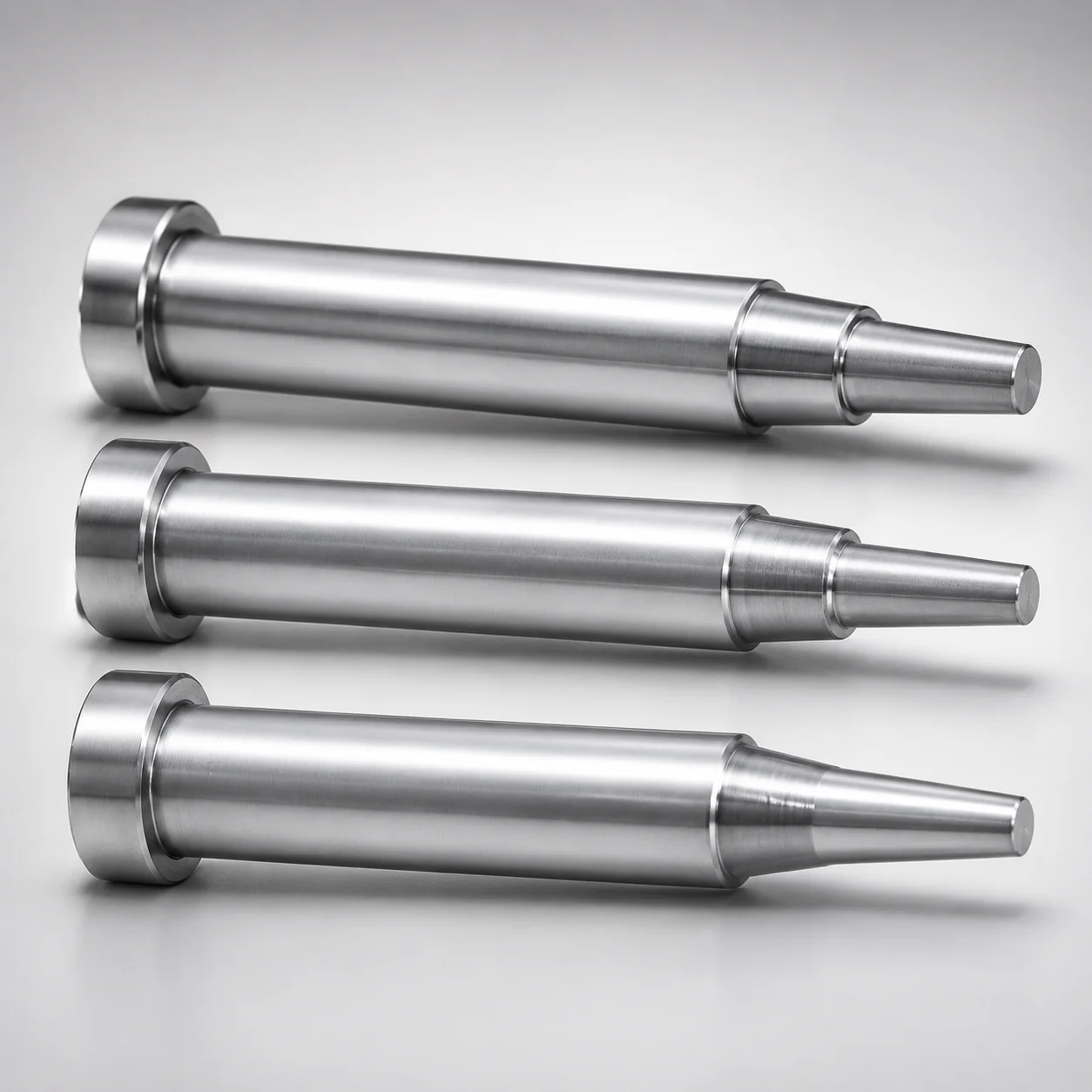
Two-Step Core Pins Head T=4 mm
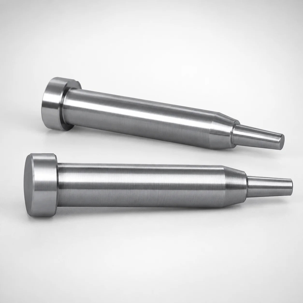
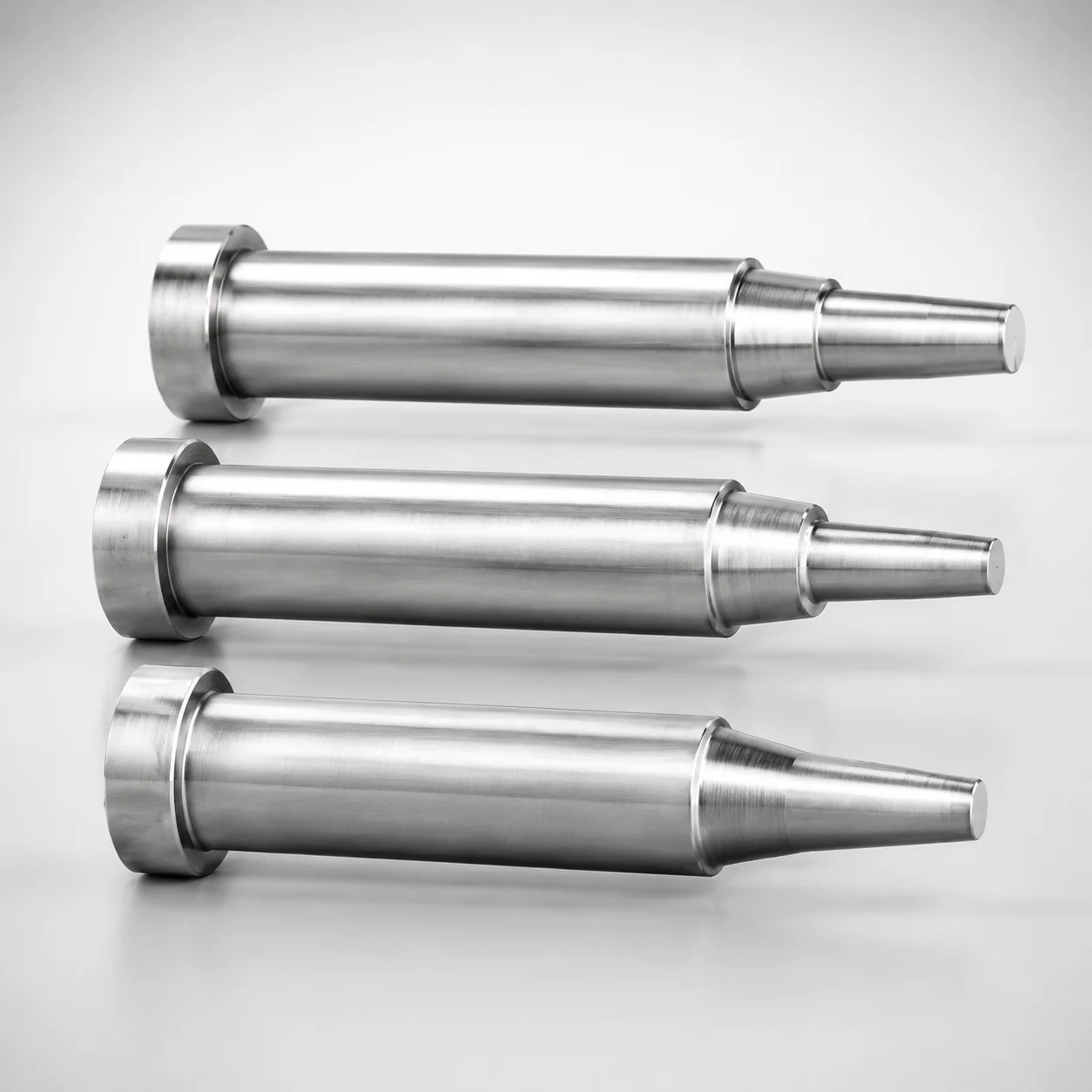
Two-Step core pins (Head T=4 mm) are designed for precise mold positioning, providing stable support from the two-step geometry. The controlled tolerances help maintain repeatable alignment during production runs.
- Two-step shape supports consistent core-to-bushing alignment
- High tolerance control for shaft Shaft Diameter 0/-0.005
- Length accuracy with L dimension tolerance +0.02/0 for tight assemblies
- Manufactured with Head thickness 4 mm (T4) for reliable fit in mold structures
Specifications
2249 configurations available
| Material | D/P (Shaft Diameter) (mm) | First Step Shape | Second Step Shape | A (Type of the first step diameter) (mm) | C (First step shape taper width) (mm) | E (Tip diameter) (mm) | F (Bearing bore length) (mm) | G (C chamfering width of the second step shape) (mm) | J (Type of the second step) (mm) | L (L dimension) (mm) | Q (Second step shape R chamfering) (mm) | R (First step type R) (mm) | V (Type of the second step) (mm) | Dimension Y (mm) | type |
|---|---|---|---|---|---|---|---|---|---|---|---|---|---|---|---|
| DH2F | 1 | CA | A | - | - | 0.5 ~ 0.98 | 10 ~ 98.9 | - | - | 12 ~ 100 | - | - | 0.51 ~ 0.99 | 10.5 ~ 99.5 | - |
| DH2F | 1.5 | CA | A | - | - | 0.5 ~ 1.48 | 10 ~ 99.5 | - | - | 12 ~ 100 | - | - | 0.5 ~ 1.49 | 10 ~ 99.5 | - |
| DH2F | 2 | CA | A | - | - | 0.7 ~ 1.98 | 10 ~ 99.5 | - | - | 12 ~ 100 | - | - | 0.7 ~ 1.99 | 10 ~ 99.5 | - |
| DH2F | 2.5 | CA | A | - | - | 0.7 ~ 2.48 | 10 ~ 99.5 | - | - | 12 ~ 100 | - | - | 0.7 ~ 2.49 | 10 ~ 99.5 | - |
| DH2F | 3 | CA | A | - | - | 1 ~ 2.98 | 10 ~ 99.5 | - | - | 12 ~ 100 | - | - | 1 ~ 2.99 | 10 ~ 99.5 | - |
| DH2F | 3.5 | CA | A | - | - | 1 ~ 3.48 | 10 ~ 99.5 | - | - | 12 ~ 100 | - | - | 1 ~ 3.49 | 10 ~ 99.5 | - |
| DH2F | 4 | CA | A | - | - | 1 ~ 3.98 | 10 ~ 119.75 | - | - | 12 ~ 120 | - | - | 1 ~ 3.99 | 10 ~ 119.5 | - |
| DH2F | 4.5 | CA | A | - | - | 1.5 ~ 4.48 | 10 ~ 119.75 | - | - | 12 ~ 120 | - | - | 1.5 ~ 4.49 | 10 ~ 119.5 | - |
| DH2F | 5 | CA | A | - | - | 1.5 ~ 4.98 | 10 ~ 119.75 | - | - | 12 ~ 120 | - | - | 1.5 ~ 4.99 | 10 ~ 119.5 | - |
| DH2F | 5.5 | CA | A | - | - | 1.5 ~ 5.48 | 10 ~ 119.75 | - | - | 12 ~ 120 | - | - | 1.5 ~ 5.49 | 10 ~ 119.5 | - |
| DH2F | 6 | CA | A | - | - | 2 ~ 5.98 | 10 ~ 119.75 | - | - | 12 ~ 120 | - | - | 2 ~ 5.99 | 10 ~ 119.5 | - |
| DH2F | 6.5 | CA | A | - | - | 2 ~ 6.48 | 10 ~ 119.75 | - | - | 12 ~ 120 | - | - | 2 ~ 6.49 | 10 ~ 119.5 | - |
| DH2F | 7 | CA | A | - | - | 2 ~ 6.98 | 10 ~ 119.75 | - | - | 12 ~ 120 | - | - | 2 ~ 6.99 | 10 ~ 119.5 | - |
| DH2F | 8 | CA | A | - | - | 2 ~ 7.98 | 10 ~ 119.75 | - | - | 12 ~ 120 | - | - | 2 ~ 7.99 | 10 ~ 119.5 | - |
| DH2F | 10 | CA | A | - | - | 2 ~ 9.98 | 10 ~ 119.75 | - | - | 12 ~ 120 | - | - | 2 ~ 9.99 | 10 ~ 119.5 | - |
| DH2F | 13 | CA | A | - | - | 2.5 ~ 12.98 | 10 ~ 119.75 | - | - | 12 ~ 120 | - | - | 2.5 ~ 12.99 | 10 ~ 119.5 | - |
| DH2F | 16 | CA | A | - | - | 2.5 ~ 15.98 | 10 ~ 119.75 | - | - | 12 ~ 120 | - | - | 2.5 ~ 15.99 | 10 ~ 119.5 | - |
| DH2F | 1 | CA | B | - | - | 0.5 ~ 0.98 | 10 ~ 98.8 | - | 0.5 ~ 0.98 | 12 ~ 100 | - | - | 0.51 ~ 0.99 | 10.5 ~ 99.5 | - |
| DH2F | 1.5 | CA | B | - | - | 0.5 ~ 1.48 | 10 ~ 99.5 | - | 0.5 ~ 1.48 | 12 ~ 100 | - | - | 0.51 ~ 1.49 | 10 ~ 99.5 | - |
| DH2F | 2 | CA | B | - | - | 0.7 ~ 1.98 | 10 ~ 99.5 | - | 0.7 ~ 1.98 | 12 ~ 100 | - | - | 0.71 ~ 1.99 | 10 ~ 99.5 | - |
| DH2F | 2.5 | CA | B | - | - | 0.7 ~ 2.48 | 10 ~ 99.5 | - | 0.7 ~ 2.48 | 12 ~ 100 | - | - | 0.71 ~ 2.49 | 10 ~ 99.5 | - |
| DH2F | 3 | CA | B | - | - | 1 ~ 2.98 | 10 ~ 99.5 | - | 1 ~ 2.98 | 12 ~ 100 | - | - | 1.01 ~ 2.99 | 10 ~ 99.5 | - |
| DH2F | 3.5 | CA | B | - | - | 1 ~ 3.48 | 10 ~ 99.5 | - | 1 ~ 3.48 | 12 ~ 100 | - | - | 1.01 ~ 3.49 | 10 ~ 99.5 | - |
| DH2F | 4 | CA | B | - | - | 1 ~ 3.98 | 10 ~ 119.75 | - | 1 ~ 3.98 | 12 ~ 120 | - | - | 1.01 ~ 3.99 | 10 ~ 119.5 | - |
| DH2F | 4.5 | CA | B | - | - | 1.5 ~ 4.48 | 10 ~ 119.75 | - | 1.5 ~ 4.48 | 12 ~ 120 | - | - | 1.51 ~ 4.49 | 10 ~ 119.5 | - |
| DH2F | 5 | CA | B | - | - | 1.5 ~ 4.98 | 10 ~ 119.75 | - | 1.5 ~ 4.98 | 12 ~ 120 | - | - | 1.51 ~ 4.99 | 10 ~ 119.5 | - |
| DH2F | 5.5 | CA | B | - | - | 1.5 ~ 5.48 | 10 ~ 119.75 | - | 1.5 ~ 5.48 | 12 ~ 120 | - | - | 1.51 ~ 5.49 | 10 ~ 119.5 | - |
| DH2F | 6 | CA | B | - | - | 2 ~ 5.98 | 10 ~ 119.75 | - | 2 ~ 5.98 | 12 ~ 120 | - | - | 2.01 ~ 5.99 | 10 ~ 119.5 | - |
| DH2F | 6.5 | CA | B | - | - | 2 ~ 6.48 | 10 ~ 119.75 | - | 2 ~ 6.48 | 12 ~ 120 | - | - | 2.01 ~ 6.49 | 10 ~ 119.5 | - |
| DH2F | 7 | CA | B | - | - | 2 ~ 6.98 | 10 ~ 119.75 | - | 2 ~ 6.98 | 12 ~ 120 | - | - | 2.01 ~ 6.99 | 10 ~ 119.5 | - |
| DH2F | 8 | CA | B | - | - | 2 ~ 7.98 | 10 ~ 119.75 | - | 2 ~ 7.98 | 12 ~ 120 | - | - | 2.01 ~ 7.99 | 10 ~ 119.5 | - |
| DH2F | 10 | CA | B | - | - | 2 ~ 9.98 | 10 ~ 119.75 | - | 2 ~ 9.98 | 12 ~ 120 | - | - | 2.01 ~ 9.99 | 10 ~ 119.5 | - |
| DH2F | 13 | CA | B | - | - | 2.5 ~ 12.98 | 10 ~ 119.75 | - | 2.5 ~ 12.98 | 12 ~ 120 | - | - | 2.51 ~ 12.99 | 10 ~ 119.5 | - |
| DH2F | 16 | CA | B | - | - | 2.5 ~ 15.98 | 10 ~ 119.75 | - | 2.5 ~ 15.98 | 12 ~ 120 | - | - | 2.51 ~ 15.99 | 10 ~ 119.5 | - |
| DH2F | 1 | CA | C | - | - | 0.5 ~ 0.98 | 10 ~ 98.9 | - | 0.5 ~ 0.98 | 12 ~ 100 | - | - | 0.51 ~ 0.99 | 10.5 ~ 99.5 | - |
| DH2F | 1.5 | CA | C | - | - | 0.5 ~ 1.48 | 10 ~ 99.5 | - | 0.5 ~ 1.48 | 12 ~ 100 | - | - | 0.51 ~ 1.49 | 10 ~ 99.5 | - |
| DH2F | 2 | CA | C | - | - | 0.7 ~ 1.98 | 10 ~ 99.5 | - | 0.7 ~ 1.98 | 12 ~ 100 | - | - | 0.71 ~ 1.99 | 10 ~ 99.5 | - |
| DH2F | 2.5 | CA | C | - | - | 0.7 ~ 2.48 | 10 ~ 99.5 | - | 0.7 ~ 2.48 | 12 ~ 100 | - | - | 0.71 ~ 2.49 | 10 ~ 99.5 | - |
| DH2F | 3 | CA | C | - | - | 1 ~ 2.98 | 10 ~ 99.5 | - | 1 ~ 2.98 | 12 ~ 100 | - | - | 1.01 ~ 2.99 | 10 ~ 99.5 | - |
| DH2F | 3.5 | CA | C | - | - | 1 ~ 3.48 | 10 ~ 99.5 | - | 1 ~ 3.48 | 12 ~ 100 | - | - | 1.01 ~ 3.49 | 10 ~ 99.5 | - |
| DH2F | 4 | CA | C | - | - | 1 ~ 3.98 | 10 ~ 119.75 | - | 1 ~ 3.98 | 12 ~ 120 | - | - | 1.01 ~ 3.99 | 10 ~ 119.5 | - |
| DH2F | 4.5 | CA | C | - | - | 1.5 ~ 4.48 | 10 ~ 119.75 | - | 1.5 ~ 4.48 | 12 ~ 120 | - | - | 1.51 ~ 4.49 | 10 ~ 119.5 | - |
| DH2F | 5 | CA | C | - | - | 1.5 ~ 4.98 | 10 ~ 119.75 | - | 1.5 ~ 4.98 | 12 ~ 120 | - | - | 1.51 ~ 4.99 | 10 ~ 119.5 | - |
| DH2F | 5.5 | CA | C | - | - | 1.5 ~ 5.48 | 10 ~ 119.75 | - | 1.5 ~ 5.48 | 12 ~ 120 | - | - | 1.51 ~ 5.49 | 10 ~ 119.5 | - |
| DH2F | 6 | CA | C | - | - | 2 ~ 5.98 | 10 ~ 119.75 | - | 2 ~ 5.98 | 12 ~ 120 | - | - | 2.01 ~ 5.99 | 10 ~ 119.5 | - |
| DH2F | 6.5 | CA | C | - | - | 2 ~ 6.48 | 10 ~ 119.75 | - | 2 ~ 6.48 | 12 ~ 120 | - | - | 2.01 ~ 6.49 | 10 ~ 119.5 | - |
| DH2F | 7 | CA | C | - | - | 2 ~ 6.98 | 10 ~ 119.75 | - | 2 ~ 6.98 | 12 ~ 120 | - | - | 2.01 ~ 6.99 | 10 ~ 119.5 | - |
| DH2F | 8 | CA | C | - | - | 2 ~ 7.98 | 10 ~ 119.75 | - | 2 ~ 7.98 | 12 ~ 120 | - | - | 2.01 ~ 7.99 | 10 ~ 119.5 | - |
| DH2F | 10 | CA | C | - | - | 2 ~ 9.98 | 10 ~ 119.75 | - | 2 ~ 9.98 | 12 ~ 120 | - | - | 2.01 ~ 9.99 | 10 ~ 119.5 | - |
| DH2F | 13 | CA | C | - | - | 2.5 ~ 12.98 | 10 ~ 119.75 | - | 2.5 ~ 12.98 | 12 ~ 120 | - | - | 2.51 ~ 12.99 | 10 ~ 119.5 | - |
Product Guide
Application Scenarios+
Two-step core pins with a 4 mm head thickness are used in injection mold tooling where the core must be positioned and supported with high repeatability. The stepped geometry provides a controlled seating action, helping maintain stable core-to-bushing alignment during production.
In automotive connector and housing molds, these pins support precise core alignment for thin-wall features. The tightened shaft diameter specification (0/−0.005 mm) helps ensure consistent fit through the steel guide structure, supporting smooth, reliable ejection.
In electrical appliance and precision casing molds, the two-step bearing area supports load distribution while limiting lateral play. The controlled L dimension tolerance (+0.02/0 mm) helps lock stack-up consistency across multiple cavities or components.
- Use where stable ejection and alignment depend on tight shaft-to-bushing clearance.
- Choose the specified step shapes (first/second step options) to match your core-to-support layout.
Material & Process Details+
This stepped core pin series is available in several common mold steels, selected for wear resistance and dimensional stability in guide and support roles. Options include SKH51 (AISI M2 equivalent), SKD61 (AISI H13 equivalent), NAK80 (corrosion-resistant, pre-hardened tool steel), DH2F, SUS440C, and MAS1C.
Hardness and performance depend on the selected grade and its heat treatment state. In general, high-hardness grades (e.g., tool steels such as SKH51 or SKD61 after proper heat treatment) offer improved wear resistance, while maintaining toughness through controlled tempering to avoid brittleness in ejection/guide cycling.
- Select quenched & tempered tool steels when higher abrasion resistance is required.
- Select corrosion-resistant grades (e.g., NAK80) when surface stability in humid or chemically active environments matters.
- For long-life guide surfaces, confirm heat-treatment and target hardness for the intended cycle rate.
Sizing & Selection Guide+
Correct selection starts with matching the shaft diameter D/P (1–20 mm) to your core bore or bushing fit requirement. This series specifies shaft diameter tolerance of 0/−0.005 mm, so confirm whether your mating bushing bore expects a near-zero clearance or intentional interference-free guidance.
Next, set the overall functional length using the L dimension (12–150 mm, depending on configuration). The L tolerance is +0.02/0 mm, meaning length will not be shorter than nominal, which supports tight stack-ups in cavity/core assemblies.
- Choose the first step diameter type A (0.51–5 mm) and the first-step geometry (CA/CB/CC/CD/CE) to match the seating diameter on your core side.
- Select the second step shape (A/B/C/D/E) and tip diameter E (0.5–5 mm) to align with the guide/support profile.
- Verify bearing bore length F (10–30 mm) and chamfer widths (e.g., G 0.1–0.5 / 0.1–0.2) for smooth assembly and reduced stress concentration.
If you are varying step shapes, treat step dimensions as configurable while the head thickness is fixed at T = 4 mm for this variant.
Frequently Asked Questions
What shaft diameter tolerance should I design for when using this two-step core pin series?+
The shaft diameter D/P range is 1–20 mm with a tolerance of 0/−0.005 mm. This means the pin diameter can be up to nominal, but may be slightly smaller by 0.005 mm. Size the mating bushing/core bore to maintain the intended guidance clearance across production lots.
How does the L dimension tolerance affect core stack-up in multi-cavity molds?+
The L dimension range is configuration-dependent (e.g., 12–100, 12–120, 12–150, or up to 30–150). Its tolerance is +0.02/0 mm, so the pin length will not be shorter than nominal. This helps preserve repeatable stack-up positioning when multiple pins support a core.
Which material grades are appropriate if I need higher wear resistance on guide surfaces?+
Material options include SKH51 (AISI M2 equivalent) and SKD61 (AISI H13 equivalent), both commonly selected for tougher, wear-resistant tool steel applications. The final wear performance depends on the selected grade and its heat treatment/tempering. For corrosive conditions, NAK80 is typically chosen among the provided options.
How do I choose between the first-step shapes (CA/CB/CC/CD/CE) and second-step shapes (A/B/C/D/E)?+
First-step shape options (CA/CB/CC/CD/CE) control the first step geometry, while second-step shape options (A/B/C/D/E) define the mating profile on the support side. Use the A (0.51–5 mm), E (0.5–5 mm), and tip/step feature dimensions to match your bushing/core seating surfaces. The selection should reflect how you want the pin to control alignment under load.
Is the 4 mm head thickness configurable for this part number?+
No. This variant is defined as Two-Step Core Pins Head T = 4 mm, so the head thickness is fixed. Other geometric features such as step shapes and shaft diameter (1–20 mm) are configured per specification, but T remains 4 mm.
Related Products
Need Custom Specifications?
Our engineering team can help with custom configurations, material selection, and volume pricing.