Angled Pins
High precision angled pins for injection molding undercuts, providing precise kinematics and durability.
Available Angled Pins
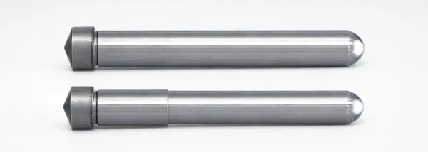
Flange Angled Angular Pins
Flange angled angular pins for precise mold alignment, available in straight or stepped styles with selectable press-fit diameters.
View Details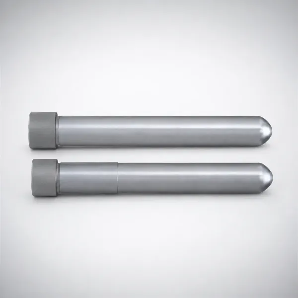
DIN Standard Steel Flange Angle Pins Stepped Type
Flange angle pins (stepped type) for positive, non-taper mounting. Steel construction supports stable press-fit performance.
View Details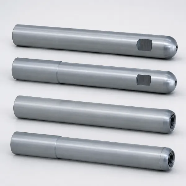
Angular Pins Tapped Hexagonal Socket Stepped Type
Angular Pins Tapped Hexagonal Socket Stepped Type for secure fastening in angular assemblies.
View Details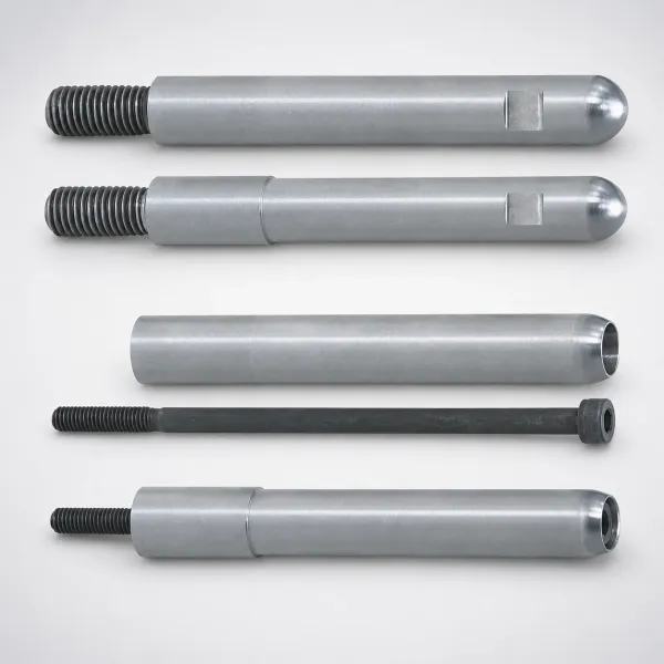
Angular Pins With Male Thread, Hex Socket Bolt
Angular Pins With Male Thread, Hex Socket Bolt for secure fastening and alignment in tight assemblies.
View Details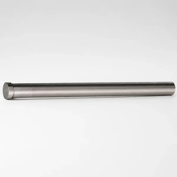
Inch Radius Angle Pins Nitrided Hotwork Steel
Radius Angle Pins for inch slides and lifters, precision ground from hotwork steel and nitrided for wear resistance.
View Details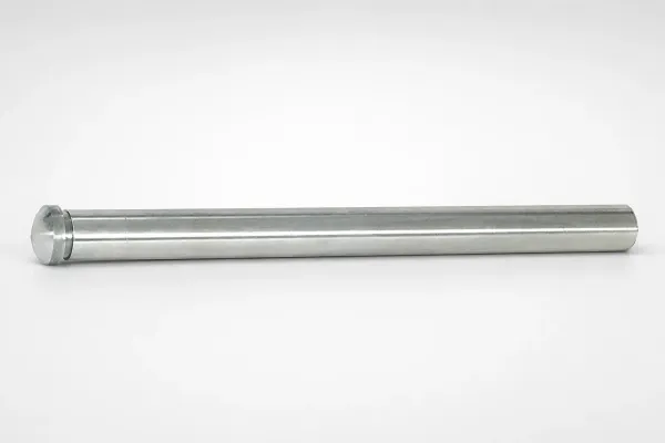
Hotwork Steel Radius Angle Pins - Nitrided
Radius Angle Pins with precision-ground hotwork steel and nitrided surface hardness for reliable press-fit positioning.
View DetailsApplication Scenarios
Selecting the correct angled pin depends on the required stroke length, core mass, and allowable mold space.
Standard Slide Core Actuation
For standard slide strokes (10-30mm) where the slide core mass is under 5kg. Typically requires angles between 15° and 20°.
Compact Mold Base Layouts
When mold height is restricted and standard pins protrude too far. Requires stepped or short-head designs to avoid interference with the clamp plate.
Angle-Stroke Geometry & Kinematics
The relationship between pin angle, mold opening stroke, and slide stroke is the foundational calculation for any angled pin design.
Fundamental Stroke Formula
The slide stroke (S) is dictated by the mold opening stroke (H) and the pin angle (θ) according to the formula: S = H × tan(θ). It is generally recommended to keep θ between 10° and 25°. Exceeding 25° results in excessive bending moments on the pin and unacceptably high friction on the slide wear plates.
Clearance and Tolerance
To prevent the pin from binding against the slide block during the initial mold opening shock, the angled hole in the slide should be 0.5mm to 1.0mm larger than the pin diameter. Furthermore, the pin angle must be 2° to 3° smaller than the locking block wedge angle to ensure the lock block releases before the pin begins to pull the slide.
Technical Resources
Need a Custom Quote?
Send your specifications and receive a quote. MOQ: 1 piece. Custom dimensions available.