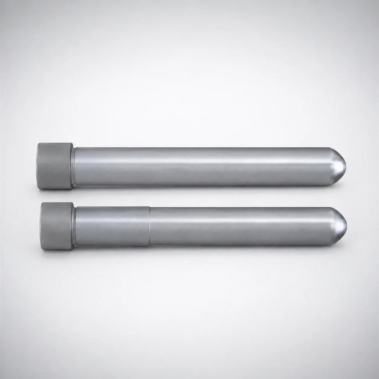
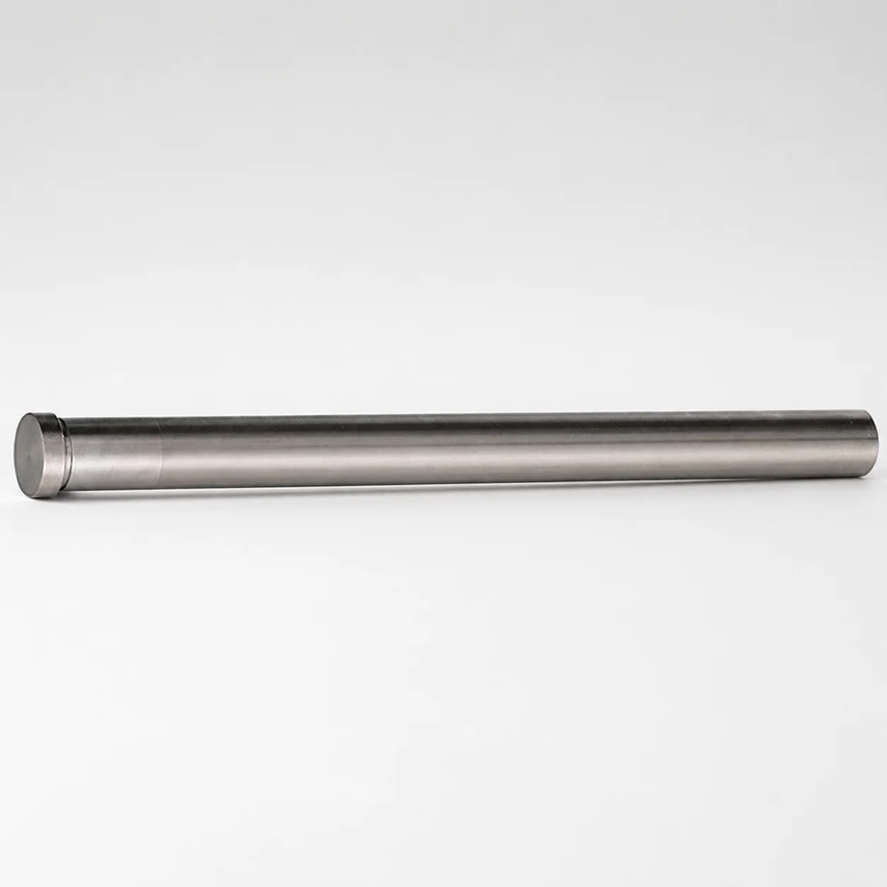
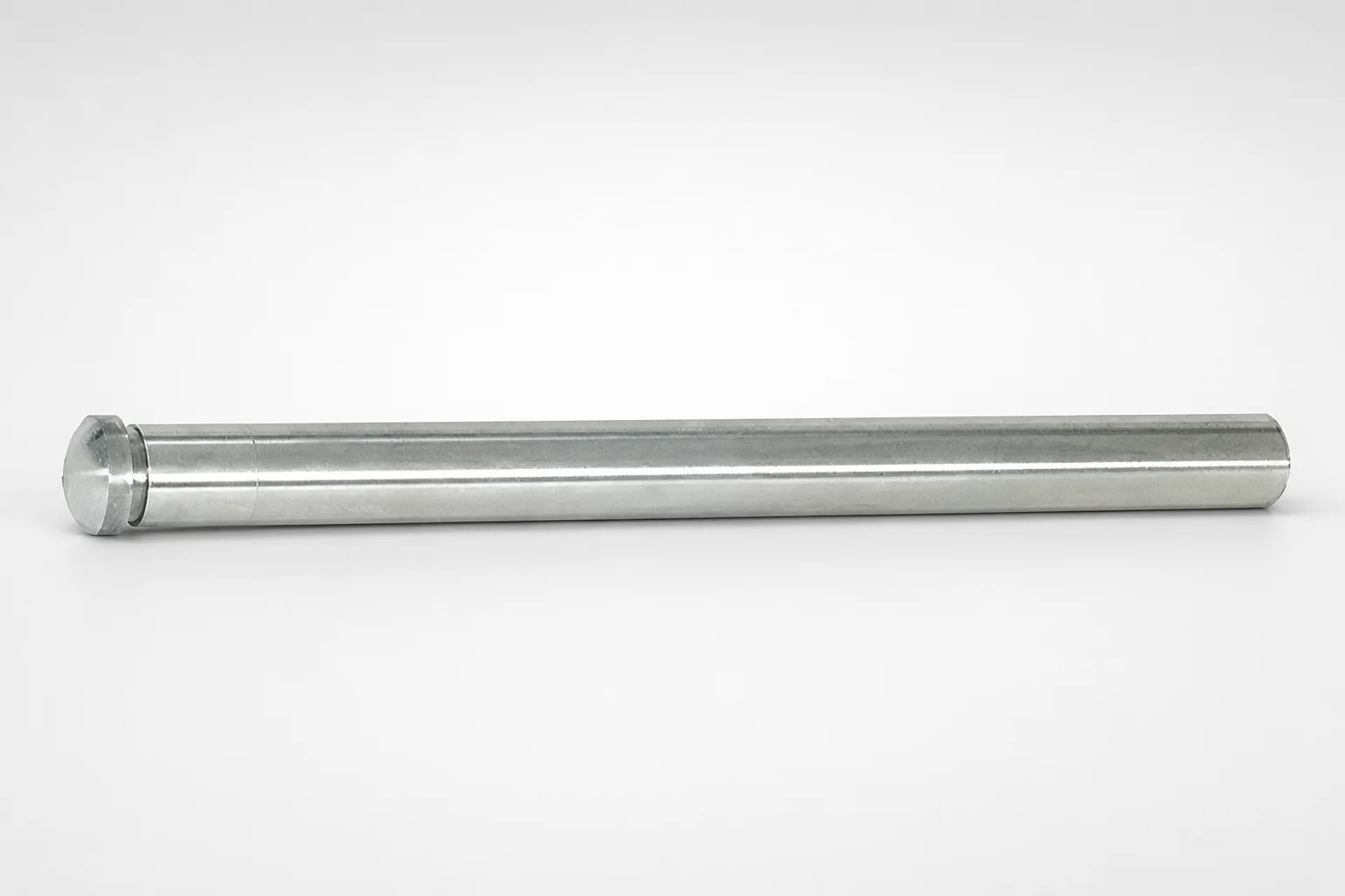
DIN Standard Steel Flange Angle Pins Stepped Type
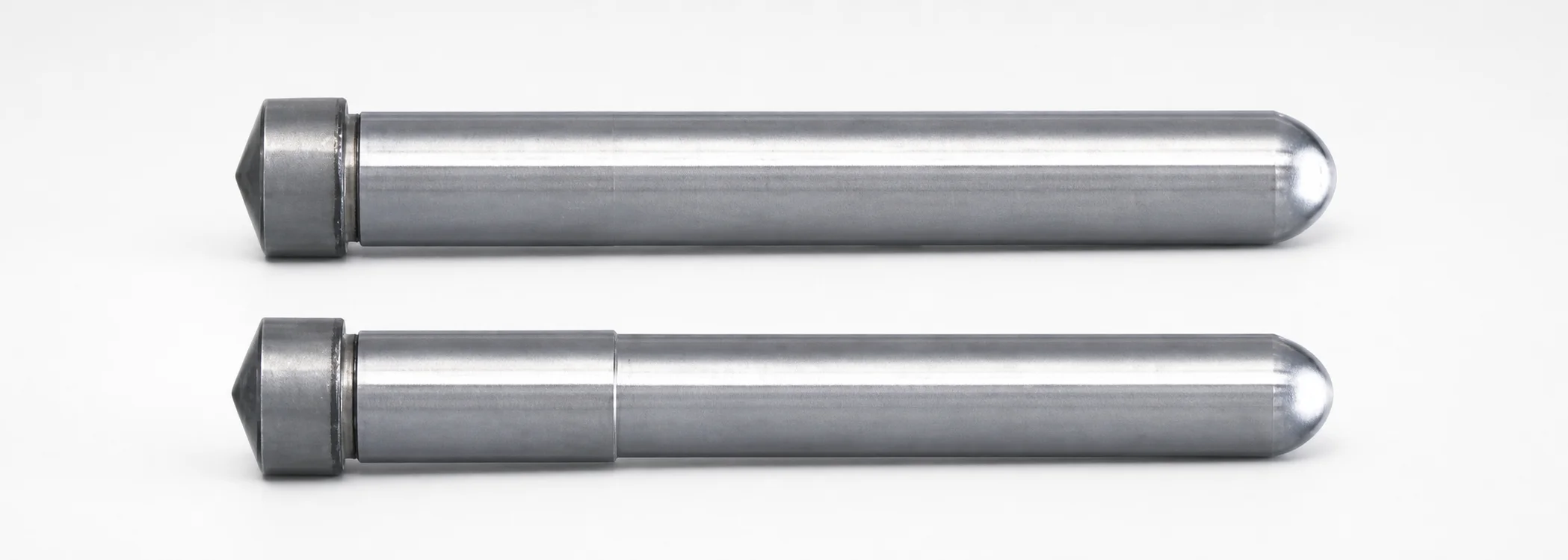
Flange angle pins (stepped type) are engineered for positive alignment in fixtures and jigs using a non-taper flange mounting style. The stepped geometry helps locate parts consistently during repeated assembly and setup.
- Flange (not tapered) mounting for reliable positioning without rotational play
- Steel construction with wear-resistant performance for long production runs
- Stepped option supports controlled engagement for stable press-fit length seating
- Designed to suit tooling applications needing repeatable angle alignment
Specifications
52 configurations available
| Shape | D (Diameter) (mm) | L (Length) (mm) | LC (Length alteration) (mm) | N (Press-fit length) (mm) | type |
|---|---|---|---|---|---|
| Straight | 8 | 40 ~ 110 | - | 0 | - |
| Straight | 8 | 40 ~ 110 | - | 2 ~ 110 | - |
| Straight | 8 | - | 40.1 ~ 109.9 | 0 | - |
| Straight | 8 | - | 40.1 ~ 109.9 | 2 ~ 110 | - |
| Straight | 10 | 40 ~ 110 | - | 0 | - |
| Straight | 10 | 40 ~ 110 | - | 2 ~ 110 | - |
| Straight | 10 | - | 40.1 ~ 109.9 | 0 | - |
| Straight | 10 | - | 40.1 ~ 109.9 | 2 ~ 110 | - |
| Straight | 12 | 50 ~ 130 | - | 0 | - |
| Straight | 12 | 50 ~ 130 | - | 2 ~ 130 | - |
| Straight | 12 | - | 50.1 ~ 129.9 | 0 | - |
| Straight | 12 | - | 50.1 ~ 129.9 | 2 ~ 130 | - |
| Straight | 13 | 50 ~ 130 | - | 0 | - |
| Straight | 13 | 50 ~ 130 | - | 2 ~ 130 | - |
| Straight | 13 | - | 50.1 ~ 129.9 | 0 | - |
| Straight | 13 | - | 50.1 ~ 129.9 | 2 ~ 130 | - |
| Straight | 15 | 70 ~ 140 | - | 0 | - |
| Straight | 15 | 70 ~ 140 | - | 2 ~ 140 | - |
| Straight | 15 | - | 70.1 ~ 139.9 | 0 | - |
| Straight | 15 | - | 70.1 ~ 139.9 | 2 ~ 140 | - |
| Straight | 16 | 70 ~ 140 | - | 0 | - |
| Straight | 16 | 70 ~ 140 | - | 2 ~ 140 | - |
| Straight | 16 | - | 70.1 ~ 139.9 | 0 | - |
| Straight | 16 | - | 70.1 ~ 139.9 | 2 ~ 140 | - |
| Stepped | 8 | 40 ~ 110 | - | 0 | - |
| Stepped | 8 | 40 ~ 110 | - | 2 ~ 110 | - |
| Stepped | 8 | - | 40.1 ~ 109.9 | 0 | - |
| Stepped | 8 | - | 40.1 ~ 109.9 | 2 ~ 110 | - |
| Stepped | 10 | 40 ~ 110 | - | 0 | - |
| Stepped | 10 | 40 ~ 110 | - | 2 ~ 110 | - |
| Stepped | 10 | - | 40.1 ~ 109.9 | 0 | - |
| Stepped | 10 | - | 40.1 ~ 109.9 | 2 ~ 110 | - |
| Stepped | 12 | 50 ~ 130 | - | 0 | - |
| Stepped | 12 | 50 ~ 130 | - | 2 ~ 130 | - |
| Stepped | 12 | - | 50.1 ~ 129.9 | 0 | - |
| Stepped | 12 | - | 50.1 ~ 129.9 | 2 ~ 130 | - |
| Stepped | 13 | 50 ~ 130 | - | 0 | - |
| Stepped | 13 | 50 ~ 130 | - | 2 ~ 130 | - |
| Stepped | 13 | - | 50.1 ~ 129.9 | 0 | - |
| Stepped | 13 | - | 50.1 ~ 129.9 | 2 ~ 130 | - |
| Stepped | 15 | 70 ~ 140 | - | 0 | - |
| Stepped | 15 | 70 ~ 140 | - | 2 ~ 140 | - |
| Stepped | 15 | - | 70.1 ~ 139.9 | 0 | - |
| Stepped | 15 | - | 70.1 ~ 139.9 | 2 ~ 140 | - |
| Stepped | 16 | 70 ~ 140 | - | 0 | - |
| Stepped | 16 | 70 ~ 140 | - | 2 ~ 140 | - |
| Stepped | 16 | - | 70.1 ~ 139.9 | 0 | - |
| Stepped | 16 | - | 70.1 ~ 139.9 | 2 ~ 140 | - |
| Stepped | 20 | 90 ~ 180 | - | 0 | - |
| Stepped | 20 | 90 ~ 180 | - | 2 ~ 180 | - |
Product Guide
Application Scenarios+
Stepped flange angle pins are used in injection mold tooling to lock alignment between moving components and assembly fixtures where a repeatable angle reference is critical. The non-taper, flange mounting style helps achieve positive, rotation-resistant location during press assembly.
- Automotive connector and terminal molds: In tooling that cycles at high frequency, the stepped engagement supports stable press-fit length seating, helping maintain consistent core/cavity alignment and reducing mismatch risk during setup changes.
- Electronics housing and insert molds: When tooling requires fixture repeatability for parting line registration, the straight/stepped geometry with controlled press-fit length selection supports repeatable positioning without relying on taper features.
- Medical device housing and precision packaging molds: The flange (not tapered) approach is suited for fixtures and jigs that must prevent rotational play, supporting consistent alignment through multiple assembly events.
Choose this stepped variant when your design benefits from controlled seating length and positive, non-taper alignment rather than friction-only location.
Material & Process Details+
This series is specified as steel construction, selected to provide stable press-fit performance under repeated assembly and tooling wear. For angle-pin applications, the key property is balancing wear resistance (to resist fretting and surface deformation at the flange interface) with adequate toughness to tolerate handling and insertion loads.
- Hardness / heat treatment: The provided data does not list an HRC value or a specific heat-treatment state (e.g., quenched & tempered, nitrided). Therefore, confirm the exact supplier spec (heat treatment and target hardness) for your tolerance-critical builds.
- Wear vs. toughness trade-off: Harder states generally improve wear resistance of the press-fit region, while lower hardness can improve tolerance to impact or assembly shock.
Because the input does not provide multiple steel grades, comparisons between material options are not supported for this SKU.
Sizing & Selection Guide+
Select dimensions to match both the overall pin length and the required press-fit engagement in your mold or fixture. Use the provided ranges to choose the closest diameter and length combination, then verify the length alteration (LC) corresponds to your installation stack-up.
- Diameter (D): Available from 8 to 20 mm. Choose D based on the reamed/reamless hole size in the mold base or locating plates.
- Length (L): Offered as grouped ranges: 40–110, 50–130, 70–140, and 90–180 mm. Match L to the required insertion depth and clearance.
- Press-fit length (N): Options include 0 and stepped engagement variants of 2–110, 2–130, 2–140, and 2–180 mm. Set N so the flange interface seats properly without bottoming.
- Length alteration (LC): Available in corresponding ranges (e.g., 40.1–109.9, 50.1–129.9, 70.1–139.9, 90.1–179.9) to fine-tune fit.
Use LC to control the final effective length in your cavity/core assembly. Tolerance details are not provided in the data—validate press-fit clearance with your hole tolerance spec.
Frequently Asked Questions
How do I choose the press-fit length (N) for a stepped flange angle pin in my mold base?+
Use the provided N (press-fit length) options to set the engagement depth: 0, 2–110, 2–130, 2–140, or 2–180 mm. Pair N with the selected overall L range (e.g., 40–110 or 90–180 mm) to ensure the flange seats correctly without bottoming.
What diameter (D) range is available, and how should it relate to my locating hole size?+
The pin diameter D is available from 8 to 20 mm. Select D to match the reamed hole or locating bore in your fixture/mold plate, then confirm press-fit clearance using your hole tolerance and the supplier’s fit recommendation (not included in the provided data).
What is the practical difference between L and LC when configuring this stepped pin?+
L is the overall length selection, while LC (length alteration) provides an available adjusted-length range close to L (e.g., 40.1–109.9 for the 40–110 group). Use LC to fine-tune the final effective length against your assembly stack-up and clearance constraints.
Is this pin intended for non-taper mounting, and why does that matter for alignment repeatability?+
This design uses a flange (not tapered) mounting style for positive, non-taper location. Avoiding taper features helps reduce the risk of rotational play during repeated assembly and setup, improving consistency of angle reference in tooling fixtures.
Do you have hardness (HRC) or heat-treatment data for this steel angle-pin series?+
The provided specifications confirm steel construction but do not list an HRC hardness value or a specific heat-treatment state (such as quenched & tempered or nitriding). For designs requiring verified wear/deflection performance, request the exact heat-treatment and hardness certificate for this SKU/lot.
Related Products
Need Custom Specifications?
Our engineering team can help with custom configurations, material selection, and volume pricing.