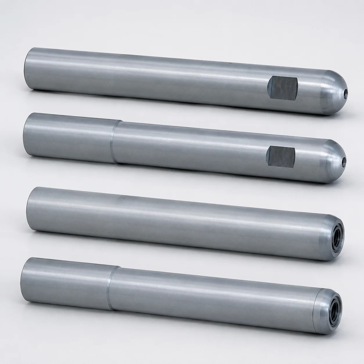
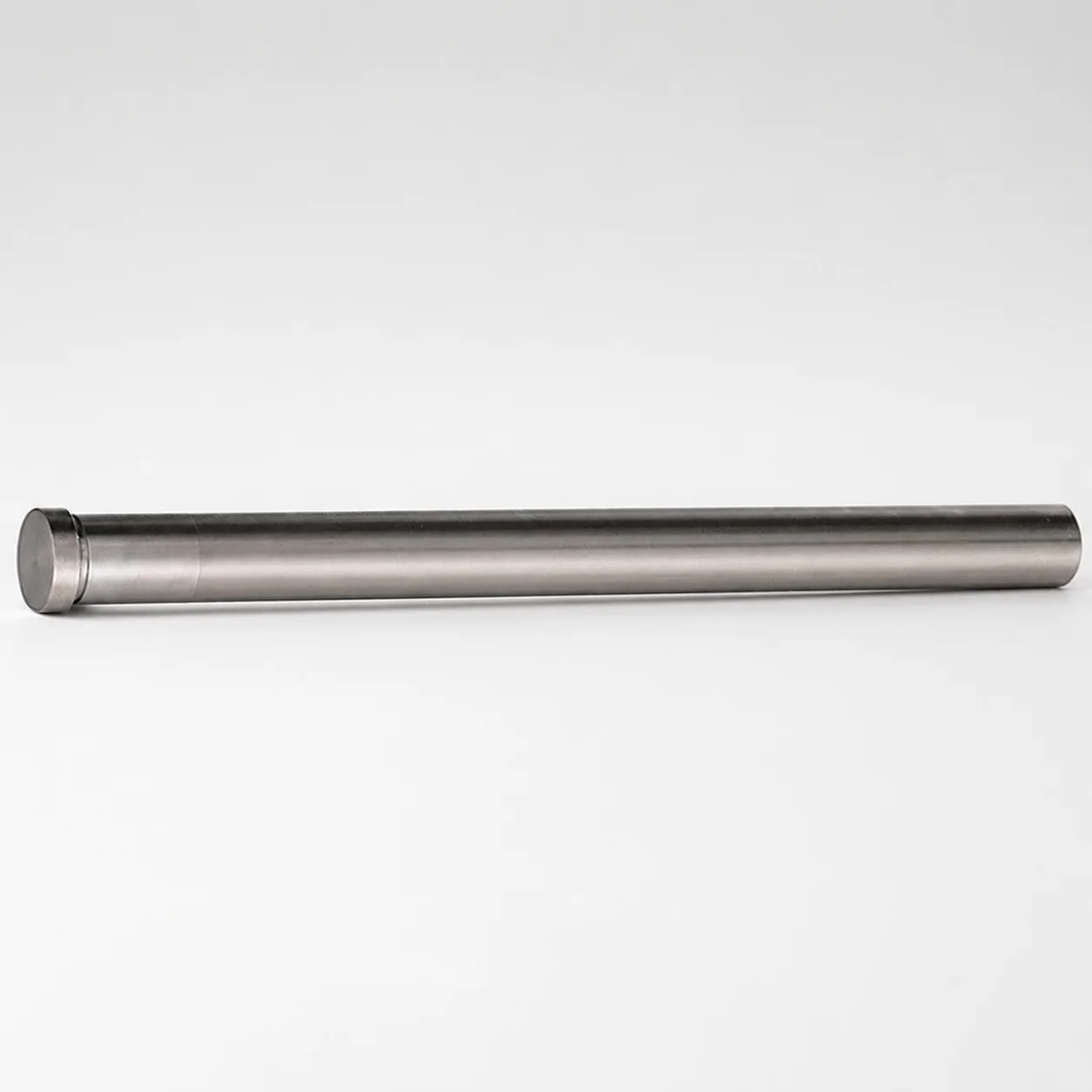
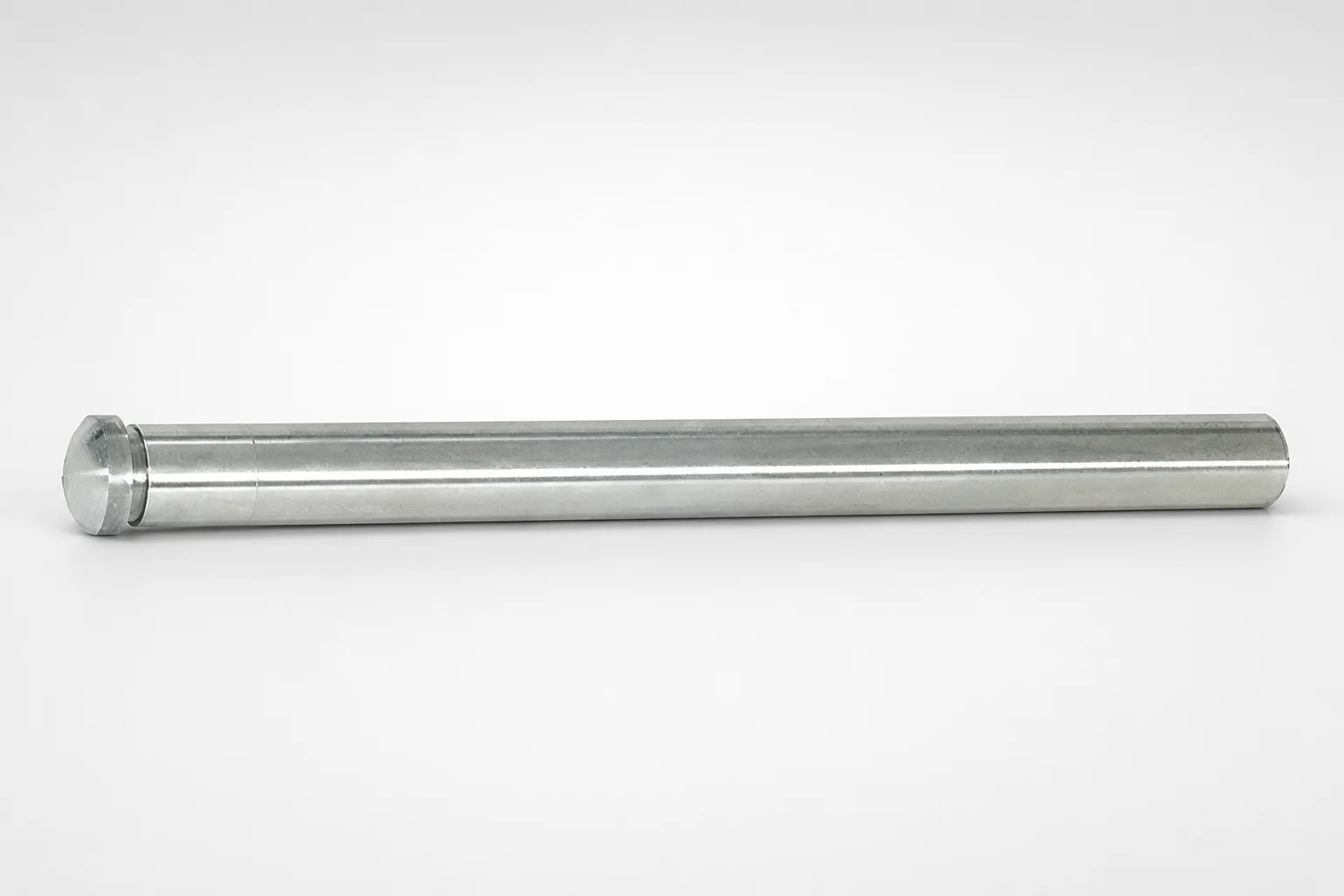
Angular Pins Tapped Hexagonal Socket Stepped Type
Angular pins tapped hexagonal socket stepped type are engineered for secure clamping and consistent alignment in angled mechanical assemblies. The stepped form helps positioning during installation while the tapped socket supports controlled fastening with the right wrench system.
- Tapped mounting for spanner/hexagonal wrench fastening in angled setups
- Stepped pin geometry improves positional control during assembly
- Used for radius/angled configurations to support stable component alignment
- Designed for industrial equipment where minimizing loosening and wear matters
Specifications
40 configurations available
| Mounting Type | Shape | D (Diameter) (mm) | L (Length) (mm) | N (Dh7 section length) (mm) | type |
|---|---|---|---|---|---|
| Tapped, for hexagonal wrench | Straight | 10 | 30 ~ 200 | 0 ~ 200 | - |
| Tapped, for hexagonal wrench | Straight | 12 | 35 ~ 250 | 0 ~ 250 | - |
| Tapped, for hexagonal wrench | Straight | 13 | 35 ~ 250 | 0 ~ 250 | - |
| Tapped, for hexagonal wrench | Straight | 16 | 45 ~ 250 | 0 ~ 250 | - |
| Tapped, for hexagonal wrench | Straight | 20 | 50 ~ 350 | 0 ~ 250 | - |
| Tapped, for hexagonal wrench | Straight | 25 | 50 ~ 400 | 0 ~ 350 | - |
| Tapped, for hexagonal wrench | Straight | 30 | 60 ~ 400 | 0 ~ 400 | - |
| Tapped, for hexagonal wrench | Straight | 32 | 60 ~ 400 | 0 ~ 400 | - |
| Tapped, for hexagonal wrench | Straight | 35 | 60 ~ 450 | 0 ~ 400 | - |
| Tapped, for hexagonal wrench | Straight | 40 | 60 ~ 450 | 0 ~ 400 | - |
| Tapped, for hexagonal wrench | Stepped | 10 | 30 ~ 200 | 0 ~ 200 | - |
| Tapped, for hexagonal wrench | Stepped | 12 | 35 ~ 250 | 0 ~ 250 | - |
| Tapped, for hexagonal wrench | Stepped | 13 | 35 ~ 250 | 0 ~ 250 | - |
| Tapped, for hexagonal wrench | Stepped | 16 | 45 ~ 250 | 0 ~ 250 | - |
| Tapped, for hexagonal wrench | Stepped | 20 | 50 ~ 350 | 0 ~ 250 | - |
| Tapped, for hexagonal wrench | Stepped | 25 | 50 ~ 400 | 0 ~ 350 | - |
| Tapped, for hexagonal wrench | Stepped | 30 | 60 ~ 400 | 0 ~ 400 | - |
| Tapped, for hexagonal wrench | Stepped | 32 | 60 ~ 400 | 0 ~ 400 | - |
| Tapped, for hexagonal wrench | Stepped | 35 | 60 ~ 450 | 0 ~ 400 | - |
| Tapped, for hexagonal wrench | Stepped | 40 | 60 ~ 450 | 0 ~ 400 | - |
| Tapped, for spanner | Straight | 10 | 30 ~ 200 | 0 ~ 200 | - |
| Tapped, for spanner | Straight | 12 | 35 ~ 250 | 0 ~ 250 | - |
| Tapped, for spanner | Straight | 13 | 35 ~ 250 | 0 ~ 250 | - |
| Tapped, for spanner | Straight | 16 | 45 ~ 250 | 0 ~ 250 | - |
| Tapped, for spanner | Straight | 20 | 50 ~ 350 | 0 ~ 250 | - |
| Tapped, for spanner | Straight | 25 | 50 ~ 400 | 0 ~ 350 | - |
| Tapped, for spanner | Straight | 30 | 60 ~ 400 | 0 ~ 400 | - |
| Tapped, for spanner | Straight | 32 | 60 ~ 400 | 0 ~ 400 | - |
| Tapped, for spanner | Straight | 35 | 60 ~ 450 | 0 ~ 400 | - |
| Tapped, for spanner | Straight | 40 | 60 ~ 450 | 0 ~ 400 | - |
| Tapped, for spanner | Stepped | 10 | 30 ~ 200 | 0 ~ 200 | - |
| Tapped, for spanner | Stepped | 12 | 35 ~ 250 | 0 ~ 250 | - |
| Tapped, for spanner | Stepped | 13 | 35 ~ 250 | 0 ~ 250 | - |
| Tapped, for spanner | Stepped | 16 | 45 ~ 250 | 0 ~ 250 | - |
| Tapped, for spanner | Stepped | 20 | 50 ~ 350 | 0 ~ 250 | - |
| Tapped, for spanner | Stepped | 25 | 50 ~ 400 | 0 ~ 350 | - |
| Tapped, for spanner | Stepped | 30 | 60 ~ 400 | 0 ~ 400 | - |
| Tapped, for spanner | Stepped | 32 | 60 ~ 400 | 0 ~ 400 | - |
| Tapped, for spanner | Stepped | 35 | 60 ~ 450 | 0 ~ 400 | - |
| Tapped, for spanner | Stepped | 40 | 60 ~ 450 | 0 ~ 400 | - |
Product Guide
Application Scenarios+
This stepped angular pin is used in injection mold tooling where reliable alignment and secure fastening are needed in angled or off-axis assemblies.
- Angled ejector or return mechanisms: The stepped geometry improves positioning during installation, helping maintain consistent engagement when the component stack is not perfectly vertical. The tapped, hexagonal-socket interface is suited for controlled tightening using the matching wrench system.
- Automotive and industrial appliance molds: In high-cycle tooling, secure fastening reduces the risk of loosening from vibration and repeated actuation. The stepped form provides better positional control, supporting stable alignment of angular sub-assemblies.
- Radius/angled alignment features: For molds with angular components or offset mounting faces, the tapped configuration allows repeatable fastening while the stepped profile helps maintain concentricity during maintenance.
With D = 10–40 mm and L = 30–60 mm, this variant can be matched to common angled pinning layouts to improve setup repeatability and reduce wear-related alignment drift.
Material & Process Details+
The provided specifications describe geometry and fastening interface, but no steel grade or heat-treatment state is listed for this series. Therefore, material-related values such as HRC hardness, nitriding/carburizing, or quenched-and-tempered treatment cannot be stated from the input data.
When selecting a material for angular pins in ejector and alignment applications, engineers typically balance wear resistance (to resist fretting from repeated motion) against toughness (to avoid chipping under installation load). The tapped hexagonal socket design helps distribute tightening force, which can reduce stress concentration compared with smoother interfaces.
- If multiple material options exist for this product line: compare them by target hardness and expected surface wear requirements for your cycle count.
- If you need a specific grade: confirm the steel designation and heat-treatment process with Axiom Molds before finalizing the mold build.
Sizing & Selection Guide+
To select the correct angular pin dimensions, start by matching the required diameter (D) and overall length (L) to the mold’s angular assembly design.
- Diameter D: choose from 10–40 mm based on the pin-hole size and the load transmitted in the angled stack.
- Length L: choose from 30–60 mm to ensure sufficient thread engagement length and proper seating without bottoming in the cavity/core.
- Section length N (Dh7): select the stepped interface length within the available ranges: 0–200, 0–250, 0–350, or 0–400 mm. This parameter corresponds to the stepped-length features referenced as Dh7 in the specification.
For fit and repeatability, ensure the mating hole is designed to the referenced Dh7 fit concept for the stepped section. If your angular assembly has tight positional requirements, verify that the selected N and L provide the intended contact geometry and do not introduce axial interference after tightening.
Frequently Asked Questions
How do I choose the correct D diameter range (10–40 mm) for an angled pin mounting in a mold assembly?+
Select D based on the pin-hole diameter specified in your angled sub-assembly. The series supports D = 10–40 mm, so match the value to the designed load path and available material around the hole. Confirm thread engagement and clearance in the assembly to avoid interference during installation.
What does the stepped geometry mean for positioning during installation of angular ejector-related assemblies?+
The pin is available in a Stepped shape, which improves location control during setup. In angled configurations, this helps maintain consistent alignment of the component stack. When combined with the tapped fastening interface, it supports repeatable tightening and reduces the risk of positional drift.
How should I use the N (Dh7 section length) parameter when specifying this stepped angular pin?+
Use N (Dh7 section length) to define the stepped section length that forms the reference interface for the Dh7 concept. The input data lists N options as 0–200, 0–250, 0–350, and 0–400 mm. Choose the range that matches your mold’s angular alignment feature length so the stepped portion provides the intended contact geometry.
Which fastening interface does this pin support for angular assemblies: spanner or hexagonal wrench?+
The mounting type is tapped for a hexagonal wrench or tapped for a spanner, as listed in the parameters. Select the mounting type that matches your tooling wrench system. This ensures controlled fastening for secure retention in angled assemblies.
What length L should I select (30–60 mm) to ensure correct seating without overtravel in the mold?+
Choose L = 30–60 mm to provide sufficient depth for fastening while maintaining clearance in the angled assembly. L must be coordinated with the chosen stepped interface length N so the stepped portion seats properly. Verify that there is no axial bottoming after tightening and that the assembly can be maintained reliably over cycles.
Related Products
Need Custom Specifications?
Our engineering team can help with custom configurations, material selection, and volume pricing.