Angled Undercut Pins
Precision-machined angled pins for smooth and consistent slide core actuation.
Product Categories
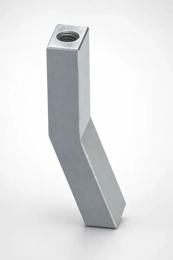
Angled Pin vs Angled Cam Comparison
While angled pins are standard for most side actions, angled cams provide the heavy-duty rigidity needed for large-area undercuts and heavy slides.
| Dimension | Angled Pins | Angled Cams |
|---|---|---|
| Motion Profile | Linear actuation via cylindrical pin. | Broad surface sliding via block cam. |
| Force Capacity | Low to Medium. Prone to bending if overloaded. | High. Distributes load over a large area. |
| Max Recommended Angle | 20 degrees (25 degrees max in extreme cases). | Up to 30 degrees safely. |
| Space Envelope | Compact. Requires a simple bored hole in the slide. | Bulky. Requires substantial machining in both mold halves. |
| Cost | Economical and easy to replace. | Higher initial cost, but robust for high-volume runs. |
| Typical Applications | Small side holes, clips, and standard slides. | Large automotive panels, heavy multi-cavity slides. |
| Maintenance | Replace pin if bent or galled. Fast turnaround. | Requires re-grinding or shim adjustments if worn. |
Component Pairing Guide
A complete side action system requires the angled pin for actuation, a stopper for positive positioning, and a retainer to hold the slide open during part drop.
| Angled Pin Type | Required Stopper Plate | Retainer | Bushing |
|---|---|---|---|
| Standard Straight Pin | Hardened Stopper Plate | Spring Plunger / Ball Catch | Bronze or Oilless Bushing |
| Flanged Angled Pin | Adjustable Stopper Block | Locking Cylinder | SKS3 Hardened Bushing |
| Heavy Duty Cam | Integrated Wedge Block | Hydraulic Core Pull (Optional) | Wear Plate (Oilless) |
Angular Pin Kinematics
Understanding the relationship between mold opening stroke and slide travel is critical to ensuring the undercut clears before part ejection.
Stroke Calculation
The lateral movement of the slide core is a direct function of the mold opening stroke and the pin's angle. The formula is S = L × tan(α), where S is the undercut stroke, L is the vertical mold opening distance, and α is the pin angle.
- Ensure the mold opens enough (L) to provide the required undercut clearance (S).
- Add a safety margin of 2-3mm to S to guarantee the slide fully clears the molded part.
- Verify that the pin does not completely exit the slide during max opening, or use extended guide rails.
Force Decomposition
As the pin angle increases, the extraction force (lateral) increases, but the vertical force acting to bend the pin also increases exponentially. The bending moment can cause premature pin failure or galling in the pin hole.
- Extraction force is related to the part's shrinkage around the core.
- Higher angles (greater than 20°) significantly increase friction and bending stresses.
- Use larger diameter pins or cams for high-extraction-force applications.
Angle Selection Guide
Selecting the correct angle balances the need for stroke within a given mold opening distance against the mechanical limits of the pin.
- 15°: Ideal for shallow undercuts. Minimal bending stress, highest longevity.
- 20°: Standard angle for most general-purpose slide cores. Excellent balance of stroke and force.
- 25°: Maximum practical angle for standard pins. Prone to wear; use only when space is severely constrained.
Frequently Asked Questions
How is the stroke of an angled pin calculated?+
What is the maximum recommended angle for an angled pin?+
Why use an angled cam instead of a simple angled pin?+
Need a Custom Quote?
Send your specifications and receive a quote. MOQ: 1 piece. Custom dimensions available.