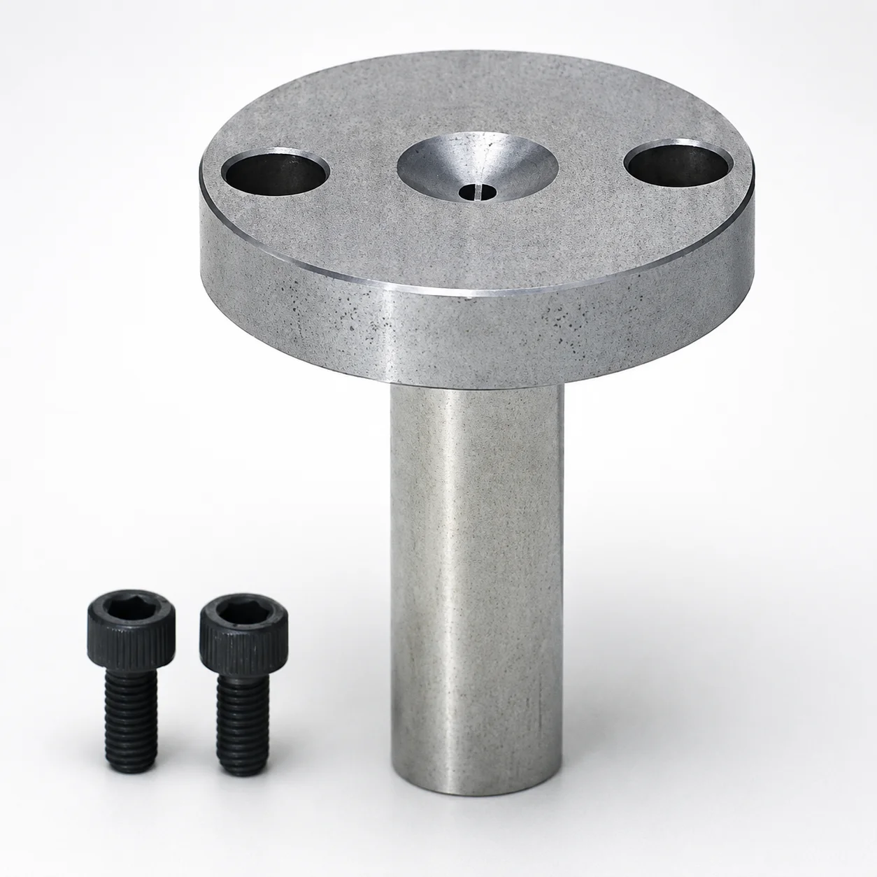
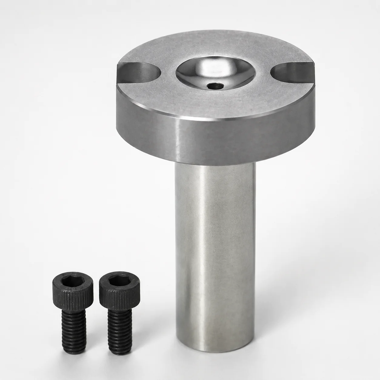
Old JIS A Type Sprue Bushings - Bolt Fixing, Flange Thickness 10 mm
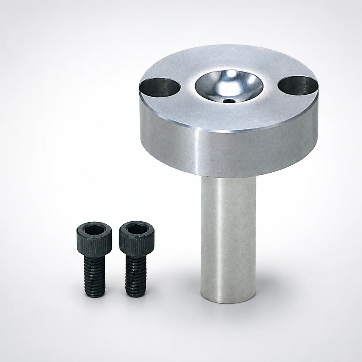
Old JIS A Type sprue bushings (bolt fixing) with 10 mm flange thickness are designed to secure the sprue system and stabilize nozzle positioning for repeatable molding. The bush mounting helps maintain reliable alignment through production cycles.
- Bolt fixing style for firm attachment and stable sprue-to-nozzle alignment
- Manufactured from S45C steel (optional equivalents available) for robust wear resistance
- Supports straight or tapered tip matching for controlled sprue interface fit
- Built for Old JIS A type molding setups, compatible with common sprue bushing assemblies
Specifications
94 configurations available
| Material | Tip Matching Shape | Nozzle Touch Part Specification | D (Shaft Diameter) (mm) | L (Bearing bore length) (mm) | A (Taper angle at sprue) (°) | F (Resin pocket depth) (mm) | G (Taper angle) (°) | P (Sprue diameter) (mm) | SR (Nozzle part) (mm) | V (Tip diameter) (mm) | type |
|---|---|---|---|---|---|---|---|---|---|---|---|
| S45C | Straight | Normal | 10 | 0 ~ 120 | 1 ~ 4 | - | - | 2 ~ 5 | 0 ~ 13 | - | - |
| S45C | Straight | Normal | 12 | 0 ~ 150 | 1 ~ 4 | - | - | 2 ~ 5 | 0 ~ 13 | - | - |
| S45C | Straight | Normal | 13 | 0 ~ 150 | 1 ~ 4 | - | - | 2 ~ 5 | 0 ~ 13 | - | - |
| S45C | Straight | Normal | 16 | 0 ~ 150 | 1 ~ 4 | - | - | 2 ~ 5 | 0 ~ 16 | - | - |
| S45C | Straight | Normal | 20 | 0 ~ 200 | 1 ~ 4 | - | - | 2 ~ 5 | 0 ~ 16 | - | - |
| S45C | Straight | Resin pocket | 10 | 0 ~ 120 | 1 ~ 4 | 0.3 ~ 2 | - | 2 ~ 5 | 10.5 ~ 11 | - | - |
| S45C | Straight | Resin pocket | 12 | 0 ~ 150 | 1 ~ 4 | 0.3 ~ 2 | - | 2 ~ 5 | 10.5 ~ 11 | - | - |
| S45C | Straight | Resin pocket | 13 | 0 ~ 150 | 1 ~ 4 | 0.3 ~ 2 | - | 2 ~ 5 | 10.5 ~ 11 | - | - |
| S45C | Straight | Resin pocket | 16 | 0 ~ 150 | 1 ~ 4 | 0.3 ~ 2 | - | 2 ~ 5 | 10.5 ~ 11 | - | - |
| S45C | Straight | Resin pocket | 20 | 0 ~ 200 | 1 ~ 4 | 0.3 ~ 2 | - | 2 ~ 5 | 10.5 ~ 11 | - | - |
| S45C | Straight | String eliminator | 10 | 0 ~ 120 | 1 ~ 4 | - | - | 2.5 ~ 5 | 0 ~ 13 | - | - |
| S45C | Straight | String eliminator | 12 | 0 ~ 150 | 1 ~ 4 | - | - | 2.5 ~ 5 | 0 ~ 13 | - | - |
| S45C | Straight | String eliminator | 13 | 0 ~ 150 | 1 ~ 4 | - | - | 2.5 ~ 5 | 0 ~ 13 | - | - |
| S45C | Straight | String eliminator | 16 | 0 ~ 150 | 1 ~ 4 | - | - | 2.5 ~ 5 | 0 ~ 16 | - | - |
| S45C | Straight | String eliminator | 20 | 0 ~ 200 | 1 ~ 4 | - | - | 2.5 ~ 5 | 0 ~ 16 | - | - |
| SKD61 | Straight | Normal | 8 | 0 ~ 80 | 1 ~ 3 | - | - | 2 ~ 3.5 | 0 ~ 11 | - | - |
| SKD61 | Straight | Normal | 10 | 0 ~ 120 | 1 ~ 4 | - | - | 2 ~ 5 | 0 ~ 13 | - | - |
| SKD61 | Straight | Normal | 12 | 0 ~ 150 | 1 ~ 4 | - | - | 2 ~ 5 | 0 ~ 13 | - | - |
| SKD61 | Straight | Normal | 13 | 0 ~ 150 | 1 ~ 4 | - | - | 2 ~ 5 | 0 ~ 13 | - | - |
| SKD61 | Straight | Normal | 16 | 0 ~ 150 | 1 ~ 4 | - | - | 2 ~ 5 | 0 ~ 16 | - | - |
| SKD61 | Straight | Normal | 20 | 0 ~ 200 | 1 ~ 4 | - | - | 2 ~ 5 | 0 ~ 16 | - | - |
| SKD61 | Straight | Resin pocket | 8 | 0 ~ 80 | 1 ~ 3 | 0.3 ~ 2 | - | 2 ~ 3.5 | 10.5 ~ 11 | - | - |
| SKD61 | Straight | Resin pocket | 10 | 0 ~ 120 | 1 ~ 4 | 0.3 ~ 2 | - | 2 ~ 5 | 10.5 ~ 11 | - | - |
| SKD61 | Straight | Resin pocket | 12 | 0 ~ 150 | 1 ~ 4 | 0.3 ~ 2 | - | 2 ~ 5 | 10.5 ~ 11 | - | - |
| SKD61 | Straight | Resin pocket | 13 | 0 ~ 150 | 1 ~ 4 | 0.3 ~ 2 | - | 2 ~ 5 | 10.5 ~ 11 | - | - |
| SKD61 | Straight | Resin pocket | 16 | 0 ~ 150 | 1 ~ 4 | 0.3 ~ 2 | - | 2 ~ 5 | 10.5 ~ 11 | - | - |
| SKD61 | Straight | Resin pocket | 20 | 0 ~ 200 | 1 ~ 4 | 0.3 ~ 2 | - | 2 ~ 5 | 10.5 ~ 11 | - | - |
| SKD61 | Straight | String eliminator | 10 | 0 ~ 120 | 1 ~ 4 | - | - | 2.5 ~ 5 | 0 ~ 13 | - | - |
| SKD61 | Straight | String eliminator | 12 | 0 ~ 150 | 1 ~ 4 | - | - | 2.5 ~ 5 | 0 ~ 13 | - | - |
| SKD61 | Straight | String eliminator | 13 | 0 ~ 150 | 1 ~ 4 | - | - | 2.5 ~ 5 | 0 ~ 13 | - | - |
| SKD61 | Straight | String eliminator | 16 | 0 ~ 150 | 1 ~ 4 | - | - | 2.5 ~ 5 | 0 ~ 16 | - | - |
| SKD61 | Straight | String eliminator | 20 | 0 ~ 200 | 1 ~ 4 | - | - | 2.5 ~ 5 | 0 ~ 16 | - | - |
| HPM1 Equivalent | Straight | Normal | 8 | 0 ~ 80 | 1 ~ 3 | - | - | 2 ~ 3.5 | 0 ~ 11 | - | - |
| HPM1 Equivalent | Straight | Normal | 10 | 0 ~ 120 | 1 ~ 4 | - | - | 2 ~ 5 | 0 ~ 13 | - | - |
| HPM1 Equivalent | Straight | Normal | 12 | 0 ~ 150 | 1 ~ 4 | - | - | 2 ~ 5 | 0 ~ 13 | - | - |
| HPM1 Equivalent | Straight | Normal | 13 | 0 ~ 150 | 1 ~ 4 | - | - | 2 ~ 5 | 0 ~ 13 | - | - |
| HPM1 Equivalent | Straight | Normal | 16 | 0 ~ 150 | 1 ~ 4 | - | - | 2 ~ 5 | 0 ~ 16 | - | - |
| HPM1 Equivalent | Straight | Normal | 20 | 0 ~ 200 | 1 ~ 4 | - | - | 2 ~ 5 | 0 ~ 16 | - | - |
| HPM1 Equivalent | Straight | Resin pocket | 8 | 0 ~ 80 | 1 ~ 3 | 0.3 ~ 2 | - | 2 ~ 3.5 | 10.5 ~ 11 | - | - |
| HPM1 Equivalent | Straight | Resin pocket | 10 | 0 ~ 120 | 1 ~ 4 | 0.3 ~ 2 | - | 2 ~ 5 | 10.5 ~ 11 | - | - |
| HPM1 Equivalent | Straight | Resin pocket | 12 | 0 ~ 150 | 1 ~ 4 | 0.3 ~ 2 | - | 2 ~ 5 | 10.5 ~ 11 | - | - |
| HPM1 Equivalent | Straight | Resin pocket | 13 | 0 ~ 150 | 1 ~ 4 | 0.3 ~ 2 | - | 2 ~ 5 | 10.5 ~ 11 | - | - |
| HPM1 Equivalent | Straight | Resin pocket | 16 | 0 ~ 150 | 1 ~ 4 | 0.3 ~ 2 | - | 2 ~ 5 | 10.5 ~ 11 | - | - |
| HPM1 Equivalent | Straight | Resin pocket | 20 | 0 ~ 200 | 1 ~ 4 | 0.3 ~ 2 | - | 2 ~ 5 | 10.5 ~ 11 | - | - |
| HPM1 Equivalent | Straight | String eliminator | 10 | 0 ~ 120 | 1 ~ 4 | - | - | 2.5 ~ 5 | 0 ~ 13 | - | - |
| HPM1 Equivalent | Straight | String eliminator | 12 | 0 ~ 150 | 1 ~ 4 | - | - | 2.5 ~ 5 | 0 ~ 13 | - | - |
| HPM1 Equivalent | Straight | String eliminator | 13 | 0 ~ 150 | 1 ~ 4 | - | - | 2.5 ~ 5 | 0 ~ 13 | - | - |
| HPM1 Equivalent | Straight | String eliminator | 16 | 0 ~ 150 | 1 ~ 4 | - | - | 2.5 ~ 5 | 0 ~ 16 | - | - |
| HPM1 Equivalent | Straight | String eliminator | 20 | 0 ~ 200 | 1 ~ 4 | - | - | 2.5 ~ 5 | 0 ~ 16 | - | - |
| S45C | Tapered | Normal | 10 | 0 ~ 120 | 1 ~ 4 | - | 1 ~ 10 | 2 ~ 5 | 0 ~ 13 | 4 ~ 13 | - |
Product Guide
Application Scenarios+
Sprue bushings like this bolt-fixing Old JIS A type variant are used to lock the sprue system to the nozzle interface in conventional injection mold tooling. The 10 mm flange thickness supports consistent stack-up and nozzle seating, helping maintain repeatable alignment during long production runs.
- Automotive connector and housing molds: Ideal when stable sprue-to-nozzle positioning is required to reduce misalignment-related flow disturbances. The bolt fixing style provides rigid attachment for controlled resin feed.
- Consumer electronics enclosure molds: Compatible with common Old JIS A type sprue bushing setups where straight or tapered tip matching is used to maintain a consistent sprue interface fit.
- Medical/precision parts with interface control: Select the nozzle touch part options (normal, resin pocket, or string eliminator) to tune gate/shear behavior and manage stringing at the nozzle contact region.
Choose appropriate tip matching (straight vs. tapered) and nozzle touch part specification to match the required sprue interface geometry and flow control needs.
Material & Process Details+
This sprue bushing series is available in S45C, SKD61, or HPM1 (equivalent), allowing selection based on the thermal and wear demands of the molding cycle.
- S45C: A medium-carbon steel typically used in a quenched & tempered condition for balanced strength and wear resistance. It offers good toughness, but wear resistance is generally lower than higher-alloy tool steels.
- SKD61 (H13 equivalent): commonly supplied in a heat-treated tool-steel state (quenched & tempered) to improve hot hardness and toughness for durability under repeated thermal cycling.
- HPM1 (equivalent): selected where extended wear life and stable performance are needed at gate/nozzle contact regions.
Hardness note: The exact HRC for each option is not specified in the provided data, so confirm the supplied condition for your supplier’s machining tolerance and expected abrasion resistance. In practice, alloy tool steels improve wear resistance while slightly reducing toughness margin compared with S45C.
Sizing & Selection Guide+
To select the correct sprue bushing, match both the shaft diameter D and the bearing bore length L to your mold’s sprue/nozzle alignment stack-up for the Old JIS A type interface.
- Shaft diameter D (mm): choose from 8, 10, 12, 13, 16, 20 to fit the mating bore or recess in the nozzle seat area.
- Bearing bore length L (mm): ranges depend on the selected D, including 0–120, 0–150, 0–200, 0–80, or 0–150 (as listed per configuration). Select L so the bushing fully supports the bearing region without over-penetration.
- Sprue diameter P (mm): choose from 2–5, 2.5–5, or 2–3.5 to align with your sprue/gate opening requirement.
- Tip geometry: pick Tip matching shape (Straight or Tapered) and confirm V (tip diameter) (mm) and taper angles A (1–4° or 1–3°) / G (1–10°).
Tolerance/fit: Ensure your nozzle contact spec (Normal, Resin pocket, or String eliminator) and the selected tip diameter range (V) match the corresponding nozzle touch part geometry to maintain a stable seal and prevent resin flashing or air entrapment.
Frequently Asked Questions
Which tip matching shape (Straight vs Tapered) should be selected for an Old JIS A type nozzle interface?+
Select Straight tip matching when your nozzle sprue contact requires a uniform diameter interface. Choose Tapered when the nozzle/sprue interface uses an angle profile and you need controlled seating. Then confirm the V (tip diameter) range and the taper angles A (1–4° or 1–3°) and G (1–10°) to maintain fit.
How do I choose the correct bearing bore length L for this bolt-fixing sprue bushing?+
Use the provided L (bearing bore length) ranges tied to the selected D. The data lists options such as 0–120, 0–150, 0–200, 0–80, and 0–150 depending on configuration. Select L so the bushing supports the bearing region fully while avoiding interference with adjacent sprue components and maintaining the intended nozzle seating position for bolt-fixed stack-up.
What nozzle touch part specification options are available, and when should I use Resin pocket or String eliminator?+
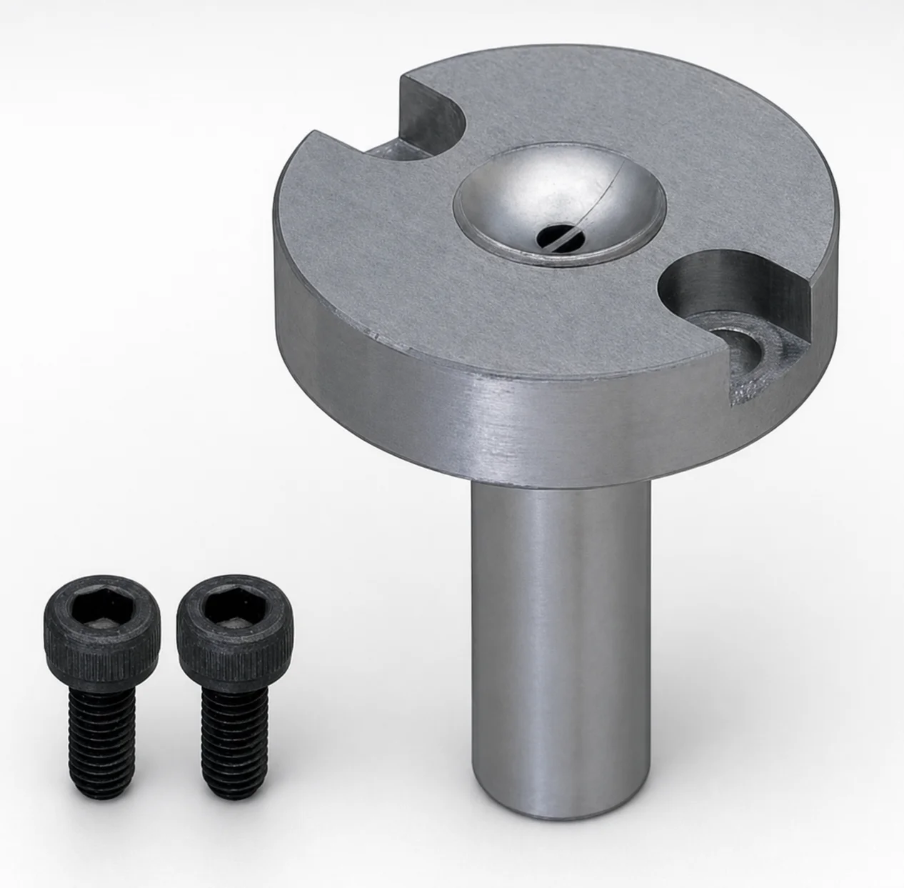
The nozzle touch part specification can be set to Normal, Resin pocket, or String eliminator. Use Resin pocket when you need controlled resin retention at the nozzle interface region. Choose String eliminator for applications where stringing reduction at the nozzle contact is a priority.
How do I match sprue diameter P and tip diameter V to prevent flow mismatch at the sprue/nozzle contact?+
Match P (sprue diameter) from 2–5, 2.5–5, or 2–3.5 mm to the required sprue opening. Then select the appropriate V (tip diameter) range (e.g., 4–13, 4–16, 4–20, 4.8–12.9, 4.8–15.9, or 4.8–19.9 mm) according to the nozzle touch design. Consistent P/V matching helps maintain stable interface flow and reduces flashing or air gaps.
Which material option is best suited for wear resistance: S45C, SKD61 (H13 equivalent), or HPM1 equivalent?+
Your choice depends on cycle durability requirements. S45C is suitable for balanced strength but typically offers lower wear resistance than tool steels. SKD61 (H13 equivalent) is selected for improved hot hardness and longer life under repeated thermal cycling. HPM1 equivalent is also offered for extended wear performance at the nozzle-contact region.
Related Products
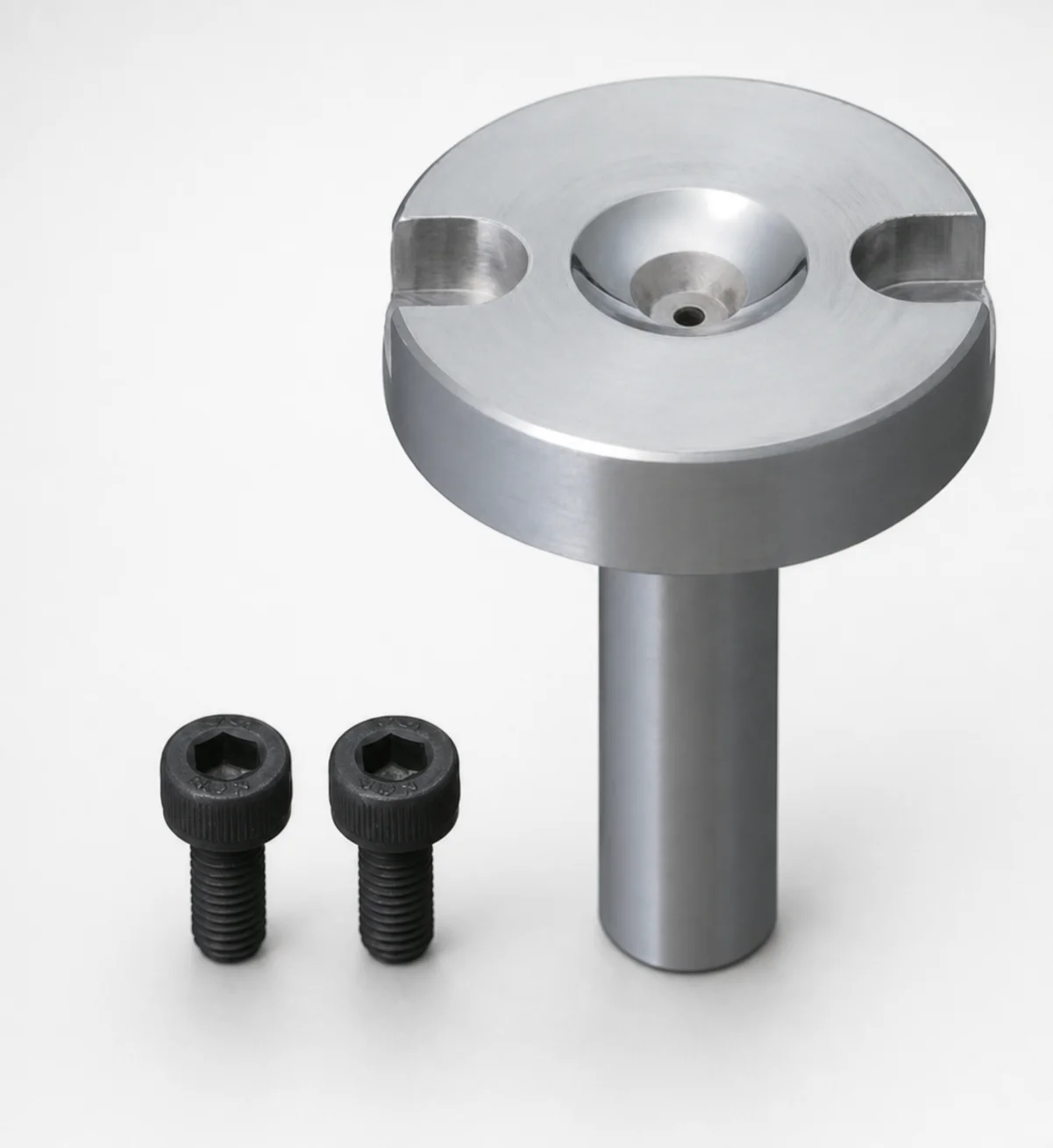
Bolt Fixing Sprue Bushings - Flange Thickness 10 mm
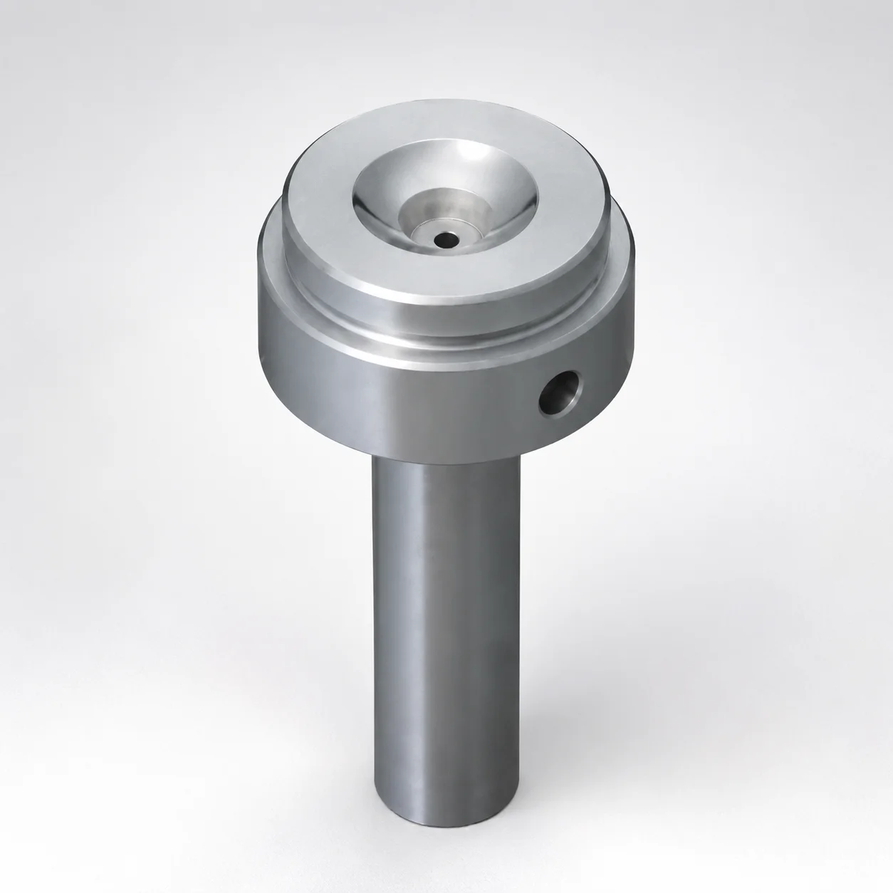
Sprue Bushings Shoulder Type - Flange Thickness 15 mm
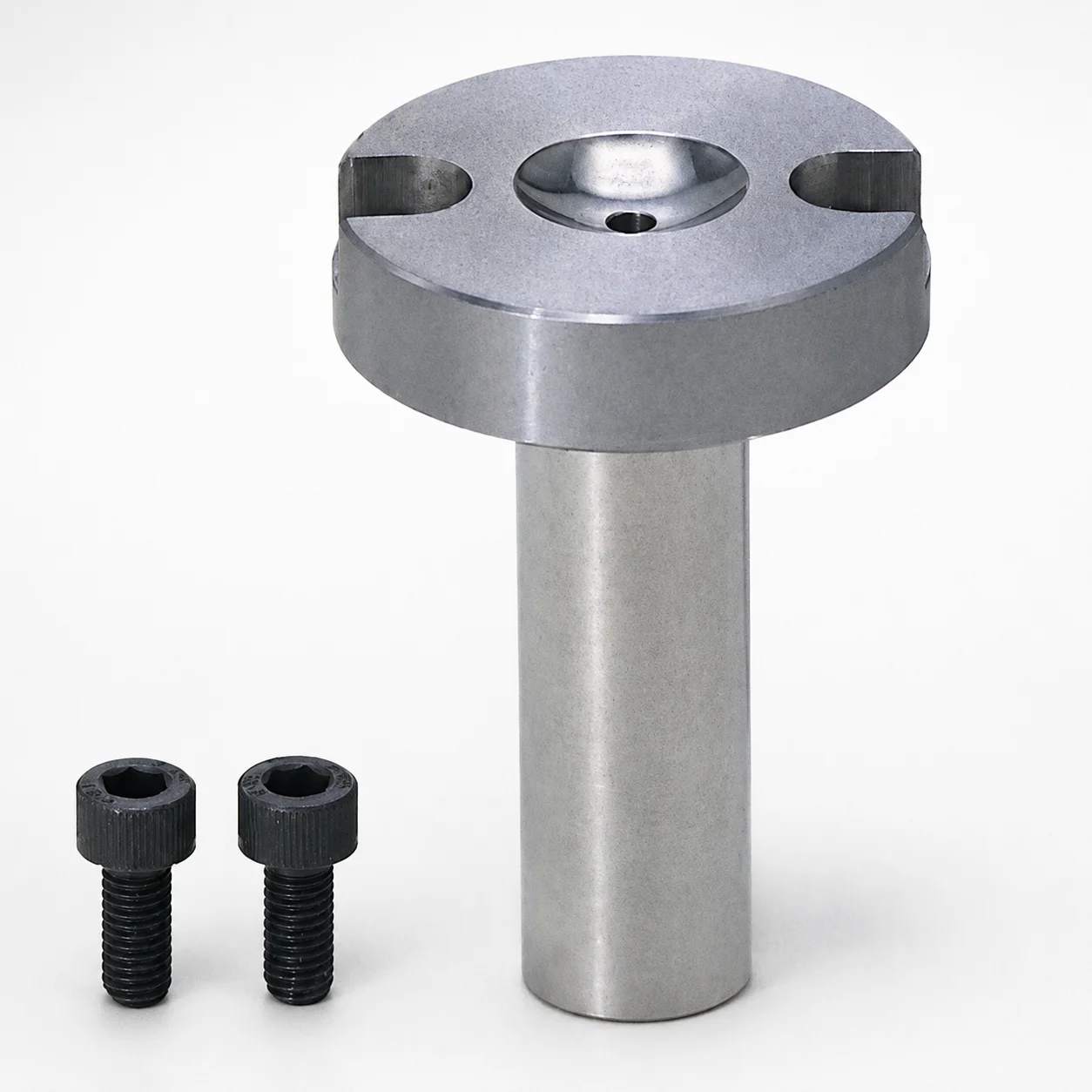
Sprue Bushings - Bolt Fixing Flange Thickness 10 mm
Sprue Bushings - Bolt Fixing, Flange Thickness 10 mm
JIS Standard Steel Sprue Bushings - Bolt Fixing String Eliminator (Flange 10 mm)
Sprue Bushings - Bolt Fixing Flange Thickness 15 mm
Need Custom Specifications?
Our engineering team can help with custom configurations, material selection, and volume pricing.