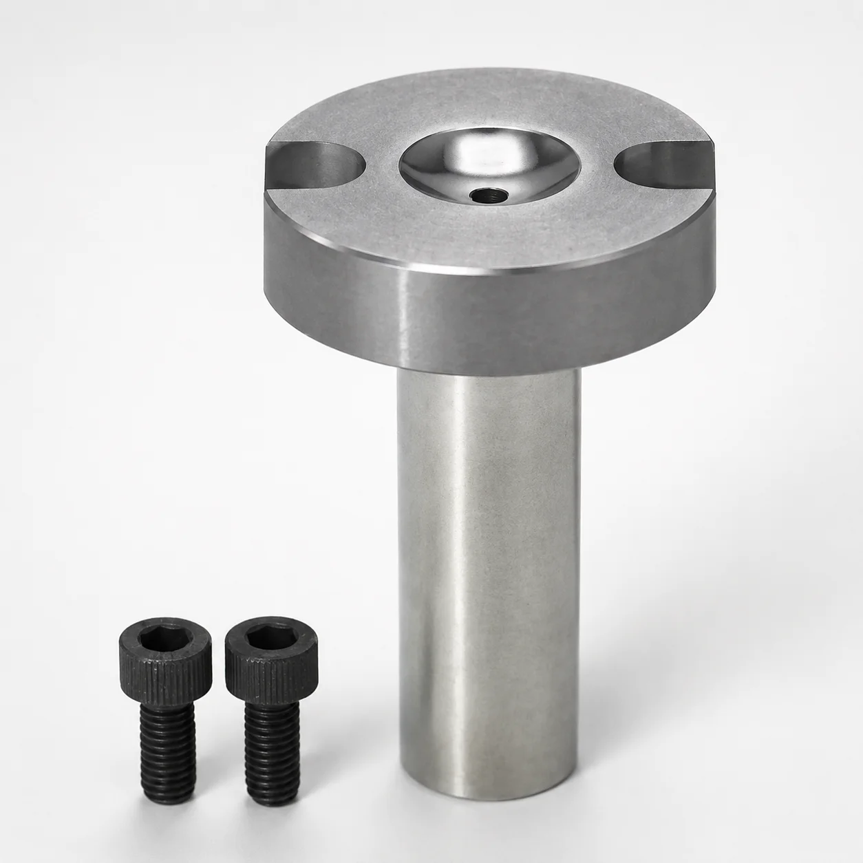
Sprue Bushings - Bolt Fixing, Flange Thickness 10 mm
Sprue Bushings - Bolt Fixing, Flange Thickness 10 mm are designed to secure the nozzle connection using bolt fixing and a 10 mm flange interface. Choose the suitable tip matching and material grade for consistent assembly performance.
- Bolt fixing style with 10 mm flange thickness for stable mounting
- Multiple steel options including SKD61 and DC53 to support durable service
- Tip matching options such as straight and tapered for proper nozzle mating
- Made for sprue/nozzle related mold hardware to streamline setup
Specifications
58 configurations available
| Material | Tip Matching Shape | Nozzle Touch Part Specification | D (Shaft Diameter) (mm) | L (Bearing bore length) (mm) | A (Taper angle at sprue) (°) | G (Taper angle) (°) | P (Sprue diameter) (mm) | SR (Nozzle part) (mm) | V (Tip diameter) (mm) | type |
|---|---|---|---|---|---|---|---|---|---|---|
| SKD61 | Straight | Normal | 8 | 0 ~ 80 | 0.5 ~ 3 | - | 2 ~ 3.5 | 0 ~ 11 | - | - |
| SKD61 | Straight | Normal | 10 | 0 ~ 120 | 0.5 ~ 4 | - | 2 ~ 8 | 0 ~ 20 | - | - |
| SKD61 | Straight | Normal | 12 | 0 ~ 150 | 0.5 ~ 4 | - | 2 ~ 8 | 0 ~ 20 | - | - |
| SKD61 | Straight | Normal | 13 | 0 ~ 150 | 0.5 ~ 4 | - | 2 ~ 8 | 0 ~ 20 | - | - |
| SKD61 | Straight | Normal | 16 | 0 ~ 150 | 0.5 ~ 4 | - | 2 ~ 8 | 0 ~ 20 | - | - |
| SKD61 | Straight | Normal | 20 | 0 ~ 200 | 0.5 ~ 4 | - | 2 ~ 8 | 0 ~ 20 | - | - |
| SKD61 | Straight | String eliminator | 10 | 0 ~ 120 | 0.5 ~ 4 | - | 2.5 ~ 8 | 0 ~ 16 | - | - |
| SKD61 | Straight | String eliminator | 12 | 0 ~ 150 | 0.5 ~ 4 | - | 2.5 ~ 8 | 0 ~ 16 | - | - |
| SKD61 | Straight | String eliminator | 13 | 0 ~ 150 | 0.5 ~ 4 | - | 2.5 ~ 8 | 0 ~ 16 | - | - |
| SKD61 | Straight | String eliminator | 16 | 0 ~ 150 | 0.5 ~ 4 | - | 2.5 ~ 8 | 0 ~ 16 | - | - |
| SKD61 | Straight | String eliminator | 20 | 0 ~ 200 | 0.5 ~ 4 | - | 2.5 ~ 8 | 0 ~ 16 | - | - |
| HPM1 Equivalent | Straight | Normal | 8 | 0 ~ 80 | 0.5 ~ 3 | - | 2 ~ 3.5 | 0 ~ 11 | - | - |
| HPM1 Equivalent | Straight | Normal | 10 | 0 ~ 120 | 0.5 ~ 4 | - | 2 ~ 8 | 0 ~ 20 | - | - |
| HPM1 Equivalent | Straight | Normal | 12 | 0 ~ 150 | 0.5 ~ 4 | - | 2 ~ 8 | 0 ~ 20 | - | - |
| HPM1 Equivalent | Straight | Normal | 13 | 0 ~ 150 | 0.5 ~ 4 | - | 2 ~ 8 | 0 ~ 20 | - | - |
| HPM1 Equivalent | Straight | Normal | 16 | 0 ~ 150 | 0.5 ~ 4 | - | 2 ~ 8 | 0 ~ 20 | - | - |
| HPM1 Equivalent | Straight | Normal | 20 | 0 ~ 200 | 0.5 ~ 4 | - | 2 ~ 8 | 0 ~ 20 | - | - |
| HPM1 Equivalent | Straight | String eliminator | 10 | 0 ~ 120 | 0.5 ~ 4 | - | 2.5 ~ 8 | 0 ~ 16 | - | - |
| HPM1 Equivalent | Straight | String eliminator | 12 | 0 ~ 150 | 0.5 ~ 4 | - | 2.5 ~ 8 | 0 ~ 16 | - | - |
| HPM1 Equivalent | Straight | String eliminator | 13 | 0 ~ 150 | 0.5 ~ 4 | - | 2.5 ~ 8 | 0 ~ 16 | - | - |
| HPM1 Equivalent | Straight | String eliminator | 16 | 0 ~ 150 | 0.5 ~ 4 | - | 2.5 ~ 8 | 0 ~ 16 | - | - |
| HPM1 Equivalent | Straight | String eliminator | 20 | 0 ~ 200 | 0.5 ~ 4 | - | 2.5 ~ 8 | 0 ~ 16 | - | - |
| DC53 | Straight | Normal | 10 | 0 ~ 100 | 0.5 ~ 4 | - | 2 ~ 8 | 0 ~ 20 | - | - |
| DC53 | Straight | Normal | 12 | 0 ~ 100 | 0.5 ~ 4 | - | 2 ~ 8 | 0 ~ 20 | - | - |
| DC53 | Straight | Normal | 13 | 0 ~ 100 | 0.5 ~ 4 | - | 2 ~ 8 | 0 ~ 20 | - | - |
| DC53 | Straight | Normal | 16 | 0 ~ 100 | 0.5 ~ 4 | - | 2 ~ 8 | 0 ~ 20 | - | - |
| DC53 | Straight | String eliminator | 10 | 0 ~ 100 | 0.5 ~ 4 | - | 2.5 ~ 8 | 0 ~ 16 | - | - |
| DC53 | Straight | String eliminator | 12 | 0 ~ 100 | 0.5 ~ 4 | - | 2.5 ~ 8 | 0 ~ 16 | - | - |
| DC53 | Straight | String eliminator | 13 | 0 ~ 100 | 0.5 ~ 4 | - | 2.5 ~ 8 | 0 ~ 16 | - | - |
| DC53 | Straight | String eliminator | 16 | 0 ~ 100 | 0.5 ~ 4 | - | 2.5 ~ 8 | 0 ~ 16 | - | - |
| SKD61 | Tapered | Normal | 10 | 0 ~ 120 | 0.5 ~ 4 | 1 ~ 10 | 2 ~ 8 | 0 ~ 20 | 4 ~ 10 | - |
| SKD61 | Tapered | Normal | 12 | 0 ~ 150 | 0.5 ~ 4 | 1 ~ 10 | 2 ~ 8 | 0 ~ 20 | 4 ~ 13 | - |
| SKD61 | Tapered | Normal | 13 | 0 ~ 150 | 0.5 ~ 4 | 1 ~ 10 | 2 ~ 8 | 0 ~ 20 | 4 ~ 13 | - |
| SKD61 | Tapered | Normal | 16 | 0 ~ 150 | 0.5 ~ 4 | 1 ~ 10 | 2 ~ 8 | 0 ~ 20 | 4 ~ 16 | - |
| SKD61 | Tapered | Normal | 20 | 0 ~ 200 | 0.5 ~ 4 | 1 ~ 10 | 2 ~ 8 | 0 ~ 20 | 4 ~ 20 | - |
| SKD61 | Tapered | String eliminator | 10 | 0 ~ 120 | 0.5 ~ 4 | 1 ~ 10 | 2.5 ~ 8 | 0 ~ 16 | 4.8 ~ 9.9 | - |
| SKD61 | Tapered | String eliminator | 12 | 0 ~ 150 | 0.5 ~ 4 | 1 ~ 10 | 2.5 ~ 8 | 0 ~ 16 | 4.8 ~ 12.9 | - |
| SKD61 | Tapered | String eliminator | 13 | 0 ~ 150 | 0.5 ~ 4 | 1 ~ 10 | 2.5 ~ 8 | 0 ~ 16 | 4.8 ~ 12.9 | - |
| SKD61 | Tapered | String eliminator | 16 | 0 ~ 150 | 0.5 ~ 4 | 1 ~ 10 | 2.5 ~ 8 | 0 ~ 16 | 4.8 ~ 15.9 | - |
| SKD61 | Tapered | String eliminator | 20 | 0 ~ 200 | 0.5 ~ 4 | 1 ~ 10 | 2.5 ~ 8 | 0 ~ 16 | 4.8 ~ 19.9 | - |
| HPM1 Equivalent | Tapered | Normal | 10 | 0 ~ 120 | 0.5 ~ 4 | 1 ~ 10 | 2 ~ 8 | 0 ~ 20 | 4 ~ 10 | - |
| HPM1 Equivalent | Tapered | Normal | 12 | 0 ~ 150 | 0.5 ~ 4 | 1 ~ 10 | 2 ~ 8 | 0 ~ 20 | 4 ~ 13 | - |
| HPM1 Equivalent | Tapered | Normal | 13 | 0 ~ 150 | 0.5 ~ 4 | 1 ~ 10 | 2 ~ 8 | 0 ~ 20 | 4 ~ 13 | - |
| HPM1 Equivalent | Tapered | Normal | 16 | 0 ~ 150 | 0.5 ~ 4 | 1 ~ 10 | 2 ~ 8 | 0 ~ 20 | 4 ~ 16 | - |
| HPM1 Equivalent | Tapered | Normal | 20 | 0 ~ 200 | 0.5 ~ 4 | 1 ~ 10 | 2 ~ 8 | 0 ~ 20 | 4 ~ 20 | - |
| HPM1 Equivalent | Tapered | String eliminator | 10 | 0 ~ 120 | 0.5 ~ 4 | 1 ~ 10 | 2.5 ~ 8 | 0 ~ 16 | 4.8 ~ 9.9 | - |
| HPM1 Equivalent | Tapered | String eliminator | 12 | 0 ~ 150 | 0.5 ~ 4 | 1 ~ 10 | 2.5 ~ 8 | 0 ~ 16 | 4.8 ~ 12.9 | - |
| HPM1 Equivalent | Tapered | String eliminator | 13 | 0 ~ 150 | 0.5 ~ 4 | 1 ~ 10 | 2.5 ~ 8 | 0 ~ 16 | 4.8 ~ 12.9 | - |
| HPM1 Equivalent | Tapered | String eliminator | 16 | 0 ~ 150 | 0.5 ~ 4 | 1 ~ 10 | 2.5 ~ 8 | 0 ~ 16 | 4.8 ~ 15.9 | - |
| HPM1 Equivalent | Tapered | String eliminator | 20 | 0 ~ 200 | 0.5 ~ 4 | 1 ~ 10 | 2.5 ~ 8 | 0 ~ 16 | 4.8 ~ 19.9 | - |
Product Guide
Application Scenarios+
This bolt-fixing sprue bushing with a 10 mm flange interface is used to lock the nozzle connection in injection mold tooling where assembly stability and repeatability matter. The flange distributes clamping load and helps maintain alignment during thermal cycling, reducing risk of leakage or mismatch at the sprue/nozzle interface.
- Automotive connector and terminal molds: Use the stable bolt-fixing layout for high-cycle production where consistent sprue quality and tight nozzle mating are required; select the straight or tapered tip match to correspond to the nozzle touch geometry.
- Industrial appliance housings: Choose the appropriate nozzle touch part specification (normal or string eliminator) to support desired flow behavior and reduce stringing near the gate.
- General sprue/nozzle hardware builds: Pick the steel grade and tip shape to match wear and assembly requirements while keeping the 10 mm flange thickness for straightforward installation on standard mold plates.
Material & Process Details+
Available steels are selected to balance wear resistance, toughness, and service life in sprue/nozzle region exposure. SKD61 is commonly treated as an H13 equivalent, suitable for durable tooling under cyclic heating; it is typically quenched & tempered to achieve stable hardness for gate-area contact.
DC53 is a mold steel option aimed at improved wear resistance, often used where surface durability at the nozzle touch area is critical. HPM1 (equivalent) is offered as an alternative grade for tool steels in this family, depending on your expected thermal/mechanical loading and machining needs.
- Hardness & performance trade-off: Higher hardness generally improves wear resistance at the nozzle contact surfaces, while slightly lower toughness can increase chipping risk under misalignment.
- Selection guidance: If your process emphasizes abrasion and long runs, consider DC53; for broad cyclic performance, SKD61/HPM1 are typical choices.
Sizing & Selection Guide+
To select the correct sprue bushing dimensions, start by matching the shaft diameter (D) to the nozzle opening/interface requirement: available D values are 8, 10, 12, 13, 16, 20 mm. Then choose the bearing bore length L from the available ranges (0–80, 0–120, 0–150, 0–200, or 0–100 mm) to fit your mold plate thickness and the required engagement depth with the nozzle.
- Taper engagement: Use the sprue taper angle A range of 0.5–3° or 0.5–4° based on your gate geometry, and keep the fixed taper angle G = 1–10° as specified for this part family.
- Sprue diameter (P): Select P = 2–3.5 mm, 2–8 mm, or 2.5–8 mm to align with the sprue diameter in the mold.
- Tip diameter (V): Confirm tip diameter V = 4 to 4.8 mm and choose nozzle touch specification (normal vs string eliminator) to match nozzle mating.
Tip matching shape (straight or tapered) is configurable, while the flange thickness is 10 mm, helping standardize installation on the mold plate.
Frequently Asked Questions
Which steel grade should I choose for sprue/nozzle contact wear in long-run production?+
For long-run wear durability in the nozzle touch region, the product is offered in DC53 or SKD61 (H13 equivalent) depending on your balance of hardness and toughness needs. If you expect frequent thermal cycling, SKD61/HPM1 are commonly selected for stable cyclic performance.
Review your expected abrasion and the risk of chipping from misalignment, then select the grade that best matches your gate-area loading.
How do I select the correct tip matching shape (straight vs tapered) for nozzle mating?+
This sprue bushing supports tip matching shape options: straight and tapered. Choose the shape that matches your nozzle geometry so the nozzle touches properly at the sprue/nozzle interface.
Then verify tip diameter V = 4–4.8 mm and the nozzle touch part specification (normal or string eliminator) to ensure correct engagement.
What sizing parameters determine compatibility with my sprue and nozzle diameters?+
Compatibility is primarily controlled by D (shaft diameter) and P (sprue diameter). Confirm D = 8, 10, 12, 13, 16, or 20 mm, then select the appropriate P range (2–3.5, 2–8, or 2.5–8 mm) based on your mold sprue dimensions.
Also confirm the nozzle touch specification and tip diameter V = 4–4.8 mm so the nozzle interfaces correctly.
How should I pick bearing bore length (L) for proper engagement depth?+
Select L from the available bearing bore length ranges: 0–80, 0–120, 0–150, 0–200, or 0–100 mm. Use L to ensure the nozzle connection has sufficient engagement depth without over-inserting into the nozzle touch zone.
Because the flange thickness is fixed at 10 mm, L primarily compensates for mold plate thickness and desired engagement geometry.
What are the sprue taper angle options (A and G), and how do they affect gate geometry?+
The variable sprue taper angle A is available in ranges 0.5–3° and 0.5–4°, while the fixed taper angle G is specified as 1–10° for this part family. Choose A to match your target sprue taper profile, and keep G within the specified range to preserve the intended interface form.
After selecting angles, verify sprue diameter P and tip matching shape to prevent mismatch at the nozzle touch area.
Related Products
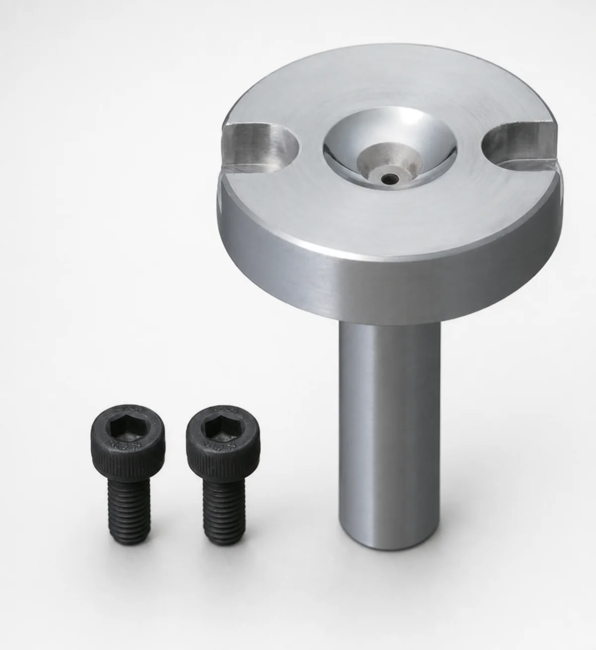
Bolt Fixing Sprue Bushings - Flange Thickness 10 mm
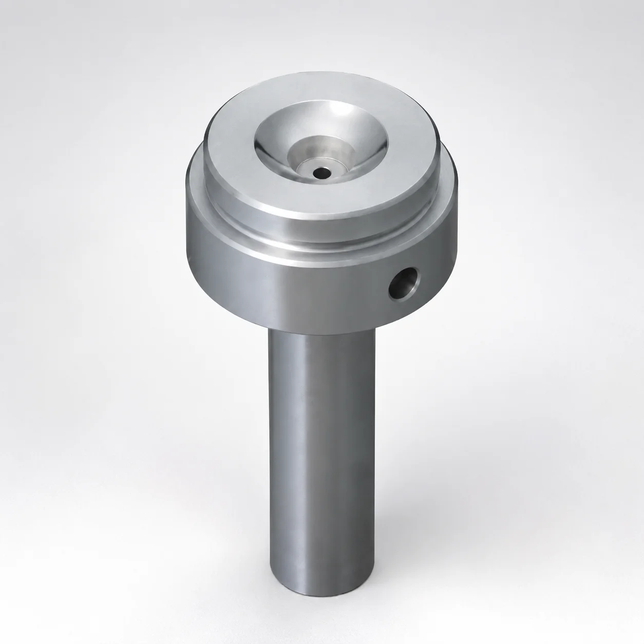
Sprue Bushings Shoulder Type - Flange Thickness 15 mm
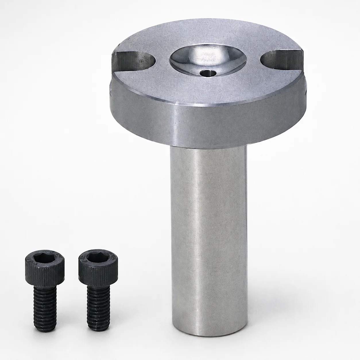
Sprue Bushings - Bolt Fixing Flange Thickness 10 mm
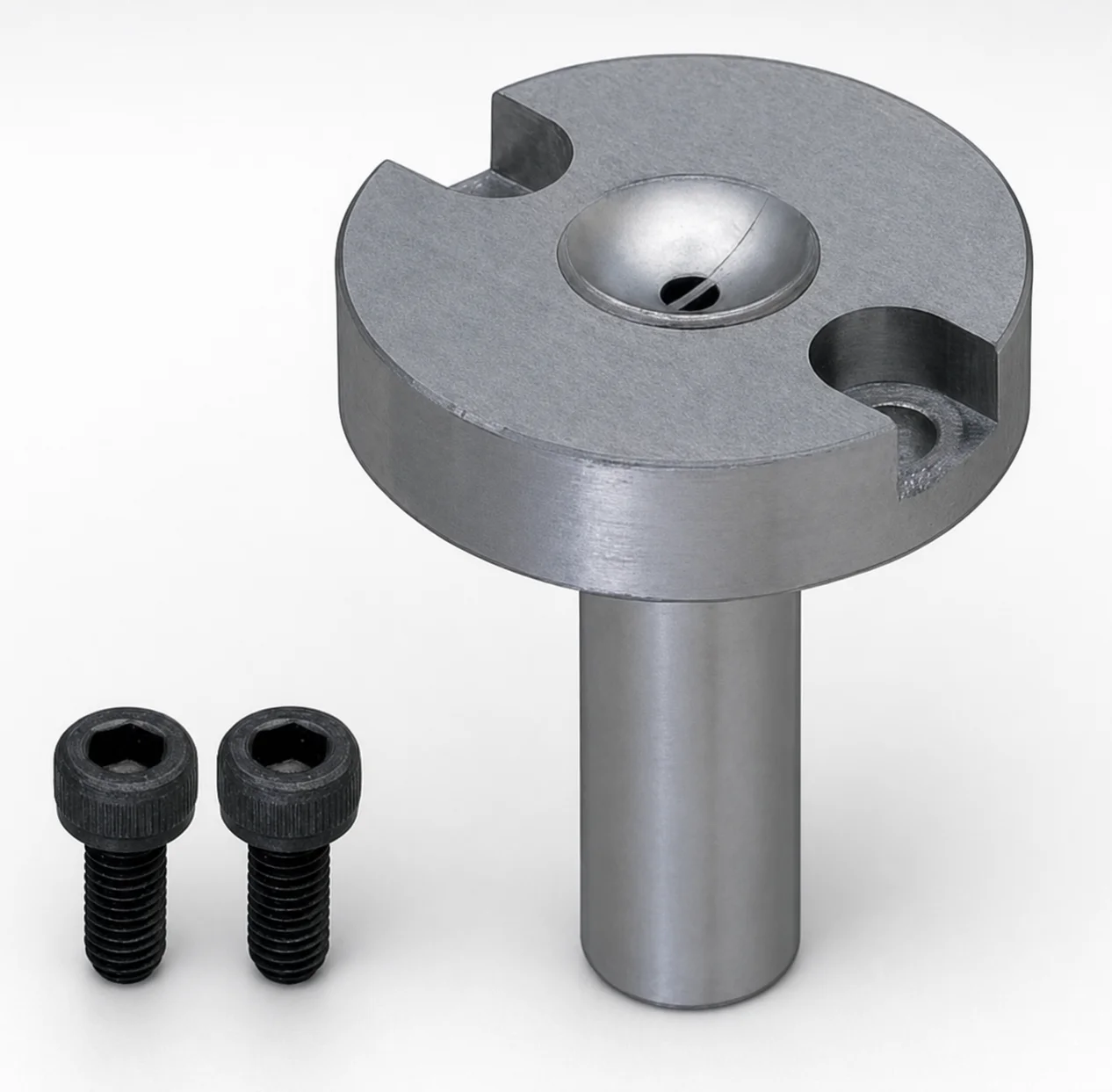
JIS Standard Steel Sprue Bushings - Bolt Fixing String Eliminator (Flange 10 mm)
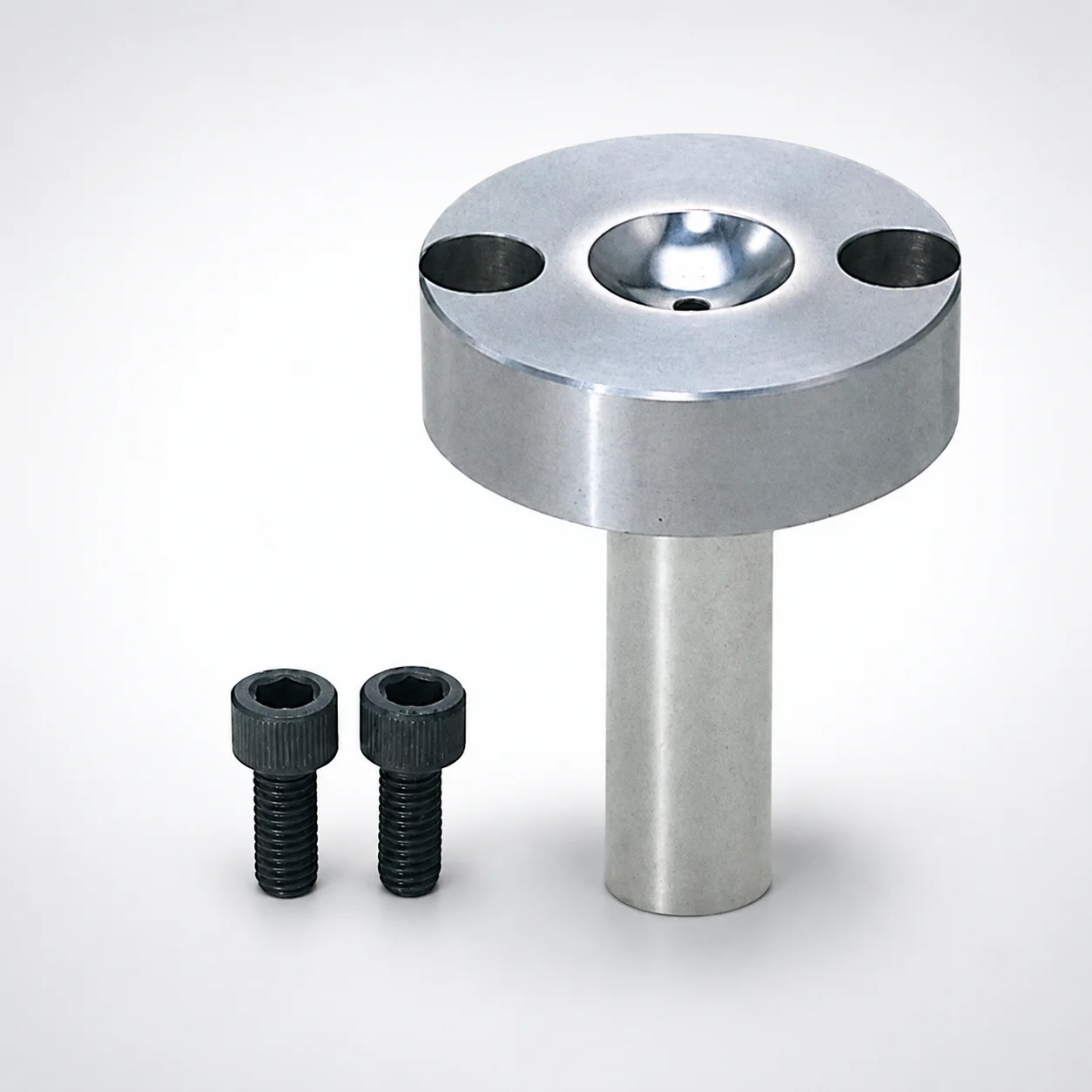
Sprue Bushings - Bolt Fixing Flange Thickness 15 mm
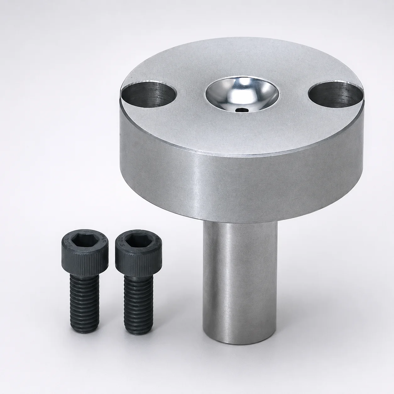
Sprue Bushings - Bolt Fixing, Flange Thickness 20 mm
Need Custom Specifications?
Our engineering team can help with custom configurations, material selection, and volume pricing.