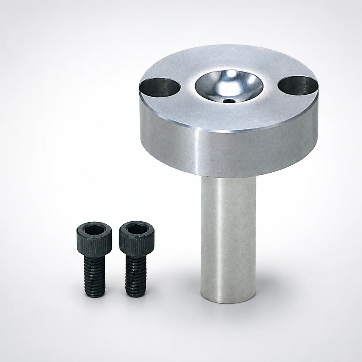
Sprue Bushings - Bolt Fixing Flange Thickness 15 mm
Sprue Bushings - Bolt Fixing Flange Thickness 15 mm are designed for rigid sprue mounting on injection molds, using a bolt-fixing configuration for stable alignment during production. They support normal nozzle touch and string eliminator arrangements to match different feed setups.
- Flange thickness 15 mm bolt-fixing design for reliable sprue positioning in the mold
- Materials available including SKD61, DC53, and HPM1 equivalent for wear-resistant performance
- Tip matching options such as straight or tapered to suit different nozzle interfaces
- Supports normal or string eliminator nozzle touch parts for controlled flow handling
Specifications
36 configurations available
| Material | Tip Matching Shape | Nozzle Touch Part Specification | D (Shaft Diameter) (mm) | L (Bearing bore length) (mm) | A (Taper angle at sprue) (°) | G (Taper angle) (°) | P (Sprue diameter) (mm) | SR (Nozzle part) (mm) | V (Tip diameter) (mm) | type |
|---|---|---|---|---|---|---|---|---|---|---|
| HPM1 Equivalent | Straight | Normal | 16 | 30 ~ 150 | 1 ~ 4 | - | 2 ~ 8 | 0 ~ 23 | - | - |
| HPM1 Equivalent | Straight | Normal | 20 | 30 ~ 200 | 1 ~ 4 | - | 2 ~ 8 | 0 ~ 23 | - | - |
| HPM1 Equivalent | Straight | Normal | 25 | 30 ~ 200 | 1 ~ 4 | - | 2 ~ 8 | 0 ~ 23 | - | - |
| HPM1 Equivalent | Straight | String eliminator | 16 | 30 ~ 150 | 1 ~ 4 | - | 2.5 ~ 8 | 0 ~ 23 | - | - |
| HPM1 Equivalent | Straight | String eliminator | 20 | 30 ~ 200 | 1 ~ 4 | - | 2.5 ~ 8 | 0 ~ 23 | - | - |
| HPM1 Equivalent | Straight | String eliminator | 25 | 30 ~ 200 | 1 ~ 4 | - | 2.5 ~ 8 | 0 ~ 23 | - | - |
| SKD61 | Straight | Normal | 16 | 30 ~ 150 | 1 ~ 4 | - | 2 ~ 8 | 0 ~ 23 | - | - |
| SKD61 | Straight | Normal | 20 | 30 ~ 200 | 1 ~ 4 | - | 2 ~ 8 | 0 ~ 23 | - | - |
| SKD61 | Straight | Normal | 25 | 30 ~ 200 | 1 ~ 4 | - | 2 ~ 8 | 0 ~ 23 | - | - |
| SKD61 | Straight | String eliminator | 16 | 30 ~ 150 | 1 ~ 4 | - | 2.5 ~ 8 | 0 ~ 23 | - | - |
| SKD61 | Straight | String eliminator | 20 | 30 ~ 200 | 1 ~ 4 | - | 2.5 ~ 8 | 0 ~ 23 | - | - |
| SKD61 | Straight | String eliminator | 25 | 30 ~ 200 | 1 ~ 4 | - | 2.5 ~ 8 | 0 ~ 23 | - | - |
| DC53 | Straight | Normal | 16 | 30 ~ 100 | 1 ~ 4 | - | 2 ~ 8 | 10.5 ~ 23 | - | - |
| DC53 | Straight | Normal | 20 | 30 ~ 100 | 1 ~ 4 | - | 2 ~ 8 | 10.5 ~ 23 | - | - |
| DC53 | Straight | Normal | 25 | 30 ~ 100 | 1 ~ 4 | - | 2 ~ 8 | 10.5 ~ 23 | - | - |
| DC53 | Straight | String eliminator | 16 | 30 ~ 100 | 1 ~ 4 | - | 2.5 ~ 8 | 10.5 ~ 23 | - | - |
| DC53 | Straight | String eliminator | 20 | 30 ~ 100 | 1 ~ 4 | - | 2.5 ~ 8 | 10.5 ~ 23 | - | - |
| DC53 | Straight | String eliminator | 25 | 30 ~ 100 | 1 ~ 4 | - | 2.5 ~ 8 | 10.5 ~ 23 | - | - |
| HPM1 Equivalent | Tapered | Normal | 16 | 30 ~ 150 | 1 ~ 4 | 1 ~ 10 | 2 ~ 8 | 0 ~ 23 | 4 ~ 16 | - |
| HPM1 Equivalent | Tapered | Normal | 20 | 30 ~ 200 | 1 ~ 4 | 1 ~ 10 | 2 ~ 8 | 0 ~ 23 | 4 ~ 20 | - |
| HPM1 Equivalent | Tapered | Normal | 25 | 0 ~ 200 | 1 ~ 4 | 1 ~ 10 | 2 ~ 8 | 0 ~ 23 | 4 ~ 25 | - |
| HPM1 Equivalent | Tapered | String eliminator | 16 | 30 ~ 150 | 1 ~ 4 | 1 ~ 10 | 2.5 ~ 8 | 0 ~ 23 | 5.6 ~ 15.9 | - |
| HPM1 Equivalent | Tapered | String eliminator | 20 | 30 ~ 200 | 1 ~ 4 | 1 ~ 10 | 2.5 ~ 8 | 0 ~ 23 | 5.6 ~ 19.9 | - |
| HPM1 Equivalent | Tapered | String eliminator | 25 | 30 ~ 200 | 1 ~ 4 | 1 ~ 10 | 2.5 ~ 8 | 0 ~ 23 | 5.6 ~ 24.9 | - |
| SKD61 | Tapered | Normal | 16 | 30 ~ 150 | 1 ~ 4 | 1 ~ 10 | 2 ~ 8 | 0 ~ 23 | 4 ~ 15.9 | - |
| SKD61 | Tapered | Normal | 20 | 0 ~ 200 | 1 ~ 4 | 1 ~ 10 | 2 ~ 8 | 0 ~ 23 | 4 ~ 19.9 | - |
| SKD61 | Tapered | Normal | 25 | 0 ~ 200 | 1 ~ 4 | 1 ~ 10 | 2 ~ 8 | 0 ~ 23 | 4 ~ 24.9 | - |
| SKD61 | Tapered | String eliminator | 16 | 30 ~ 150 | 1 ~ 4 | 1 ~ 10 | 2.5 ~ 8 | 0 ~ 23 | 5.6 ~ 15.9 | - |
| SKD61 | Tapered | String eliminator | 20 | 30 ~ 200 | 1 ~ 4 | 1 ~ 10 | 2.5 ~ 8 | 0 ~ 23 | 5.6 ~ 19.9 | - |
| SKD61 | Tapered | String eliminator | 25 | 30 ~ 200 | 1 ~ 4 | 1 ~ 10 | 2.5 ~ 8 | 0 ~ 23 | 5.6 ~ 24.9 | - |
| DC53 | Tapered | Normal | 16 | 30 ~ 100 | 1 ~ 4 | 1 ~ 10 | 2 ~ 8 | 10.5 ~ 23 | 4 ~ 16 | - |
| DC53 | Tapered | Normal | 20 | 30 ~ 100 | 1 ~ 4 | 1 ~ 10 | 2 ~ 8 | 10.5 ~ 23 | 4 ~ 20 | - |
| DC53 | Tapered | Normal | 25 | 30 ~ 100 | 1 ~ 4 | 1 ~ 10 | 2 ~ 8 | 10.5 ~ 23 | 4 ~ 25 | - |
| DC53 | Tapered | String eliminator | 16 | 30 ~ 100 | 1 ~ 4 | 1 ~ 10 | 2.5 ~ 8 | 10.5 ~ 23 | 5.6 ~ 15.9 | - |
| DC53 | Tapered | String eliminator | 20 | 30 ~ 100 | 1 ~ 4 | 1 ~ 10 | 2.5 ~ 8 | 10.5 ~ 23 | 5.6 ~ 19.9 | - |
| DC53 | Tapered | String eliminator | 25 | 30 ~ 100 | 1 ~ 4 | 1 ~ 10 | 2.5 ~ 8 | 10.5 ~ 23 | 5.6 ~ 24.9 | - |
Product Guide
Application Scenarios+
These bolt-fixed sprue bushings are used in injection mold tooling to lock the sprue location with repeatable alignment under clamp cycles. The 15 mm flange thickness supports rigid mounting, reducing drift around the sprue interface—critical when the nozzle must mate consistently to form a stable flow path.
- Automotive connector and housing molds: Configure the bushing for normal nozzle touch when steady melt feeding and clean sprue transitions are needed for multi-cavity gating layouts.
- Packaging and appliance parts with stringing risk: Select the string eliminator nozzle touch option to better control flow and minimize string formation at the nozzle-to-sprue interface.
- High-cycle production with tapered interfaces: Use straight or tapered tip matching to suit different nozzle contact geometries, improving sealing behavior at the sprue.
Choose the appropriate tip matching and nozzle touch specification so the sprue bushing geometry matches the feed system and the defined taper angles (A and G) for reliable melt transfer.
Material & Process Details+
This sprue bushing series is available in SKD61, DC53, and an HPM1 equivalent, giving designers flexibility between wear resistance and toughness for different production regimes.
- SKD61 (tool steel, H13 equivalent): Commonly selected for balanced hot-work performance; suitable for tooling that sees repeated thermal cycling.
- DC53: Typically chosen when good hardness and wear resistance are prioritized for stable sprue interface conditions.
- HPM1 equivalent: Often selected for a strong wear/toughness compromise where long-running consistency matters.
For all options, the parts are manufactured as steel bushings from bar/stock, then machined to final dimensions and heat-treated to achieve target hardness. Final hardness (HRC) is selected based on the chosen steel’s heat treatment route (commonly quenched & tempered, with optional surface hardening such as nitriding if specified by the mold design). The trade-off is higher wear resistance at higher hardness versus reduced toughness if hardness is pushed too far.
Sizing & Selection Guide+
Correct sizing ensures the sprue bushing aligns with the gate insert and matches the nozzle interface. Start by selecting the required shaft diameter D from the available options: 16, 20, or 25 mm.
- Bearing bore length L: Choose the length based on mold thickness/locating depth; available ranges include 30–150, 30–200, 30–100, and 0–200 depending on configuration.
- Sprue diameter P: Select 2–8 mm or 2.5–8 mm to match the sprue cross-section needed for your runner balance.
- Nozzle interface geometry: Set the taper parameters within the fixed ranges: A (1–4°) and G (1–10°), and pick the tip diameter V (4–5.6 mm). Choose straight or tapered tip matching.
- Nozzle part specification SR: Use the available SR ranges 0–23 or 10.5–23 mm to ensure the nozzle touch depth/fit matches the intended contact type (normal or string eliminator).
Because nozzle-to-sprue sealing is sensitive, keep the intended fit between bushing, sprue opening, and nozzle contact geometry within the tolerance strategy of your mold build (consult machining/tolerance drawings for the selected option).
Frequently Asked Questions
Which material option (SKD61, DC53, or HPM1 equivalent) is better for sprue interface wear in long production runs?+
How do I select the correct shaft diameter D and bearing bore length L for this bolt-fixing sprue bushing?+
What nozzle touch configuration should I use: normal nozzle touch or string eliminator for controlling stringing?+
How do taper angles A and G and tip matching shape (straight vs tapered) affect nozzle-to-sprue sealing?+
How should I choose sprue diameter P and tip diameter V to match my required sprue cross-section and nozzle interface?+
Related Products
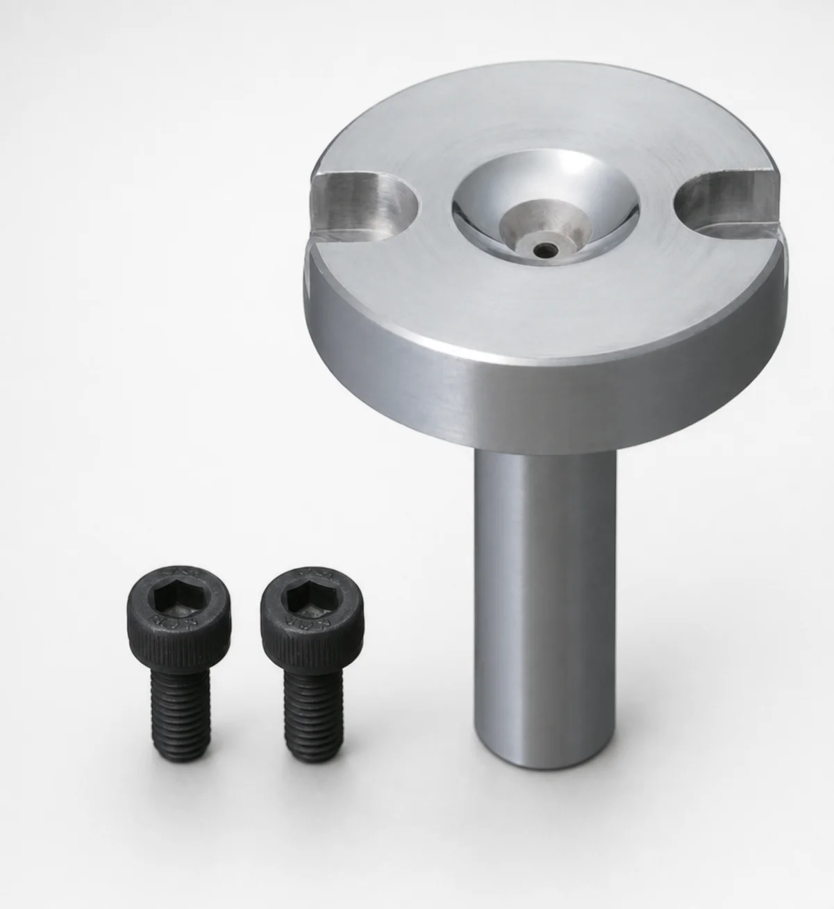
Bolt Fixing Sprue Bushings - Flange Thickness 10 mm
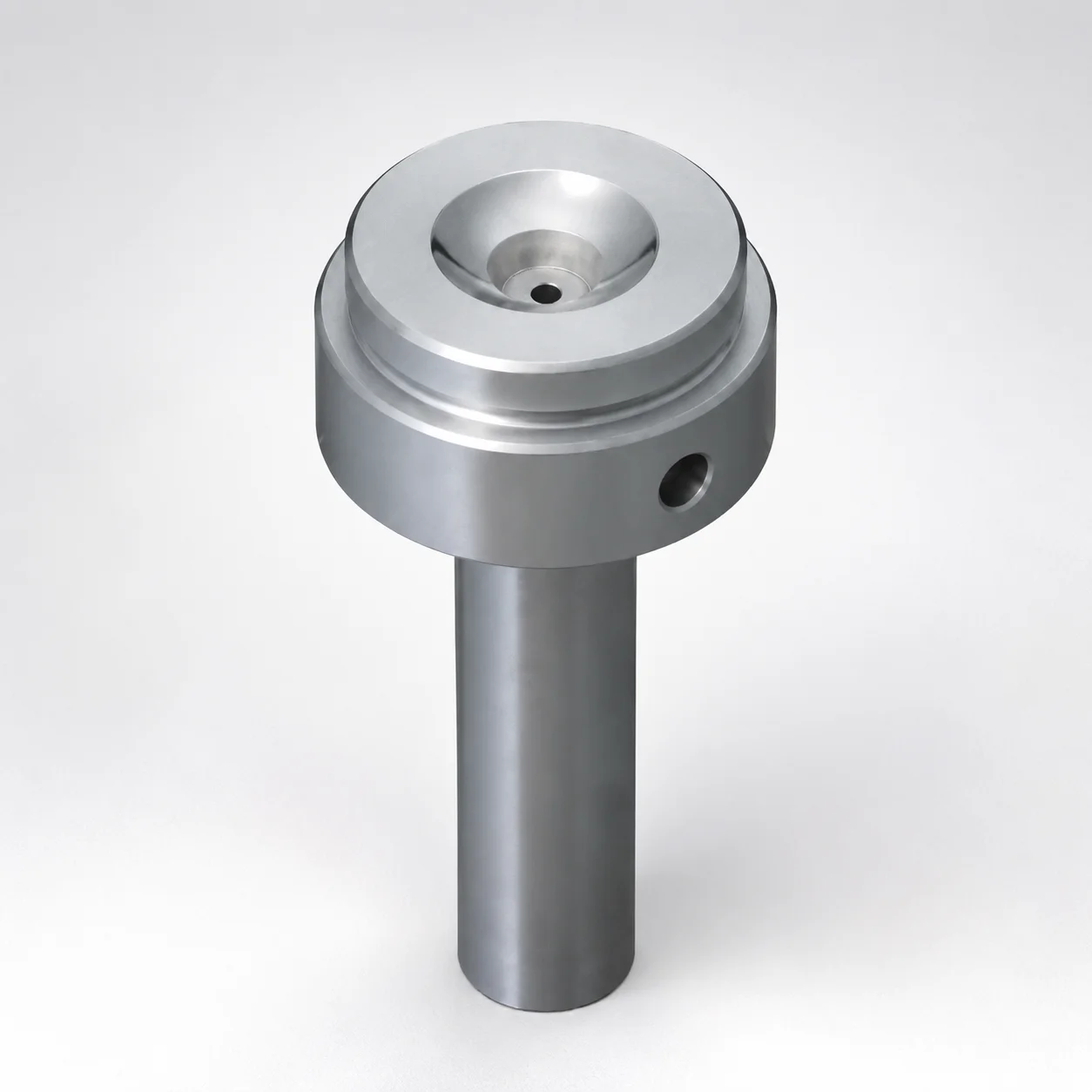
Sprue Bushings Shoulder Type - Flange Thickness 15 mm
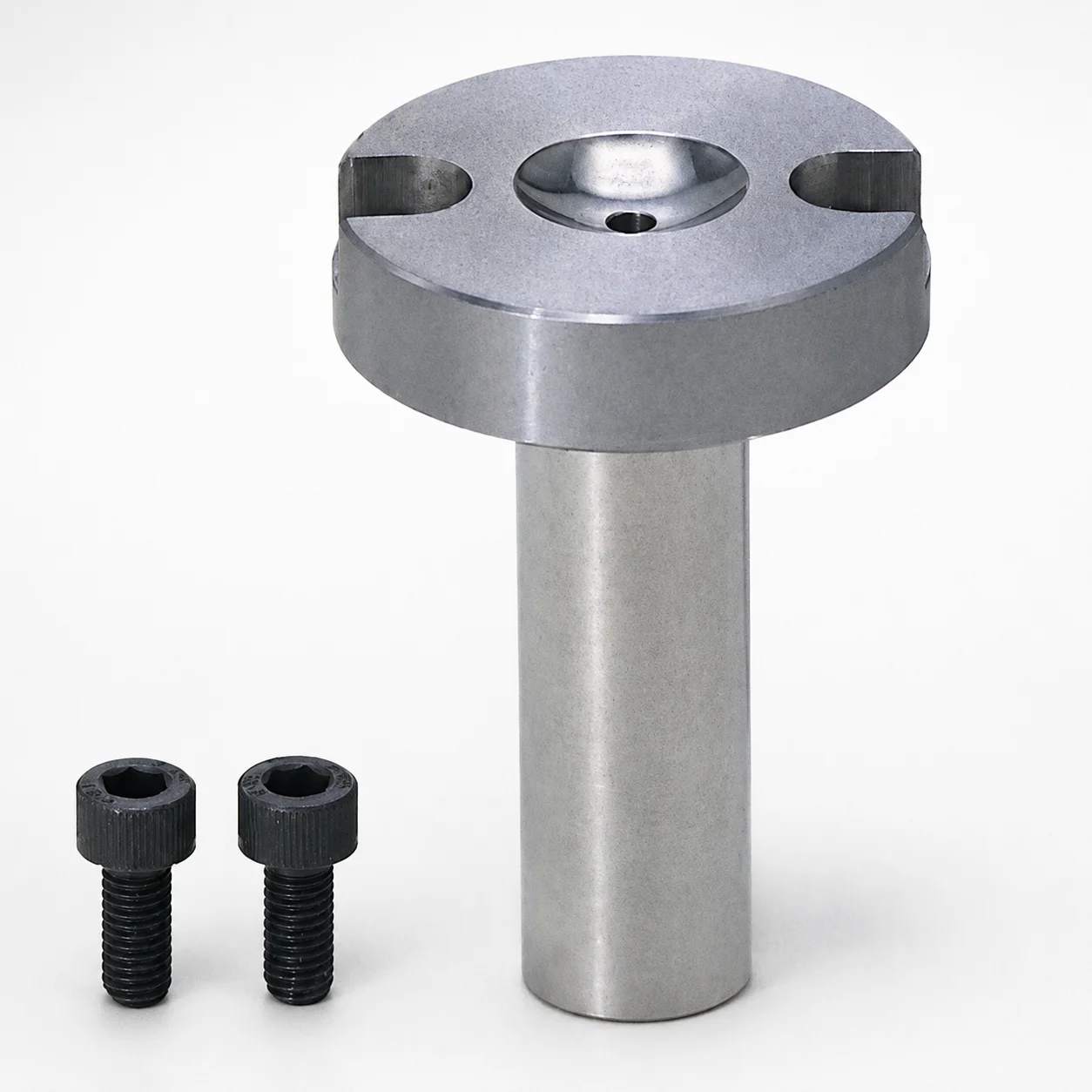
Sprue Bushings - Bolt Fixing Flange Thickness 10 mm
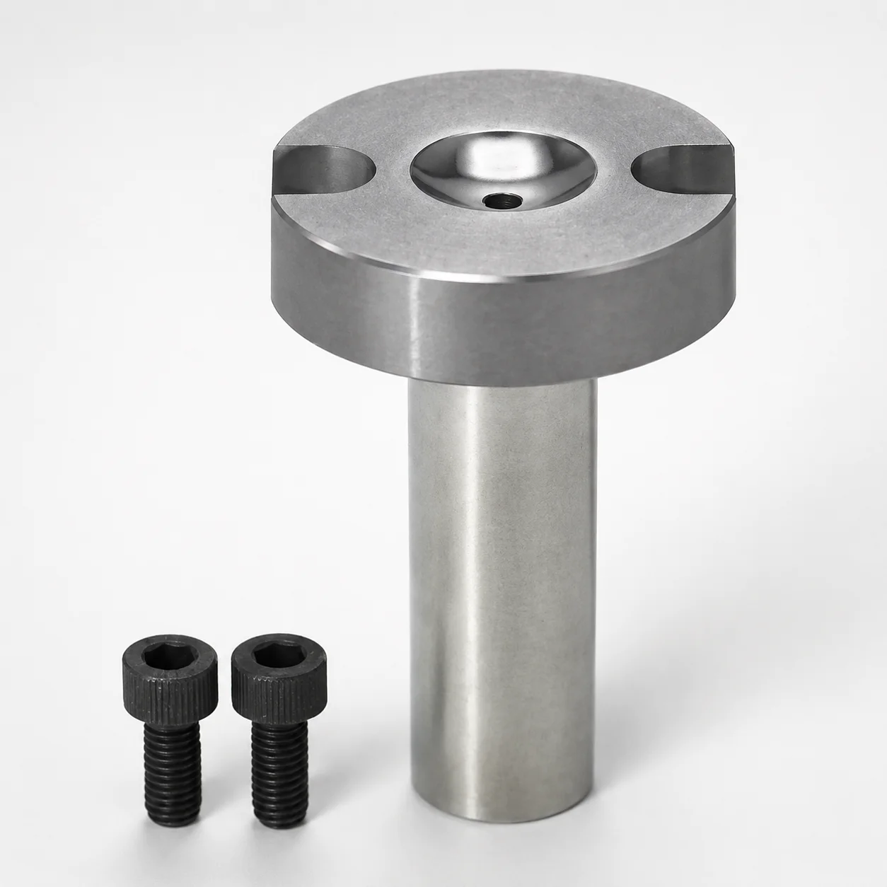
Sprue Bushings - Bolt Fixing, Flange Thickness 10 mm
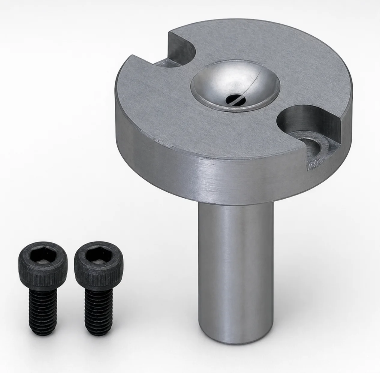
JIS Standard Steel Sprue Bushings - Bolt Fixing String Eliminator (Flange 10 mm)
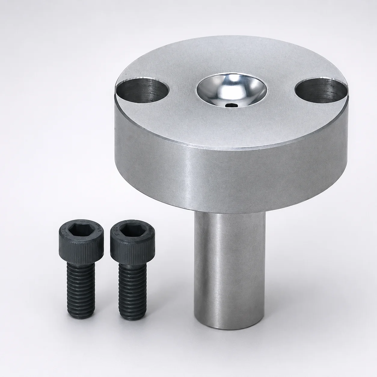
Sprue Bushings - Bolt Fixing, Flange Thickness 20 mm
Need Custom Specifications?
Our engineering team can help with custom configurations, material selection, and volume pricing.