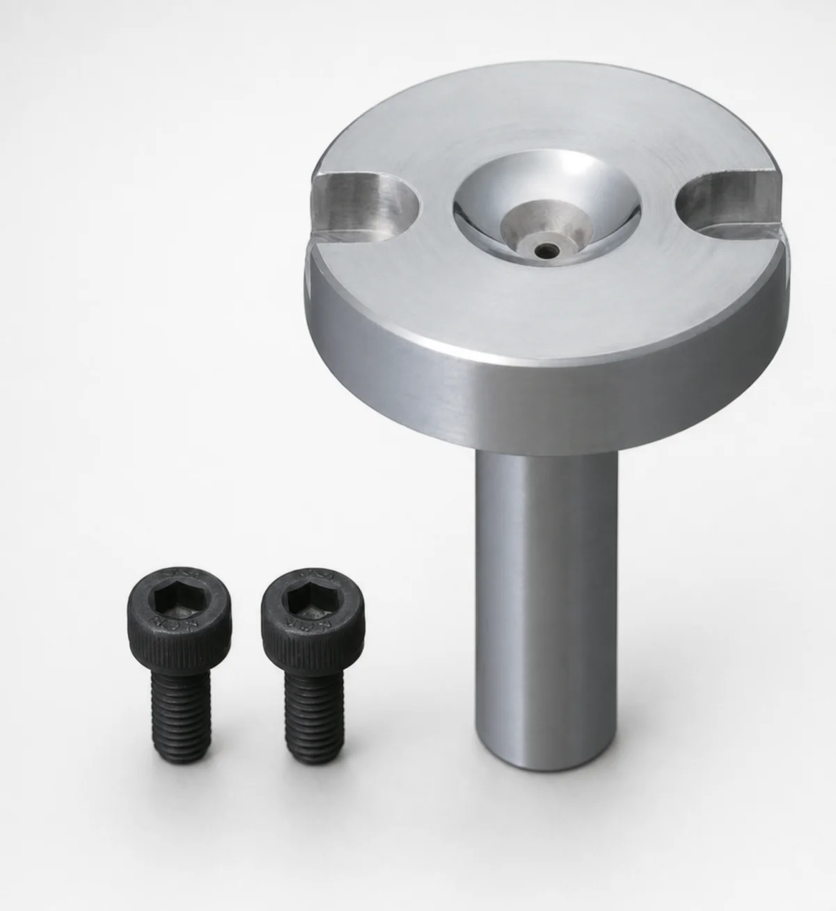
Bolt Fixing Sprue Bushings - Flange Thickness 10 mm
Bolt fixing sprue bushings with 10 mm flange thickness provide a reliable, repeatable interface for sprue and nozzle mounting. The bolt-fixing arrangement helps maintain alignment during molding cycles.
- Designed for normal bolt fixing with a resin pocket nozzle touch
- Environmentally friendly sprue bushing concept for efficient sprue handling
- Supports straight or tapered tip matching to fit common nozzle geometries
- Used in injection mold setups requiring a stable sprue bushing flange interface
Specifications
22 configurations available
| Material | Tip Matching Shape | D (Shaft Diameter) (mm) | L (Bearing bore length) (mm) | A (Taper angle at sprue) (°) | F (Resin pocket depth) (mm) | G (Taper angle) (°) | P (Sprue diameter) (mm) | SR (Nozzle part) (mm) | V (Tip diameter) (mm) | type |
|---|---|---|---|---|---|---|---|---|---|---|
| SKD61 | Straight | 8 | 0 ~ 80 | 0.5 ~ 3 | 0.3 ~ 2 | - | 2 ~ 3 | 10.5 ~ 11 | - | - |
| SKD61 | Straight | 10 | 0 ~ 120 | 0.5 ~ 4 | 0.3 ~ 2 | - | 2 ~ 3 | 10.5 ~ 11 | - | - |
| SKD61 | Straight | 12 | 0 ~ 150 | 0.5 ~ 4 | 0.3 ~ 2 | - | 2 ~ 3 | 10.5 ~ 11 | - | - |
| SKD61 | Straight | 13 | 0 ~ 150 | 0.5 ~ 4 | 0.3 ~ 2 | - | 2 ~ 3 | 10.5 ~ 11 | - | - |
| SKD61 | Straight | 16 | 0 ~ 150 | 0.5 ~ 4 | 0.3 ~ 2 | - | 2 ~ 3 | 10.5 ~ 11 | - | - |
| SKD61 | Straight | 20 | 0 ~ 200 | 0.5 ~ 4 | 0.3 ~ 2 | - | 2 ~ 3 | 10.5 ~ 11 | - | - |
| HPM1 Equivalent | Straight | 8 | 0 ~ 80 | 0.5 ~ 3 | 0.3 ~ 2 | - | 2 ~ 3 | 10.5 ~ 11 | - | - |
| HPM1 Equivalent | Straight | 10 | 0 ~ 120 | 0.5 ~ 4 | 0.3 ~ 2 | - | 2 ~ 3 | 10.5 ~ 11 | - | - |
| HPM1 Equivalent | Straight | 12 | 0 ~ 150 | 0.5 ~ 4 | 0.3 ~ 2 | - | 2 ~ 3 | 10.5 ~ 11 | - | - |
| HPM1 Equivalent | Straight | 13 | 0 ~ 150 | 0.5 ~ 4 | 0.3 ~ 2 | - | 2 ~ 3 | 10.5 ~ 11 | - | - |
| HPM1 Equivalent | Straight | 16 | 0 ~ 150 | 0.5 ~ 4 | 0.3 ~ 2 | - | 2 ~ 3 | 10.5 ~ 11 | - | - |
| HPM1 Equivalent | Straight | 20 | 0 ~ 200 | 0.5 ~ 4 | 0.3 ~ 2 | - | 2 ~ 3 | 10.5 ~ 11 | - | - |
| SKD61 | Tapered | 10 | 0 ~ 120 | 0.5 ~ 4 | 0.3 ~ 2 | 1 ~ 10 | 2 ~ 3 | 10.5 ~ 11 | 4 ~ 10 | - |
| SKD61 | Tapered | 12 | 0 ~ 150 | 0.5 ~ 4 | 0.3 ~ 2 | 1 ~ 10 | 2 ~ 3 | 10.5 ~ 11 | 4 ~ 13 | - |
| SKD61 | Tapered | 13 | 0 ~ 150 | 0.5 ~ 4 | 0.3 ~ 2 | 1 ~ 10 | 2 ~ 3 | 10.5 ~ 11 | 4 ~ 13 | - |
| SKD61 | Tapered | 16 | 0 ~ 150 | 0.5 ~ 4 | 0.3 ~ 2 | 1 ~ 10 | 2 ~ 3 | 10.5 ~ 11 | 4 ~ 16 | - |
| SKD61 | Tapered | 20 | 0 ~ 200 | 0.5 ~ 4 | 0.3 ~ 2 | 1 ~ 10 | 2 ~ 3 | 10.5 ~ 11 | 4 ~ 20 | - |
| HPM1 Equivalent | Tapered | 10 | 0 ~ 120 | 0.5 ~ 4 | 0.3 ~ 2 | 1 ~ 10 | 2 ~ 3 | 10.5 ~ 11 | 4 ~ 10 | - |
| HPM1 Equivalent | Tapered | 12 | 0 ~ 150 | 0.5 ~ 4 | 0.3 ~ 2 | 1 ~ 10 | 2 ~ 3 | 10.5 ~ 11 | 4 ~ 13 | - |
| HPM1 Equivalent | Tapered | 13 | 0 ~ 150 | 0.5 ~ 4 | 0.3 ~ 2 | 1 ~ 10 | 2 ~ 3 | 10.5 ~ 11 | 4 ~ 13 | - |
| HPM1 Equivalent | Tapered | 16 | 0 ~ 150 | 0.5 ~ 4 | 0.3 ~ 2 | 1 ~ 10 | 2 ~ 3 | 10.5 ~ 11 | 4 ~ 16 | - |
| HPM1 Equivalent | Tapered | 20 | 0 ~ 200 | 0.5 ~ 4 | 0.3 ~ 2 | 1 ~ 10 | 2 ~ 3 | 10.5 ~ 11 | 4 ~ 20 | - |
Product Guide
Application Scenarios+
Bolt fixing sprue bushings are installed at the mold’s sprue-to-nozzle interface to create a rigid, repeatable positional reference during injection cycles. This 10 mm flange thickness variant is well suited for press-fit or bolt-stabilized nozzle mounting where consistent alignment reduces shear at the resin entry and helps maintain sprue formation.
- Automotive and appliance connector molds: Use the bolt-fixing interface with a resin pocket nozzle touch to keep the sprue channel concentric under repeated thermal expansion.
- General-purpose industrial housings: The available straight and tapered tip matching shapes support compatibility with common nozzle geometries, helping achieve stable sprue connection across varying taper requirements.
- High-throughput sprue handling setups: The fixed sprue diameter range (2–3 mm) and resin pocket depth (0.3–2 mm) support controlled melt feeding and consistent runner-to-cavity transfer.
Because the flange provides a stable mounting plane, this product helps reduce misalignment-driven defects such as flash or incomplete sprue merging.
Material & Process Details+
This sprue bushing variant is offered in SKD61 and HPM1 (equivalent), tool steels commonly selected for their combination of hot strength and dimensional stability under repeated molding conditions. For SKD61/HPM1-class steels, hardness is typically targeted in the HRC range around the upper 40s to low/mid 50s after quench and temper (Q&T), balancing wear resistance with toughness.
- SKD61 / HPM1 equivalent: Good resistance to sprue-side wear and heat checking; preferred when durability at elevated temperatures is required.
- Trade-offs: Increasing hardness improves wear resistance but can reduce toughness; maintaining Q&T practice helps manage chipping risk at the resin-pocket and taper surfaces.
- Manufacturing/finishing: Common practice is precision turning/boring for the bearing bore and tip features, followed by Q&T to the specified hardness, then final inspection to ensure nozzle-pocket geometry compatibility.
Actual hardness and heat-treatment targets should be confirmed against the supplier’s lot certificate for your specific SKD61 or HPM1 batch.
Sizing & Selection Guide+
To select the correct bolt fixing sprue bushing dimensions, match the shaft diameter (D), bearing bore length (L), and tip features to the nozzle and front-end sprue assembly geometry in your mold.
- Shaft diameter (D): Choose from 8, 10, 12, 13, 16, 20 mm based on the nozzle guide or mounting bore requirements.
- Bearing bore length (L): Select within the available ranges: 0–80, 0–120, 0–150, or 0–200 mm to achieve the required engagement length and support stability.
- Sprue and resin pocket interface: Confirm P (sprue diameter) = 2–3 mm and F (resin pocket depth) = 0.3–2 mm to control melt entry and prevent over/under-engagement.
- Nozzle taper compatibility: Set A (taper angle at sprue) = 0.5–3° (up to 0.5–4°) and G (taper angle) = 1–10°. Choose tip matching shape as straight or tapered, and select V (tip diameter) = 4–10, 4–13, 4–16, or 4–20 mm to suit your nozzle tip.
Use your nozzle’s measured contact/taper geometry as the primary reference; then verify the sprue diameter (2–3 mm) and pocket depth (0.3–2 mm) to ensure proper resin merging. Tight-fit features typically require attention to molding assembly tolerances to maintain concentricity.
Frequently Asked Questions
Which material option (SKD61 vs HPM1 equivalent) is typically preferred for sprue bushing wear at the nozzle contact area?+
The product is offered in SKD61 or HPM1 equivalent tool steels, both selected for hot strength and resistance to sprue-side wear. For both options, hardness after quench and temper is used to balance wear resistance with toughness at the resin pocket and taper surfaces.
Confirm the exact lot hardness (HRC) via the material/heat-treatment certificate if you are targeting a specific wear rate or chipping risk profile.
How do I choose between straight and tapered tip matching shapes for nozzle compatibility?+
Select tip matching shape based on your nozzle’s physical interface. The product supports straight and tapered tip matching, and the tapered option requires you to align A (0.5–3°, up to 0.5–4°) and G (1–10°).
Then choose the corresponding V (tip diameter) range (4–10, 4–13, 4–16, or 4–20 mm) to ensure correct contact during melt entry.
What dimension ranges matter most when designing for correct resin pocket depth and sprue diameter?+
Use the fixed interface parameters to control the resin entry point: F (resin pocket depth) = 0.3–2 mm and P (sprue diameter) = 2–3 mm. These directly affect how the nozzle pocket engages the bushing and how the sprue forms.
Mismatch can lead to poor merging; validate your assembly against the nozzle’s pocket geometry and measured sprue diameter requirement.
How should I select the bushing bearing bore length (L) for stable nozzle alignment with the 10 mm flange?+
Pick L (bearing bore length) from the available options: 0–80, 0–120, 0–150, or 0–200 mm. Longer engagement generally supports stiffness and positional stability under thermal cycling, which is critical for repeatable nozzle alignment.
After selecting L, ensure the D (shaft diameter) matches your mounting bore requirement (8, 10, 12, 13, 16, 20 mm).
How do D (shaft diameter) and V (tip diameter) interact when selecting the correct variant?+
D (shaft diameter) controls the guide/mounting fit and available installation size, while V controls the contacting tip geometry. Choose D = 8, 10, 12, 13, 16, or 20 mm for the mounting interface, then select V within the matching range (4–10, 4–13, 4–16, or 4–20 mm) consistent with your nozzle tip.
For tapered configurations, also align A and G so the contact angle matches the nozzle mating surface.
Related Products
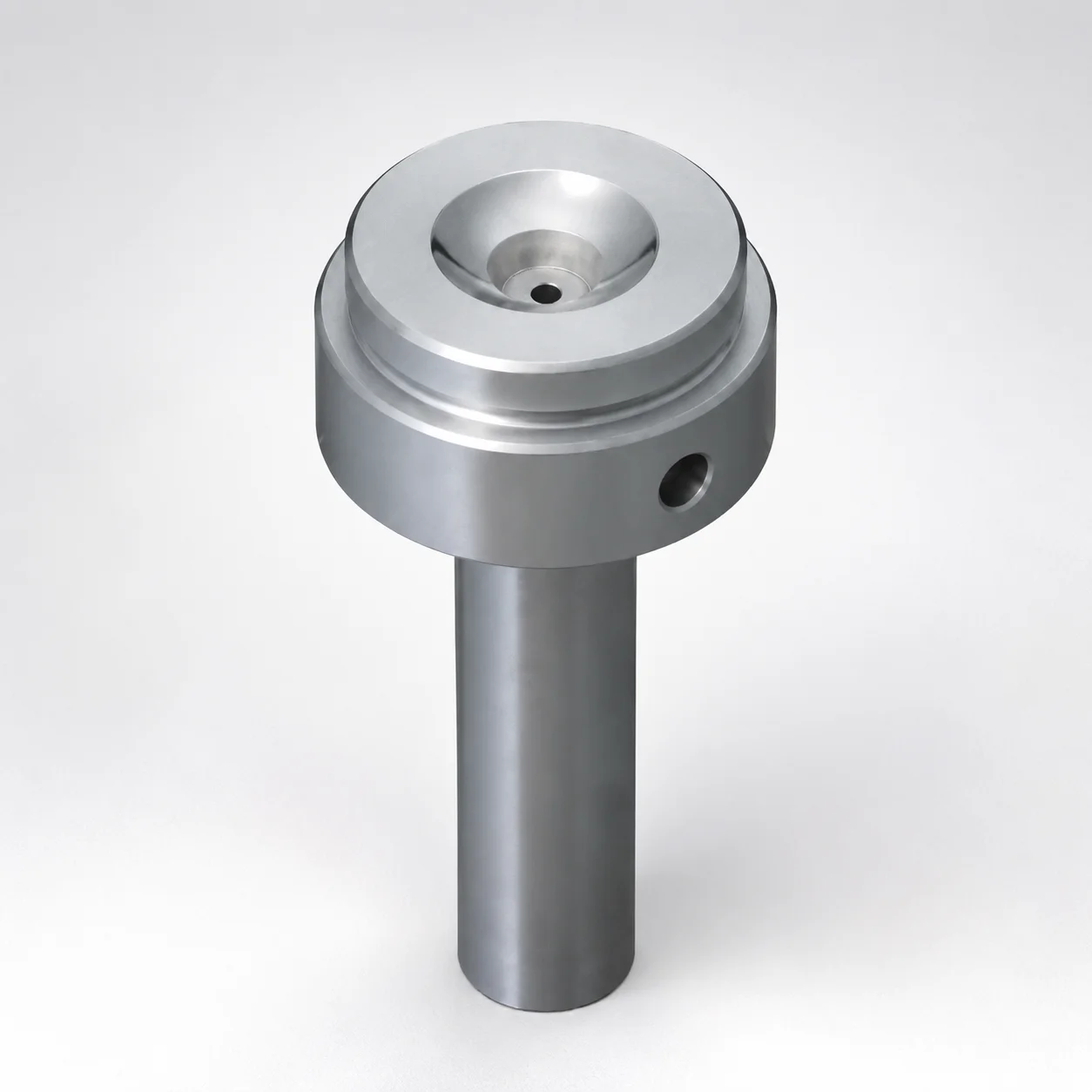
Sprue Bushings Shoulder Type - Flange Thickness 15 mm
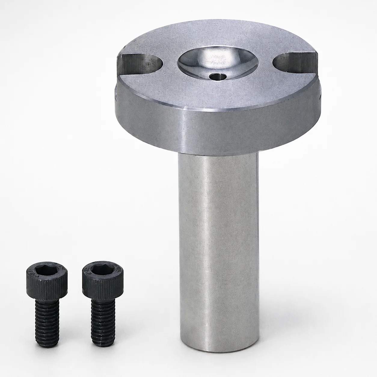
Sprue Bushings - Bolt Fixing Flange Thickness 10 mm
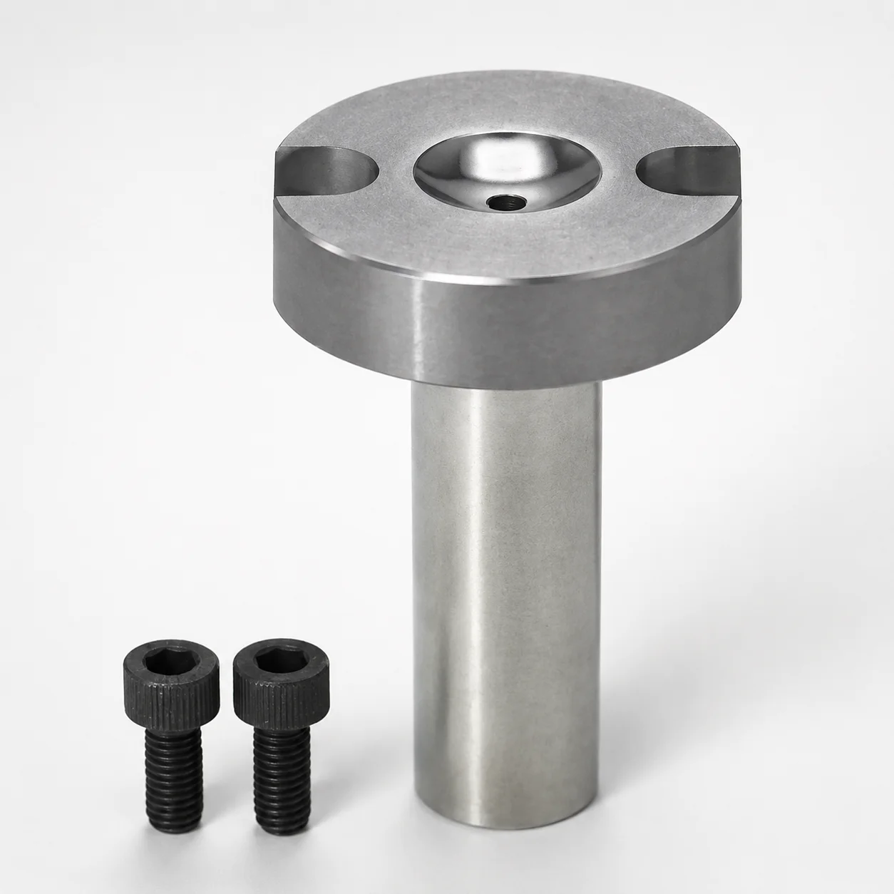
Sprue Bushings - Bolt Fixing, Flange Thickness 10 mm
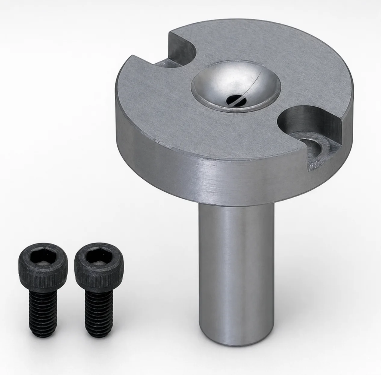
JIS Standard Steel Sprue Bushings - Bolt Fixing String Eliminator (Flange 10 mm)
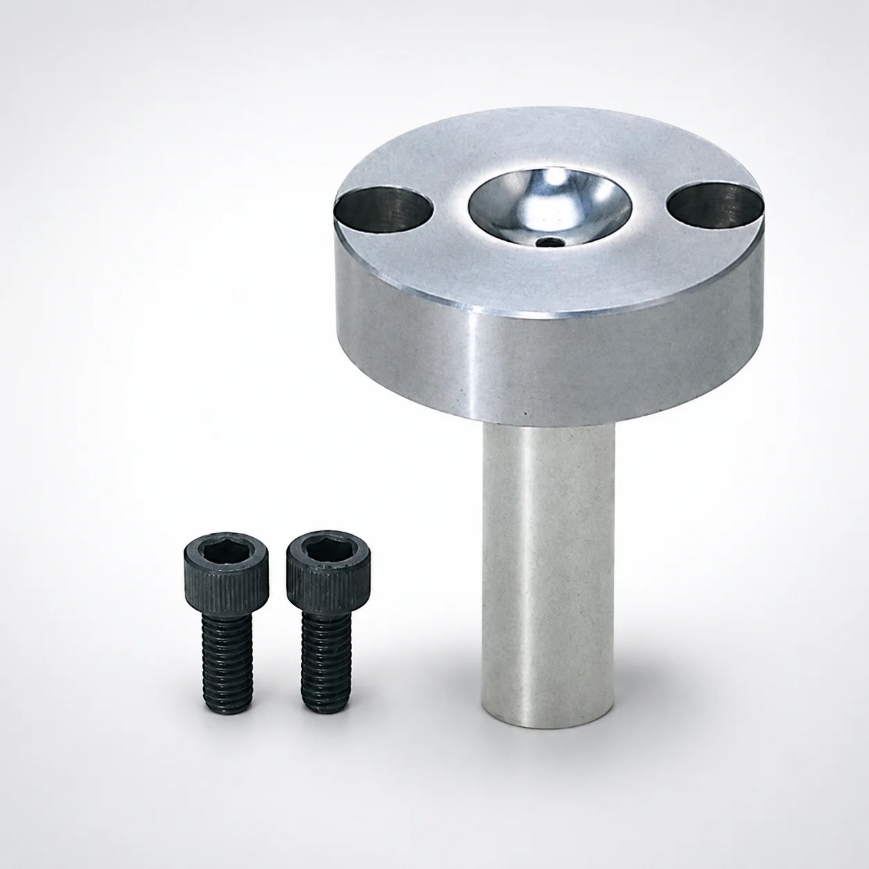
Sprue Bushings - Bolt Fixing Flange Thickness 15 mm
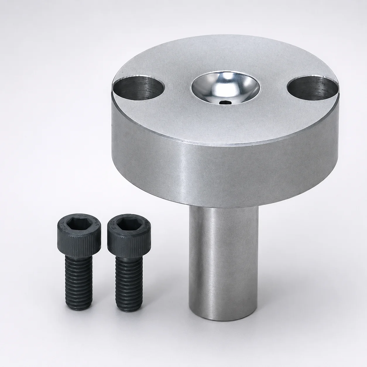
Sprue Bushings - Bolt Fixing, Flange Thickness 20 mm
Need Custom Specifications?
Our engineering team can help with custom configurations, material selection, and volume pricing.