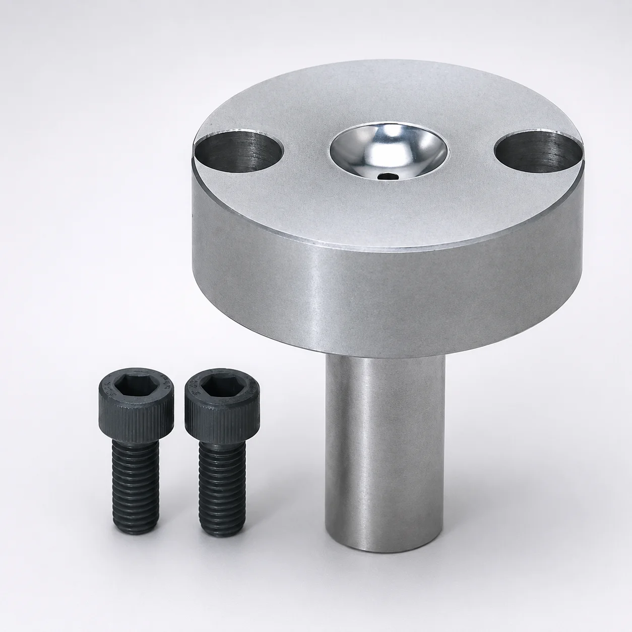
Sprue Bushings - Bolt Fixing, Flange Thickness 20 mm
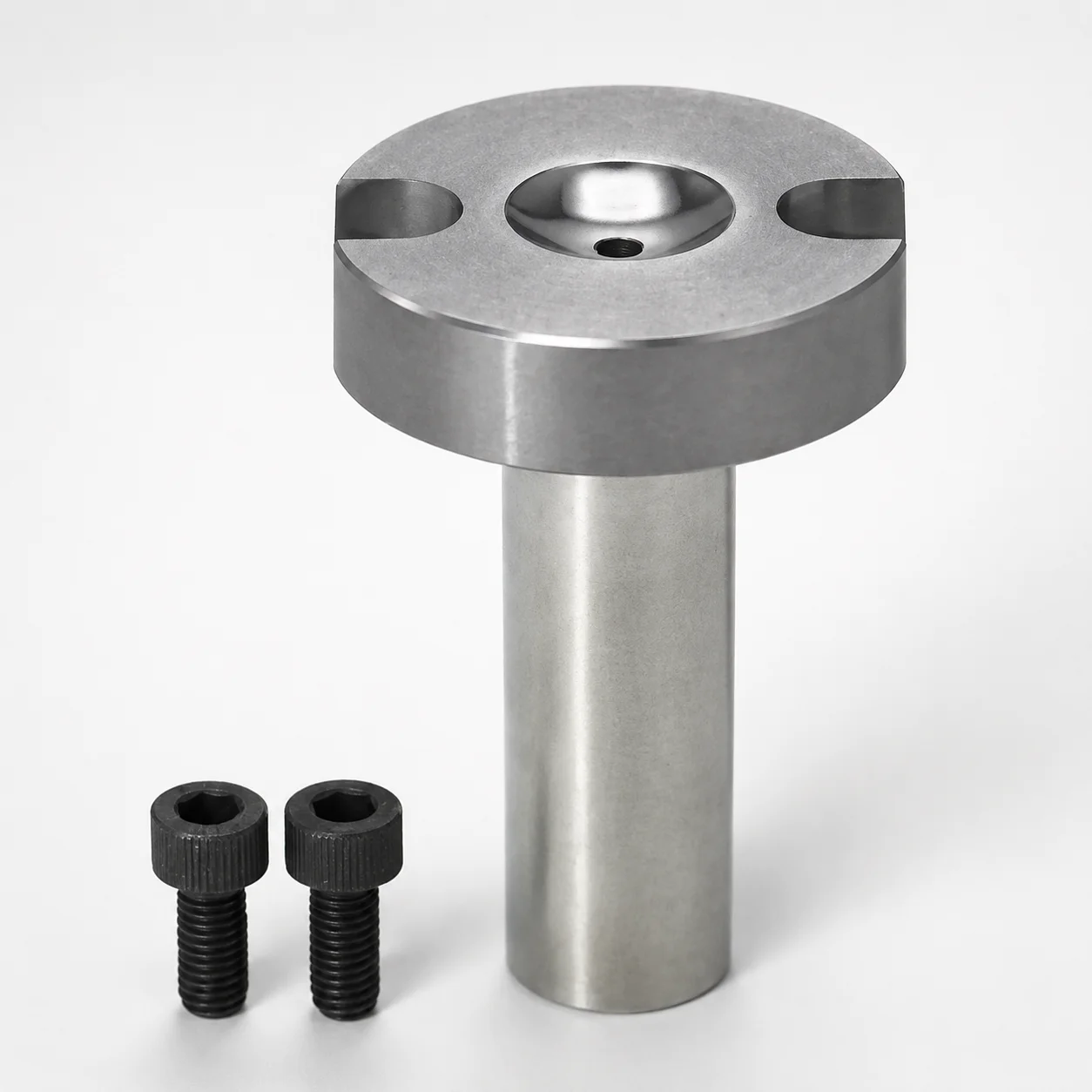
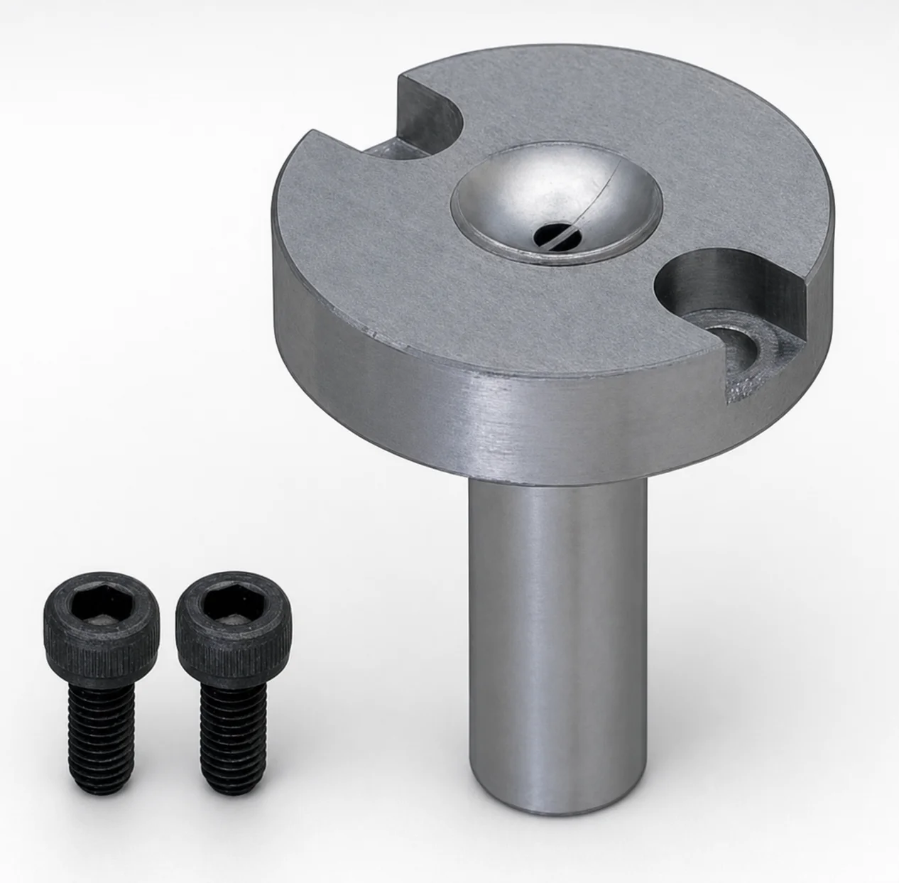
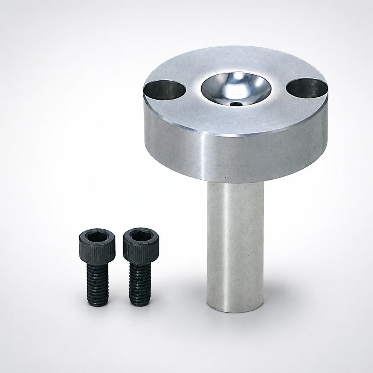
Sprue Bushings - Bolt Fixing, Flange Thickness 20 mm are designed to support stable, bolt-secured installation in sprue locating systems. The fixed flange thickness helps maintain consistent alignment for repeatable mold setup.
- Flange-mount bolt fixing for secure sprue bushing retention
- Steel options (S45C or HPM1 equivalent) for reliable mechanical performance
- Straight or tapered tip matching to suit different nozzle interfaces
- Supports normal or string eliminator nozzle-touch configurations
Specifications
24 configurations available
| Material | Tip Matching Shape | Nozzle Touch Part Specification | D (Shaft Diameter) (mm) | L (Bearing bore length) (mm) | A (Taper angle at sprue) (°) | G (Taper angle) (°) | P (Sprue diameter) (mm) | SR (Nozzle part) (mm) | V (Tip diameter) (mm) | type |
|---|---|---|---|---|---|---|---|---|---|---|
| S45C | Straight | Normal | 20 | 30 ~ 200 | 2 ~ 4 | - | 3 ~ 8 | 0 ~ 23 | - | - |
| S45C | Straight | Normal | 25 | 30 ~ 200 | 2 ~ 4 | - | 3 ~ 8 | 0 ~ 23 | - | - |
| S45C | Straight | Normal | 30 | 30 ~ 200 | 2 ~ 4 | - | 3 ~ 8 | 0 ~ 23 | - | - |
| S45C | Straight | String eliminator | 20 | 30 ~ 200 | 2 ~ 4 | - | 3 ~ 8 | 0 ~ 23 | - | - |
| S45C | Straight | String eliminator | 25 | 30 ~ 200 | 2 ~ 4 | - | 3 ~ 8 | 0 ~ 23 | - | - |
| S45C | Straight | String eliminator | 30 | 30 ~ 200 | 2 ~ 4 | - | 3 ~ 8 | 0 ~ 23 | - | - |
| HPM1 Equivalent | Straight | Normal | 20 | 30 ~ 200 | 2 ~ 4 | - | 3 ~ 8 | 0 ~ 23 | - | - |
| HPM1 Equivalent | Straight | Normal | 25 | 30 ~ 200 | 2 ~ 4 | - | 3 ~ 8 | 0 ~ 23 | - | - |
| HPM1 Equivalent | Straight | Normal | 30 | 30 ~ 200 | 2 ~ 4 | - | 3 ~ 8 | 0 ~ 23 | - | - |
| HPM1 Equivalent | Straight | String eliminator | 20 | 30 ~ 200 | 2 ~ 4 | - | 3 ~ 8 | 0 ~ 23 | - | - |
| HPM1 Equivalent | Straight | String eliminator | 25 | 30 ~ 200 | 2 ~ 4 | - | 3 ~ 8 | 0 ~ 23 | - | - |
| HPM1 Equivalent | Straight | String eliminator | 30 | 30 ~ 200 | 2 ~ 4 | - | 3 ~ 8 | 0 ~ 23 | - | - |
| S45C | Tapered | Normal | 20 | 30 ~ 200 | 2 ~ 4 | 1 ~ 10 | 3 ~ 8 | 0 ~ 23 | 5 ~ 19.9 | - |
| S45C | Tapered | Normal | 25 | 30 ~ 200 | 2 ~ 4 | 1 ~ 10 | 3 ~ 8 | 0 ~ 23 | 5 ~ 24.9 | - |
| S45C | Tapered | Normal | 30 | 30 ~ 200 | 2 ~ 4 | 1 ~ 10 | 3 ~ 8 | 0 ~ 23 | 5 ~ 29.9 | - |
| S45C | Tapered | String eliminator | 20 | 30 ~ 200 | 2 ~ 4 | 1 ~ 10 | 3 ~ 8 | 0 ~ 23 | 5 ~ 19.9 | - |
| S45C | Tapered | String eliminator | 25 | 30 ~ 200 | 2 ~ 4 | 1 ~ 10 | 3 ~ 8 | 0 ~ 23 | 5 ~ 24.9 | - |
| S45C | Tapered | String eliminator | 30 | 30 ~ 200 | 2 ~ 4 | 1 ~ 10 | 3 ~ 8 | 0 ~ 23 | 5 ~ 29.9 | - |
| HPM1 Equivalent | Tapered | Normal | 20 | 30 ~ 200 | 2 ~ 4 | 1 ~ 10 | 3 ~ 8 | 0 ~ 23 | 5 ~ 19.9 | - |
| HPM1 Equivalent | Tapered | Normal | 25 | 30 ~ 200 | 2 ~ 4 | 1 ~ 10 | 3 ~ 8 | 0 ~ 23 | 5 ~ 24.9 | - |
| HPM1 Equivalent | Tapered | Normal | 30 | 30 ~ 200 | 2 ~ 4 | 1 ~ 10 | 3 ~ 8 | 0 ~ 23 | 5 ~ 29.9 | - |
| HPM1 Equivalent | Tapered | String eliminator | 20 | 30 ~ 200 | 2 ~ 4 | 1 ~ 10 | 3 ~ 8 | 0 ~ 23 | 5 ~ 19.9 | - |
| HPM1 Equivalent | Tapered | String eliminator | 25 | 30 ~ 200 | 2 ~ 4 | 1 ~ 10 | 3 ~ 8 | 0 ~ 23 | 5 ~ 24.9 | - |
| HPM1 Equivalent | Tapered | String eliminator | 30 | 30 ~ 200 | 2 ~ 4 | 1 ~ 10 | 3 ~ 8 | 0 ~ 23 | 5 ~ 29.9 | - |
Product Guide
Application Scenarios+
These bolt-fixing sprue bushings are used in injection mold tooling to secure the sprue locating system with a stable, repeatable bolt-mounted interface. The 20 mm flange thickness is intended to maintain consistent alignment during clamping and to reduce positional drift over repeated mold cycles.
- Automotive and general industrial connector molds: When the mold requires reliable nozzle-to-sprue alignment, the availability of straight or tapered tips helps match the nozzle interface and supports repeatable sprue engagement.
- Hot/runner sprue systems with different nozzle touch types: The configuration supports normal and string eliminator nozzle-touch arrangements, helping maintain stable contact while controlling stringing behavior.
- Steel-based molds needing assembly fit stability: The steel material options (S45C or HPM1 equivalent) provide mechanical robustness for frequent maintenance and fixture changes.
Material & Process Details+
This sprue bushing is offered in S45C or HPM1 equivalent, giving designers a choice between general toughness/strength and higher wear-focused performance. S45C (a medium-carbon steel) is commonly used where moderate hardness and good machining are needed; it supports stable assembly under typical clamping loads.
HPM1 equivalent is selected when improved surface durability is beneficial for long production runs involving repeated nozzle touch. In both cases, performance depends on the supplied heat-treated condition and your fixture pressure/usage cycle; hardness must be balanced with toughness to avoid chipping at the taper tip during nozzle engagement.
- Wear resistance vs. toughness trade-off: higher hardness materials generally resist wear better but can reduce impact tolerance if overly hardened.
- Heat treatment state: specify the receiving condition (e.g., pre-hardened or quenched & tempered) to confirm hardness (HRC) and dimensional stability for your nozzle mating parts.
Sizing & Selection Guide+
Select the sprue bushing by matching the shaft diameter D and bearing bore length L to the mold’s sprue locating structure. Available D values are 20, 25, or 30 mm. The L (bearing bore length) is fixed in the range 30 ~ 200 mm, and should be chosen to fully support the locating function without over-penetrating the mold base.
- Taper/sprue geometry matching: Use the provided sprue angle settings A = 2 ~ 4° and taper angle G = 1 ~ 10° to align with your nozzle-to-sprue funnel design.
- Sprue diameter and nozzle part: Match P = 3 ~ 8 mm (sprue diameter) and SR = 0 ~ 23 mm (nozzle part) to ensure the nozzle touch depth and sealing/cone engagement are correct.
- Tip diameter V selection: Choose V from the available ranges (5 ~ 19.9, 5 ~ 24.9, or 5 ~ 29.9) based on the specific nozzle interface envelope.
For proper fit, confirm the mating dimensions and tolerances in your sprue system to avoid excessive clearance at the taper tip, which can affect centering and string control.
Frequently Asked Questions
Which shaft diameter (D) should I choose for my mold’s sprue locating plate?+
How do I select the tip shape and nozzle touch specification for string elimination systems?+
What sprue and taper angles are available, and where do they affect alignment?+
How should I size P (sprue diameter) and V (tip diameter) to avoid under/over engagement?+
What material should I choose: S45C or HPM1 equivalent, and what heat-treatment info is needed?+
Related Products
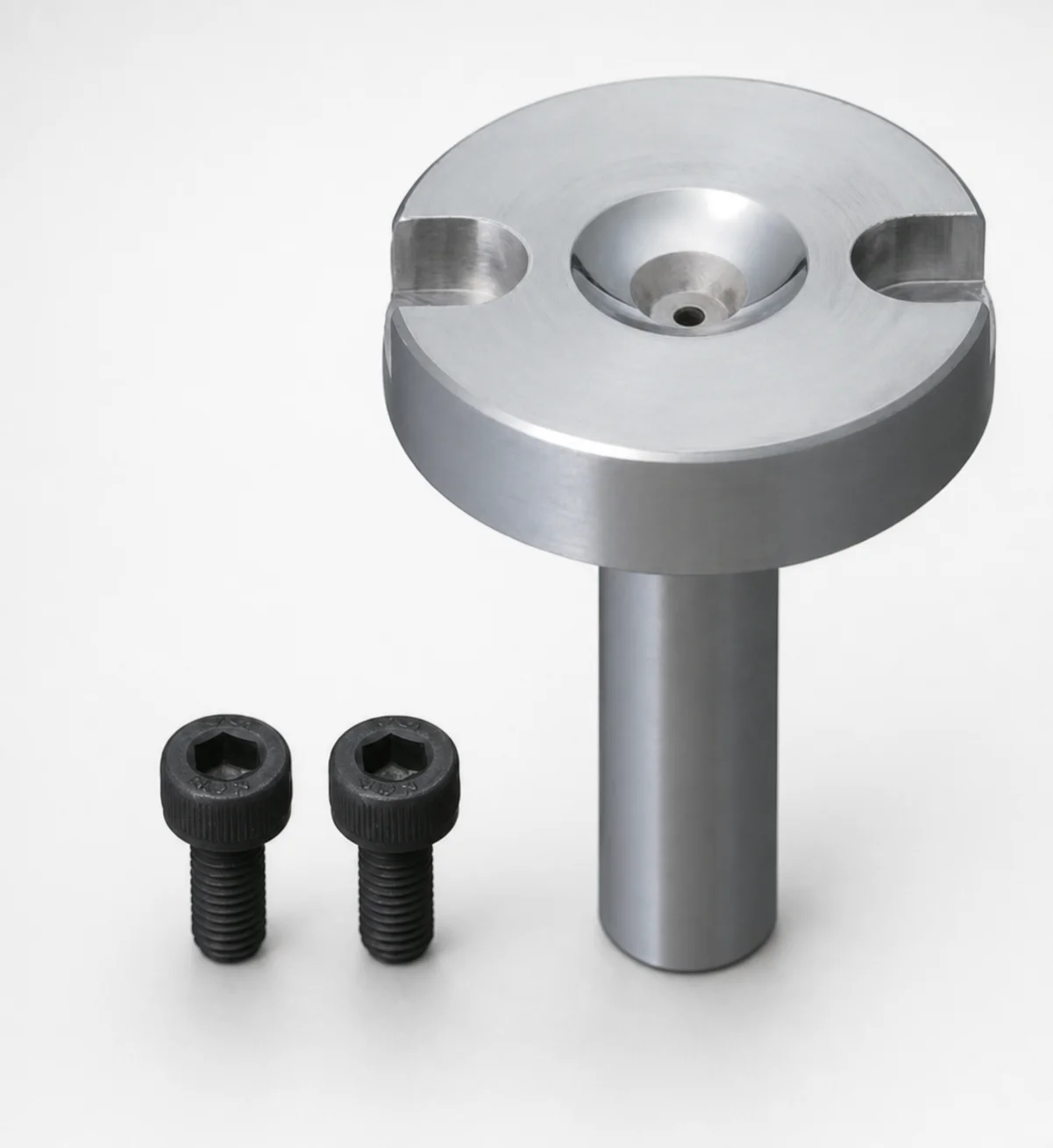
Bolt Fixing Sprue Bushings - Flange Thickness 10 mm
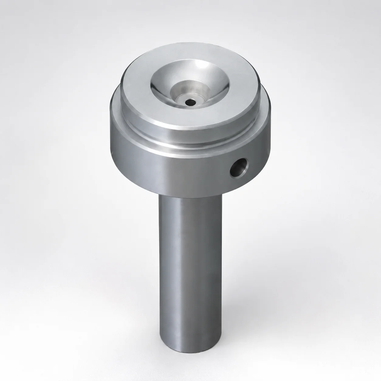
Sprue Bushings Shoulder Type - Flange Thickness 15 mm
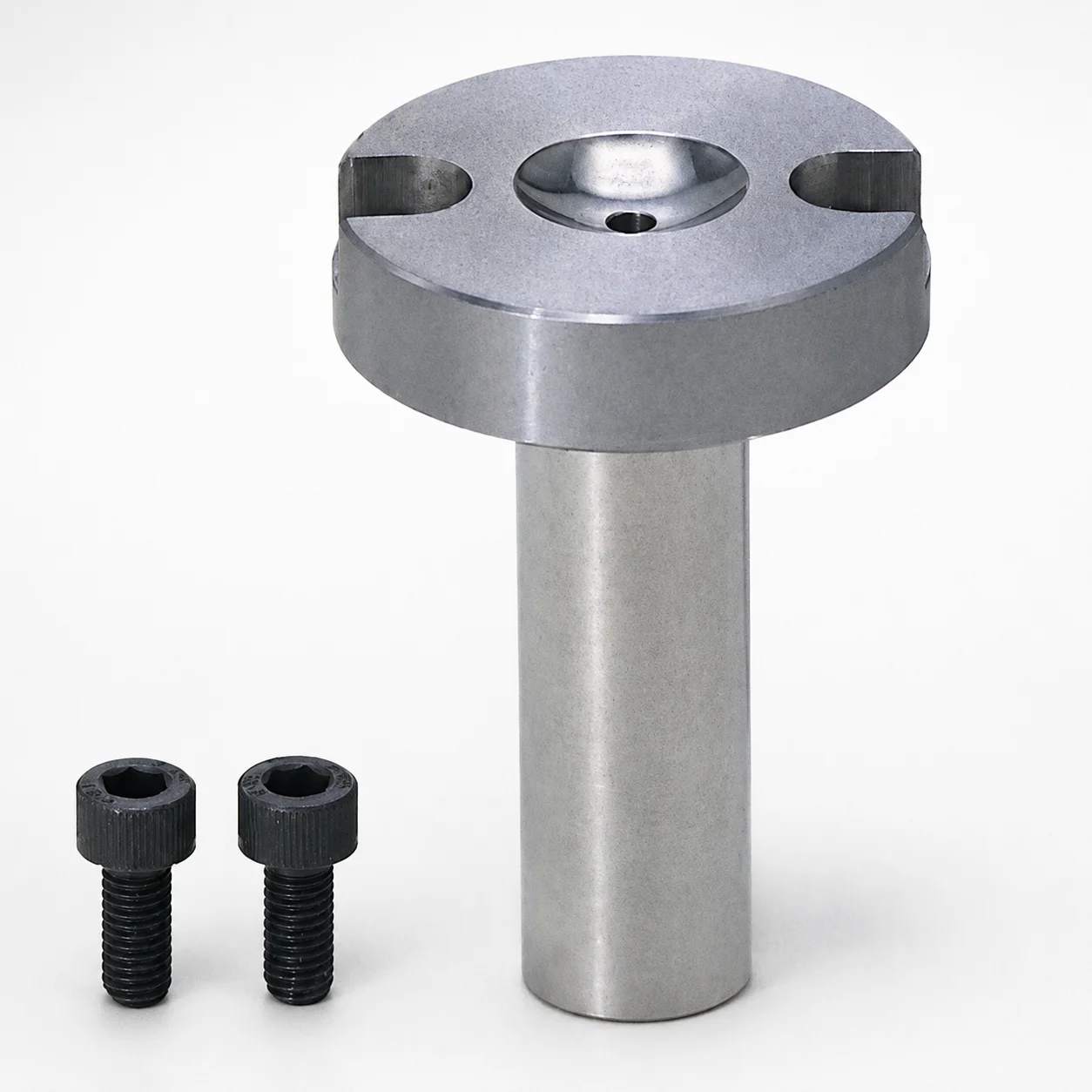
Sprue Bushings - Bolt Fixing Flange Thickness 10 mm
Sprue Bushings - Bolt Fixing, Flange Thickness 10 mm
JIS Standard Steel Sprue Bushings - Bolt Fixing String Eliminator (Flange 10 mm)
Sprue Bushings - Bolt Fixing Flange Thickness 15 mm
Need Custom Specifications?
Our engineering team can help with custom configurations, material selection, and volume pricing.