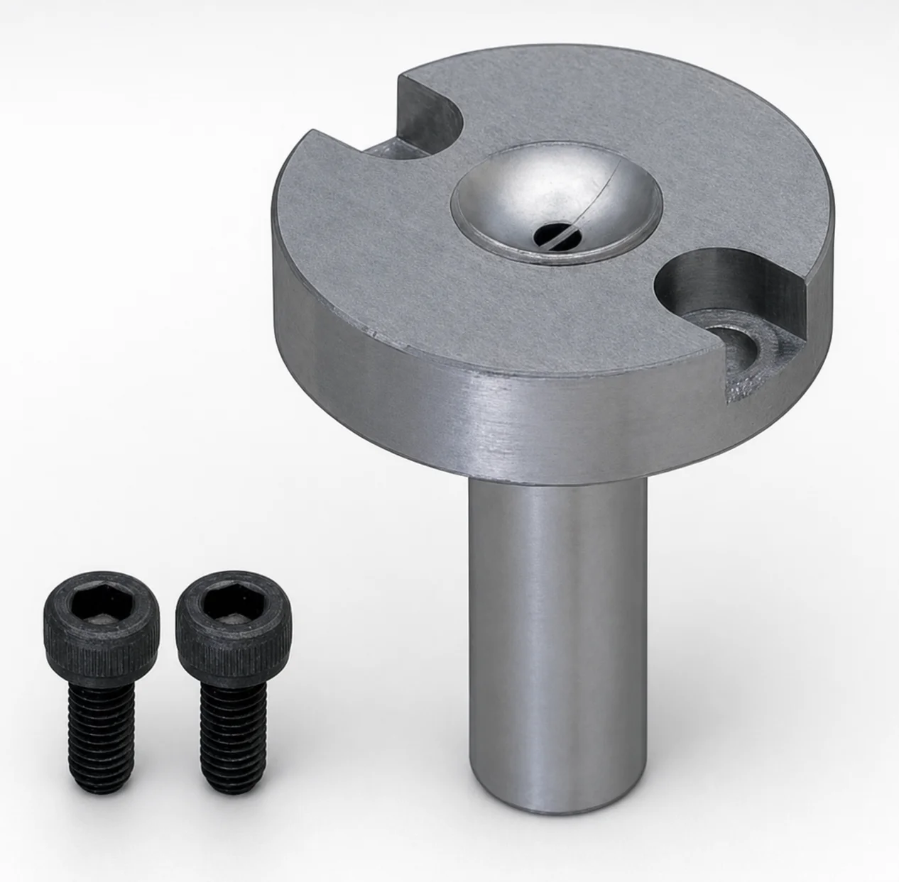
JIS Standard Steel Sprue Bushings - Bolt Fixing String Eliminator (Flange 10 mm)
Sprue bushings - bolt fixing string eliminator (JIS standard steel) are designed for reliable sprue nozzle mounting using a normal bolt connection and a straight tip interface. The 10 mm flange thickness supports consistent positioning during injection molding.
- Bolted fixation with a straight tip matching geometry for stable nozzle alignment
- String eliminator nozzle touch design helps manage stringing at the sprue interface
- 10 mm flange thickness supports mounting rigidity for repeatable assembly
- Built for sprue bushing applications requiring precise, repeatable sprue formation
Specifications
6 configurations available
| Material | D (Shaft Diameter) (mm) | L (Bearing bore length) (mm) | A (Taper angle at sprue) (°) | P (Sprue diameter) (mm) | SR (Nozzle part) (mm) | Y (Thickness of plate with string eliminator) (mm) | type |
|---|---|---|---|---|---|---|---|
| HPM1 Equivalent | 10 | 0 ~ 120 | 0.5 ~ 4 | 2.5 ~ 4.5 | 0 ~ 16 | 0.5 ~ 0.6 | - |
| HPM1 Equivalent | 13 | 0 ~ 150 | 0.5 ~ 4 | 2.5 ~ 4.5 | 0 ~ 16 | 0.5 ~ 0.6 | - |
| HPM1 Equivalent | 16 | 0 ~ 150 | 0.5 ~ 4 | 2.5 ~ 4.5 | 0 ~ 16 | 0.5 ~ 0.6 | - |
| SKD61 | 10 | 0 ~ 120 | 0.5 ~ 4 | 2.5 ~ 4.5 | 0 ~ 16 | 0.5 ~ 0.6 | - |
| SKD61 | 13 | 0 ~ 150 | 0.5 ~ 4 | 2.5 ~ 4.5 | 0 ~ 16 | 0.5 ~ 0.6 | - |
| SKD61 | 16 | 0 ~ 150 | 0.5 ~ 4 | 2.5 ~ 4.5 | 0 ~ 16 | 0.5 ~ 0.6 | - |
Product Guide
Application Scenarios+
This bolt-fixing sprue bushing with string-eliminator interface is used in injection mold tooling where the sprue nozzle must be mounted with repeatable alignment. The straight tip interface and 10 mm flange thickness help maintain concentric positioning between the sprue nozzle and the sprue bushing during high-cycle runs.
Common scenarios include:
- Automotive connector and small housing molds: helps stabilize sprue formation for consistent gate quality, reducing misalignment-induced flow defects.
- Appliance and industrial part molds: the string-eliminator touch geometry supports management of stringing at the sprue interface, improving ejection cleanliness.
- General-purpose production molds: bolted fixation enables straightforward maintenance and reliable reassembly when nozzle/sprue components are serviced.
Designed for a normal bolt connection and a JIS standard steel approach, this variant suits applications that prioritize alignment stability, repeatable assembly, and controlled sprue interface behavior.
Material & Process Details+
Available steels include SKD61 (commonly regarded as an H13-equivalent tool steel for hot work) and an HPM1-equivalent option. These grades are selected for their balance of wear resistance and hot strength, which is important at the sprue/nozzle interface exposed to repeated thermal cycling.
- SKD61 (H13-equivalent): typically quenched and tempered for improved toughness while maintaining good wear performance under repeated heating.
- HPM1-equivalent: generally chosen when a different performance balance is required, such as tailored toughness/edge retention for tooling surfaces.
Hardness and trade-offs: at the hardened & tempered condition, expect strong wear resistance suitable for production sprue interfaces; increasing hardness can reduce toughness, so proper heat treatment is critical for preventing chipping or micro-cracking around the interface.
Sizing & Selection Guide+
Select dimensions by matching the sprue bushing geometry to the sprue nozzle and cavity/core interface requirements. Start with D (shaft diameter) and choose from 10 mm, 13 mm, or 16 mm to fit the bushing pocket and guide features without interference.
- L (bearing bore length): available in 0–120 mm and 0–150 mm ranges—pick length based on how much support length you need for stable nozzle guidance and the effective engagement depth.
- A (taper angle at sprue): fixed range 0.5–4° to match the nozzle/bushing taper mating requirement.
- P (sprue diameter): fixed 2.5–4.5 mm—match to the target sprue size used for consistent flow.
- SR (nozzle part): 0–16 mm for the nozzle-side interface length/portion.
Plate thickness (Y) for the string eliminator is 0.5–0.6 mm. Confirm tolerance/fit at the bolt interface and tip contact surfaces to ensure repeatable alignment under clamping force and thermal expansion.
Frequently Asked Questions
Which shaft diameter (D) should I select for a given sprue nozzle mounting pocket?+
This series is offered with D = 10, 13, or 16 mm. Choose the diameter that matches the bushing pocket/guidance bore so the sprue nozzle can seat concentrically with minimal clearance or interference.
After selecting D, verify that the overall engagement length is achievable within the available L (0–120 or 0–150 mm) range.
How do the taper angle (A) and sprue diameter (P) affect the sprue formation quality?+
The taper angle at the sprue is specified as A = 0.5–4°, and the sprue diameter is P = 2.5–4.5 mm. Correct matching to the corresponding nozzle/bushing mating surfaces helps ensure stable flow and consistent sprue geometry.
Mismatched A or P can contribute to uneven sealing at the interface and variability in gate/sprue quality.
What does the string-eliminator feature change at the sprue interface, and why does Y matter?+
This variant includes a string-eliminator touch design, intended to manage stringing at the sprue interface. The plate thickness with string eliminator is Y = 0.5–0.6 mm, which influences the interaction depth/behavior at the nozzle contact region.
For applications sensitive to sprue stringing, confirm that the nozzle-side interface geometry and SR range are compatible with your tool design.
When should I choose SKD61 versus an HPM1-equivalent for sprue bushings?+
The product listing provides HPM1-equivalent and SKD61 material options. SKD61 is commonly treated as an H13-equivalent tool steel approach, typically quenched and tempered to support a balance of wear resistance and toughness during thermal cycling.
Your selection should reflect how your tool experiences wear versus impact/toughness demands at the sprue/nozzle interface.
How do I confirm interface compatibility using SR and L without hitting alignment issues?+
Use SR (nozzle part) = 0–16 mm to align the nozzle-side interface portion, and use L (bearing bore length) = 0–120 mm or 0–150 mm to provide adequate guidance support depth.
Because the flange thickness is fixed at 10 mm, ensure the bolted mounting and tip contact surfaces are designed so the nozzle seats with stable alignment under clamping pressure.
Related Products
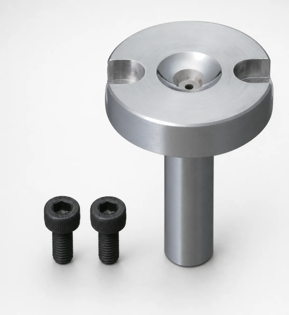
Bolt Fixing Sprue Bushings - Flange Thickness 10 mm
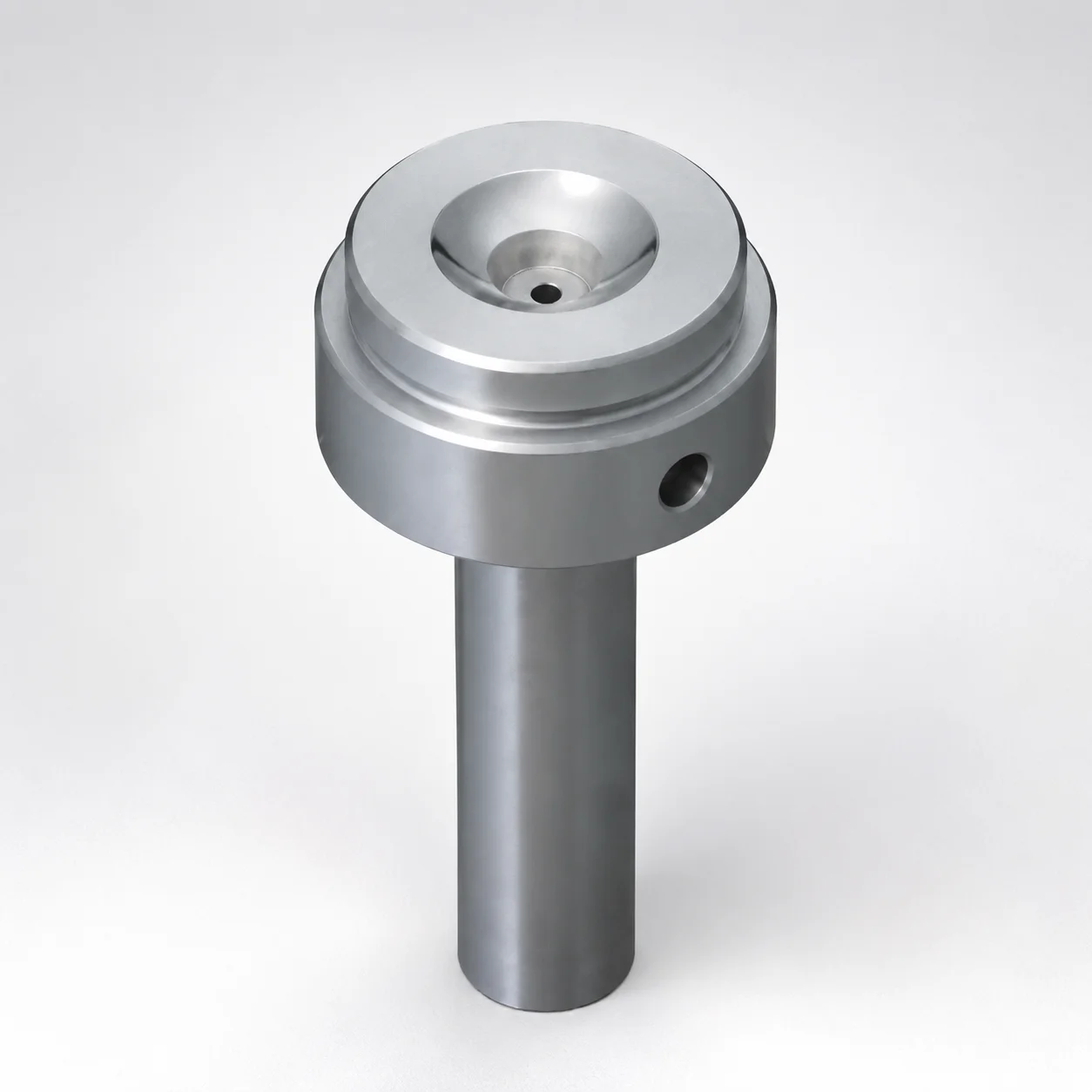
Sprue Bushings Shoulder Type - Flange Thickness 15 mm
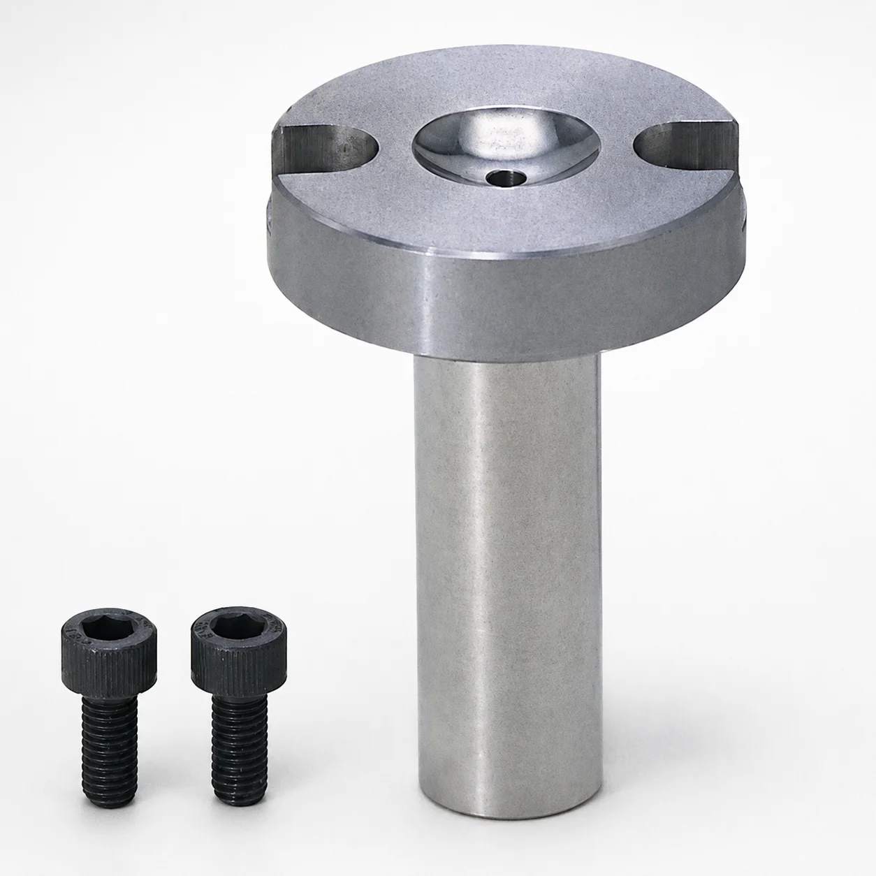
Sprue Bushings - Bolt Fixing Flange Thickness 10 mm
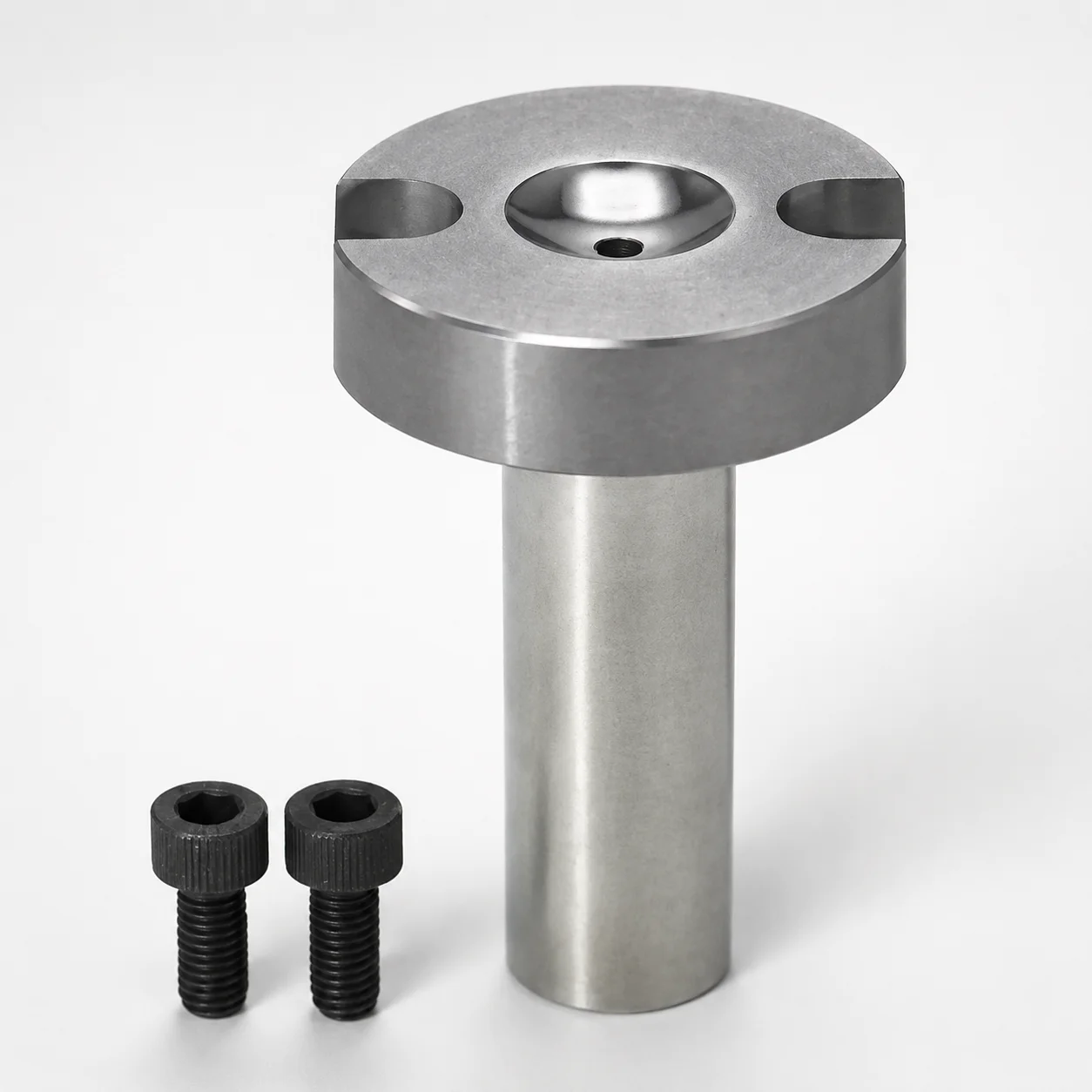
Sprue Bushings - Bolt Fixing, Flange Thickness 10 mm
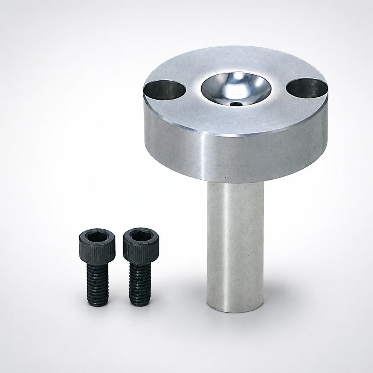
Sprue Bushings - Bolt Fixing Flange Thickness 15 mm
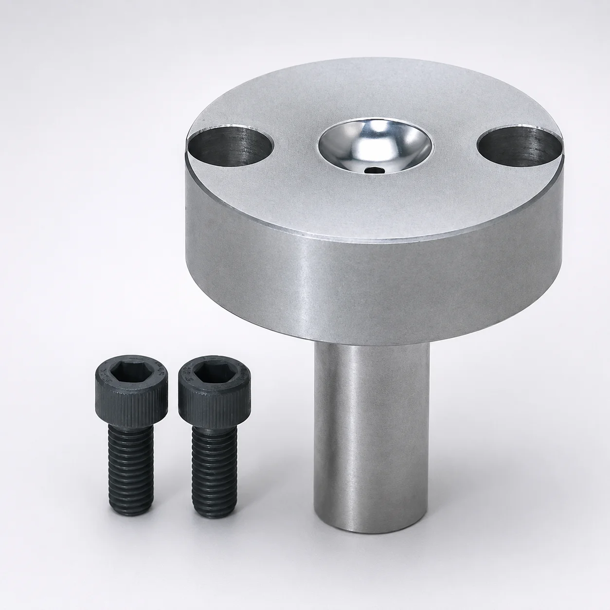
Sprue Bushings - Bolt Fixing, Flange Thickness 20 mm
Need Custom Specifications?
Our engineering team can help with custom configurations, material selection, and volume pricing.