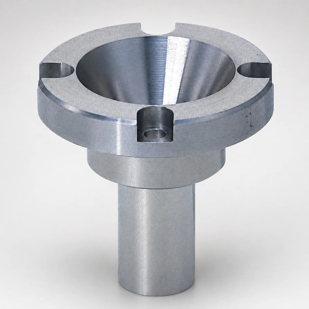
Small Diameter Extended Nozzle Sprue Bushings
Small diameter extended nozzle sprue bushings are extension type tool components designed to support reliable nozzle touch at the sprue bushing interface. They help maintain consistent alignment for smooth mold filling and repeatable production.
- Extension design for small diameter extended nozzle contact during injection molding
- Available with SKD61 steel options to support durability in demanding cycles
- Selectable tip matching profiles including straight and tapered for process fit
- Supports common sprue bushing configurations for efficient sprue formation
Specifications
48 configurations available
| Material | Tip Matching Shape | D (Shaft Diameter) (mm) | A (Taper angle at sprue) (°) | Nozzle type | G (Taper angle) (°) | Dimension L (mm) | P (Sprue diameter) (mm) | V (Tip diameter) (mm) | type |
|---|---|---|---|---|---|---|---|---|---|
| SKD61 | Straight | 10 | 1 ~ 4 | Special nozzle type | - | 21 ~ 61 | 2 ~ 5 | - | - |
| SKD61 | Straight | 13 | 1 ~ 4 | Special nozzle type | - | 21 ~ 61 | 2 ~ 5 | - | - |
| SKD61 | Straight | 16 | 1 ~ 4 | Special nozzle type | - | 21 ~ 61 | 2 ~ 5 | - | - |
| SKD61 | Straight | 20 | 1 ~ 4 | Special nozzle type | - | 21 ~ 61 | 2 ~ 5 | - | - |
| HPM1 Equivalent | Straight | 10 | 1 ~ 4 | Special nozzle type | - | 21 ~ 61 | 2 ~ 5 | - | - |
| HPM1 Equivalent | Straight | 13 | 1 ~ 4 | Special nozzle type | - | 21 ~ 61 | 2 ~ 5 | - | - |
| HPM1 Equivalent | Straight | 16 | 1 ~ 4 | Special nozzle type | - | 21 ~ 61 | 2 ~ 5 | - | - |
| HPM1 Equivalent | Straight | 20 | 1 ~ 4 | Special nozzle type | - | 21 ~ 61 | 2 ~ 5 | - | - |
| SKD61 | Straight | 10 | 1 ~ 4 | Small nozzle type | - | 25 ~ 65 | 2 ~ 5 | - | - |
| SKD61 | Straight | 13 | 1 ~ 4 | Small nozzle type | - | 25 ~ 65 | 2 ~ 5 | - | - |
| SKD61 | Straight | 16 | 1 ~ 4 | Small nozzle type | - | 25 ~ 65 | 2 ~ 5 | - | - |
| SKD61 | Straight | 20 | 1 ~ 4 | Small nozzle type | - | 25 ~ 65 | 2 ~ 5 | - | - |
| SKD61 | Straight | 10 | 1 ~ 4 | Large nozzle type | - | 21 ~ 61 | 2 ~ 5 | - | - |
| SKD61 | Straight | 13 | 1 ~ 4 | Large nozzle type | - | 21 ~ 61 | 2 ~ 5 | - | - |
| SKD61 | Straight | 16 | 1 ~ 4 | Large nozzle type | - | 21 ~ 61 | 2 ~ 5 | - | - |
| SKD61 | Straight | 20 | 1 ~ 4 | Large nozzle type | - | 21 ~ 61 | 2 ~ 5 | - | - |
| HPM1 Equivalent | Straight | 10 | 1 ~ 4 | Large nozzle type | - | 21 ~ 61 | 2 ~ 5 | - | - |
| HPM1 Equivalent | Straight | 13 | 1 ~ 4 | Large nozzle type | - | 21 ~ 61 | 2 ~ 5 | - | - |
| HPM1 Equivalent | Straight | 16 | 1 ~ 4 | Large nozzle type | - | 21 ~ 61 | 2 ~ 5 | - | - |
| HPM1 Equivalent | Straight | 20 | 1 ~ 4 | Large nozzle type | - | 21 ~ 61 | 2 ~ 5 | - | - |
| SKD61 | Tapered | 10 | 1 ~ 4 | Large nozzle type | 1 ~ 10 | 26 ~ 61 | 2 ~ 5 | 4.3 ~ 9.9 | - |
| SKD61 | Tapered | 13 | 1 ~ 4 | Large nozzle type | 1 ~ 10 | 26 ~ 61 | 2 ~ 5 | 4.3 ~ 12.9 | - |
| SKD61 | Tapered | 16 | 1 ~ 4 | Large nozzle type | 1 ~ 10 | 26 ~ 61 | 2 ~ 5 | 4.3 ~ 15.9 | - |
| SKD61 | Tapered | 20 | 1 ~ 4 | Large nozzle type | 1 ~ 10 | 26 ~ 61 | 2 ~ 5 | 4.3 ~ 19.9 | - |
| HPM1 Equivalent | Tapered | 10 | 1 ~ 4 | Large nozzle type | 1 ~ 10 | 26 ~ 61 | 2 ~ 5 | 4.3 ~ 9.9 | - |
| HPM1 Equivalent | Tapered | 13 | 1 ~ 4 | Large nozzle type | 1 ~ 10 | 26 ~ 61 | 2 ~ 5 | 4.3 ~ 12.9 | - |
| HPM1 Equivalent | Tapered | 16 | 1 ~ 4 | Large nozzle type | 1 ~ 10 | 26 ~ 61 | 2 ~ 5 | 4.3 ~ 15.9 | - |
| HPM1 Equivalent | Tapered | 20 | 1 ~ 4 | Large nozzle type | 1 ~ 10 | 26 ~ 61 | 2 ~ 5 | 4.3 ~ 19.9 | - |
| HPM1 Equivalent | Straight | 10 | 1 ~ 4 | Small nozzle type | - | 25 ~ 65 | 2 ~ 5 | - | - |
| HPM1 Equivalent | Straight | 13 | 1 ~ 4 | Small nozzle type | - | 25 ~ 65 | 2 ~ 5 | - | - |
| HPM1 Equivalent | Straight | 16 | 1 ~ 4 | Small nozzle type | - | 25 ~ 65 | 2 ~ 5 | - | - |
| HPM1 Equivalent | Straight | 20 | 1 ~ 4 | Small nozzle type | - | 25 ~ 65 | 2 ~ 5 | - | - |
| SKD61 | Tapered | 10 | 1 ~ 4 | Special nozzle type | 1 ~ 10 | 26 ~ 61 | 2 ~ 5 | 4.3 ~ 9.9 | - |
| SKD61 | Tapered | 13 | 1 ~ 4 | Special nozzle type | 1 ~ 10 | 26 ~ 61 | 2 ~ 5 | 4.3 ~ 12.9 | - |
| SKD61 | Tapered | 16 | 1 ~ 4 | Special nozzle type | 1 ~ 10 | 26 ~ 61 | 2 ~ 5 | 4.3 ~ 15.9 | - |
| SKD61 | Tapered | 20 | 1 ~ 4 | Special nozzle type | 1 ~ 10 | 26 ~ 61 | 2 ~ 5 | 4.3 ~ 19.9 | - |
| HPM1 Equivalent | Tapered | 10 | 1 ~ 4 | Special nozzle type | 1 ~ 10 | 26 ~ 61 | 2 ~ 5 | 4.3 ~ 9.9 | - |
| HPM1 Equivalent | Tapered | 13 | 1 ~ 4 | Special nozzle type | 1 ~ 10 | 26 ~ 61 | 2 ~ 5 | 4.3 ~ 12.9 | - |
| HPM1 Equivalent | Tapered | 16 | 1 ~ 4 | Special nozzle type | 1 ~ 10 | 26 ~ 61 | 2 ~ 5 | 4.3 ~ 15.9 | - |
| HPM1 Equivalent | Tapered | 20 | 1 ~ 4 | Special nozzle type | 1 ~ 10 | 26 ~ 61 | 2 ~ 5 | 4.3 ~ 19.9 | - |
| SKD61 | Tapered | 10 | 1 ~ 4 | Small nozzle type | 1 ~ 10 | 30 ~ 65 | 2 ~ 5 | 4.3 ~ 9.9 | - |
| SKD61 | Tapered | 13 | 1 ~ 4 | Small nozzle type | 1 ~ 10 | 30 ~ 65 | 2 ~ 5 | 4.3 ~ 12.9 | - |
| SKD61 | Tapered | 16 | 1 ~ 4 | Small nozzle type | 1 ~ 10 | 30 ~ 65 | 2 ~ 5 | 4.3 ~ 15.9 | - |
| SKD61 | Tapered | 20 | 1 ~ 4 | Small nozzle type | 1 ~ 10 | 30 ~ 65 | 2 ~ 5 | 4.3 ~ 19.9 | - |
| HPM1 Equivalent | Tapered | 10 | 1 ~ 4 | Small nozzle type | 1 ~ 10 | 30 ~ 65 | 2 ~ 5 | 4.3 ~ 9.9 | - |
| HPM1 Equivalent | Tapered | 13 | 1 ~ 4 | Small nozzle type | 1 ~ 10 | 30 ~ 65 | 2 ~ 5 | 4.3 ~ 12.9 | - |
| HPM1 Equivalent | Tapered | 16 | 1 ~ 4 | Small nozzle type | 1 ~ 10 | 30 ~ 65 | 2 ~ 5 | 4.3 ~ 15.9 | - |
| HPM1 Equivalent | Tapered | 20 | 1 ~ 4 | Small nozzle type | 1 ~ 10 | 30 ~ 65 | 2 ~ 5 | 4.3 ~ 19.9 | - |
Product Guide
Application Scenarios+
These small-diameter extended nozzle sprue bushings are used in injection mold tooling where stable nozzle touch at the sprue interface is critical. The extension geometry helps maintain alignment between the nozzle and the sprue bushing during repeated clamp/shot cycles, supporting consistent sprue formation and smoother melt flow.
- Automotive connector and sensor molds: Ideal for compact gate systems that require small sprue diameters (P = 2–5 mm) and repeatable nozzle contact using straight or tapered tip profiles matched to the nozzle geometry.
- Small-part consumer and appliance injection: Suitable when small-to-large nozzle types must be accommodated via compatible nozzle type selection and tip diameter range (V = 4.3–19.9 mm), helping reduce misalignment-related filling variation.
- Industrial housings with high cycle durability needs: The available SKD61 variant supports longer service life in demanding cycles, where wear at the touch area and thermal fatigue resistance are priorities.
Choose the variant with the required tip matching shape (straight/tapered) and the appropriate shaft diameter to ensure precise extension alignment.
Material & Process Details+
This series is available in SKD61 and an HPM1-equivalent material option (per the provided specification). SKD61 is a hot-work tool steel widely used for injection mold components due to its balance of wear resistance and toughness under cyclic thermal loads.
- Heat treatment state: Typically supplied as a tool-steel grade suitable for quench-and-temper service in die/mold applications; final hardness should be confirmed against your supplier’s material cert for the exact lot.
- Wear vs. toughness trade-off: Harder conditions improve resistance to erosion and galling at the nozzle-touch region, while maintaining adequate toughness helps prevent chipping around the sprue interface.
- Hardness (HRC): Not specified in the provided data; request hardness certification for the SKD61 or HPM1-equivalent option to match your wear/impact requirements.
For extremely wear-focused applications, select the material option and heat-treatment condition that provides the highest practical surface hardness while still meeting impact resistance needs.
Sizing & Selection Guide+
Select dimensions by matching the nozzle-touch interface geometry and sprue formation requirements of your cavity/core gate system. Start with the shaft diameter D because it governs fit and guidance through the sprue bushing pocket: available D = 10, 13, 16, 20 mm.
- Choose length L (extension reach): Use the available ranges to set nozzle touch depth and engagement: L = 21–61, 25–65, 26–61, or 30–65 mm depending on the configuration.
- Match sprue/interface angles: The taper angle at sprue is fixed as A = 1–4°, while the overall taper angle G = 1–10° guides how the tapered interface seats (when using tapered tip matching).
- Match sprue diameter and tip geometry: Ensure P = 2–5 mm for sprue formation, then select the tip diameter V from the available ranges (4.3–9.9, 4.3–12.9, 4.3–15.9, 4.3–19.9 mm) and the required tip matching shape (straight or tapered).
Tolerance/fit requirements are not provided in the data; verify your mold-pocket tolerances and alignment features with your design drawings to prevent nozzle-touch mismatch or excessive clearance.
Frequently Asked Questions
Which tip matching shape (straight vs. tapered) should I select for extension nozzle touch?+
How do I choose the correct sprue bushing shaft diameter (D) for my mold pocket?+
What sprue diameter range (P) is compatible with these small-diameter extended sprue bushings?+
When should I choose SKD61 versus the HPM1-equivalent material option?+
How do I determine the correct extension length (L) for nozzle engagement?+
Related Products
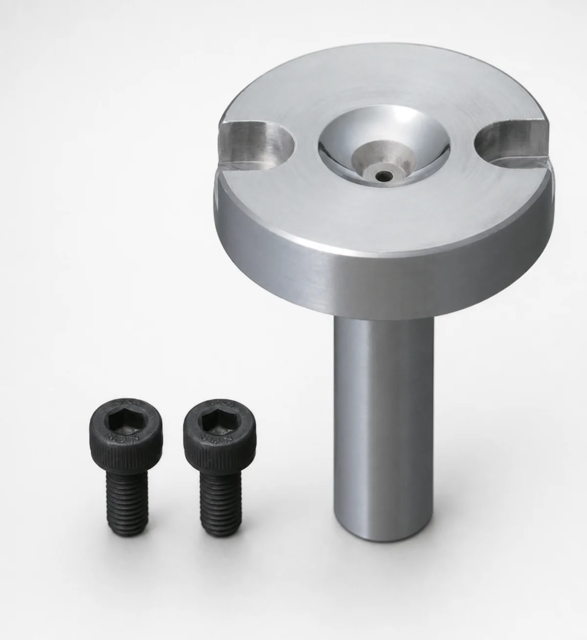
Bolt Fixing Sprue Bushings - Flange Thickness 10 mm
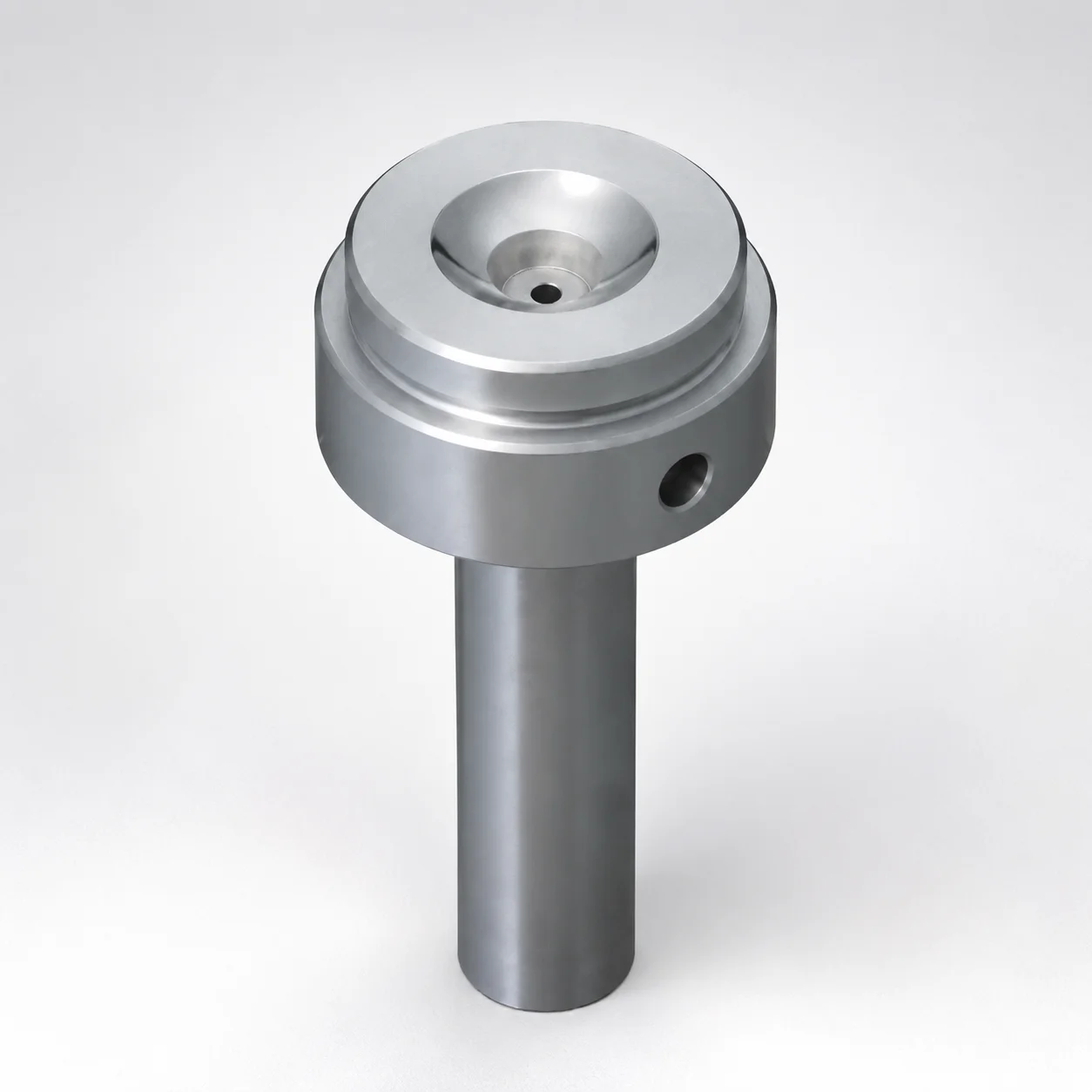
Sprue Bushings Shoulder Type - Flange Thickness 15 mm
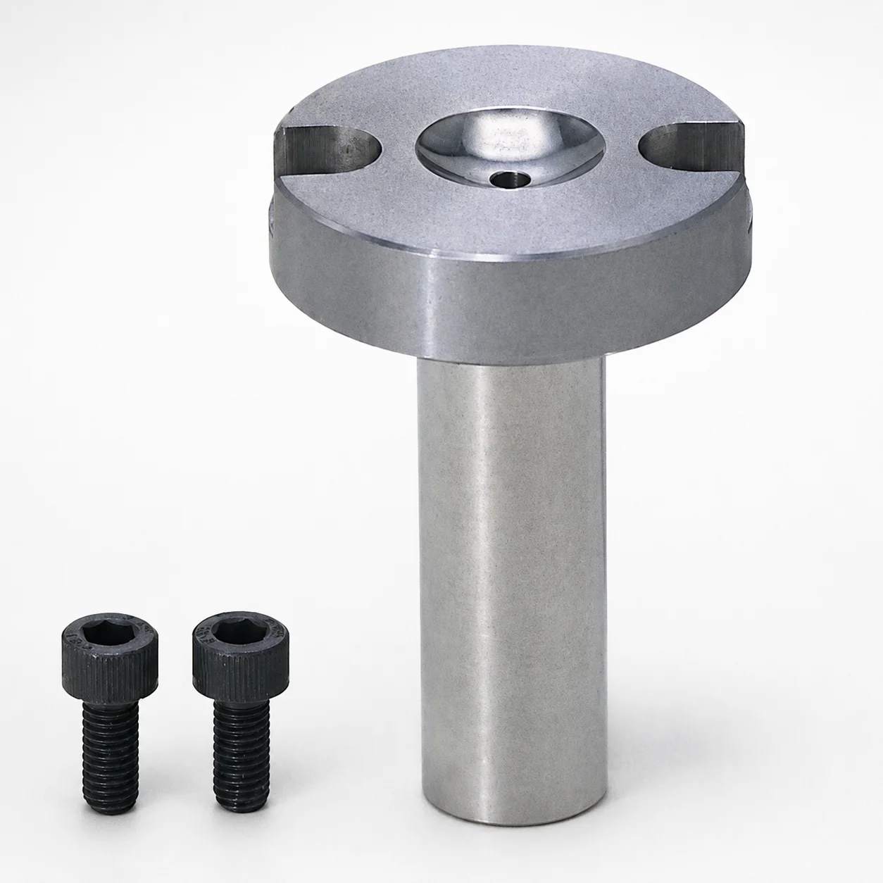
Sprue Bushings - Bolt Fixing Flange Thickness 10 mm
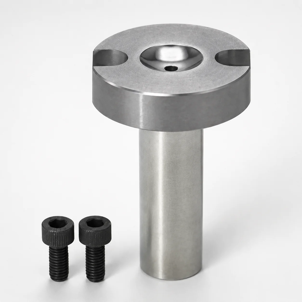
Sprue Bushings - Bolt Fixing, Flange Thickness 10 mm
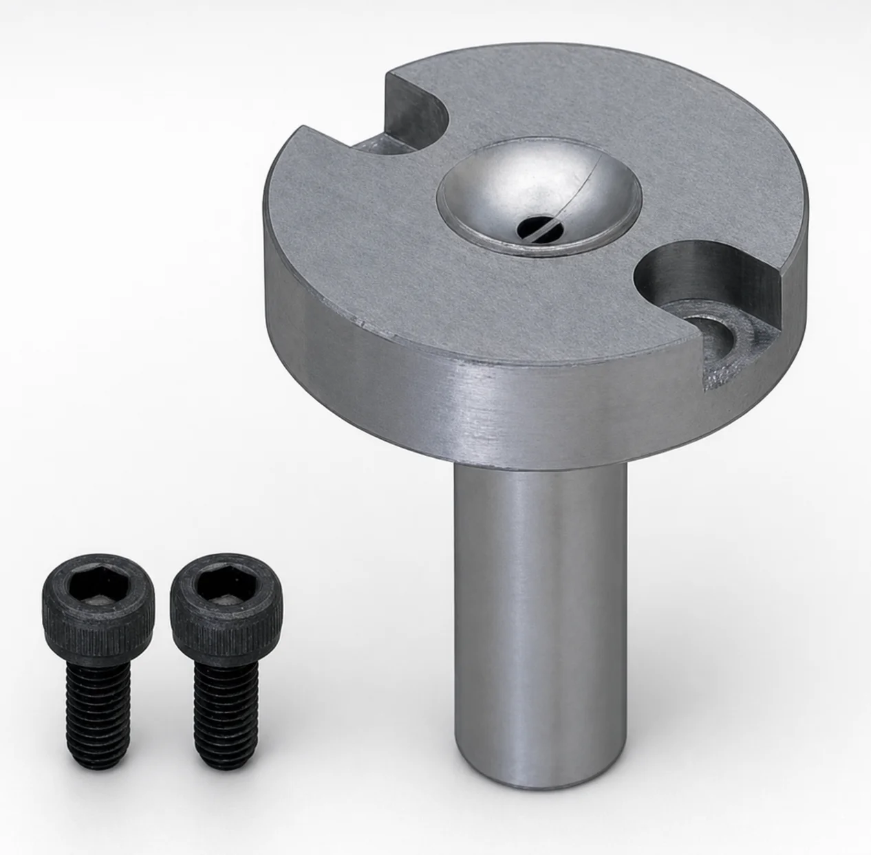
JIS Standard Steel Sprue Bushings - Bolt Fixing String Eliminator (Flange 10 mm)
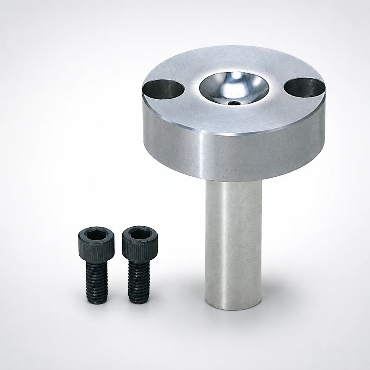
Sprue Bushings - Bolt Fixing Flange Thickness 15 mm
Need Custom Specifications?
Our engineering team can help with custom configurations, material selection, and volume pricing.