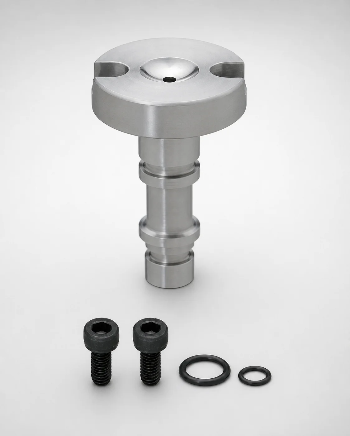
Sprue Bushings Cooling Circuit Flange Thickness 10 mm
Sprue bushings cooling circuit flange thickness 10 mm are designed to integrate into sprue systems around the cooling circuit, providing stable nozzle guidance and consistent melt flow control during molding. Straight tip matching supports reliable alignment on the sprue side.
- Cooling-circuit integrated bushing design for controlled nozzle positioning
- Material options include SKD61 or SUS420J2 equivalent for wear resistance
- Selectable hardness ranges up to 47–50 HRC for demanding production cycles
- Common nozzle interface options support normal contact or string eliminator configurations
Specifications
12 configurations available
| Material | Nozzle Touch Part Specification | D (Shaft Diameter) (mm) | L (Bearing bore length) (mm) | A (Taper angle at sprue) (°) | Hardness | CW (Groove width) (mm) | P (Sprue diameter) (mm) | SR (Nozzle part) (mm) | type |
|---|---|---|---|---|---|---|---|---|---|
| SKD61 | Normal | 16 | 40 ~ 100 | 0.5 ~ 2 | - | 6 ~ 40 | 2 ~ 3.5 | 10.5 ~ 20 | - |
| SKD61 | Normal | 20 | 40 ~ 150 | 0.5 ~ 3.5 | - | 6 ~ 40 | 2 ~ 4.5 | 10.5 ~ 20 | - |
| SKD61 | String eliminator | 16 | 40 ~ 100 | 0.5 ~ 2 | - | 6 ~ 40 | 2 ~ 3.5 | 10.5 ~ 20 | - |
| SKD61 | String eliminator | 20 | 40 ~ 150 | 0.5 ~ 3.5 | - | 6 ~ 40 | 2 ~ 4.5 | 10.5 ~ 20 | - |
| SUS420J2 Equivalent | Normal | 16 | 40 ~ 100 | 0.5 ~ 2 | 47~50HRC | 6 ~ 40 | 2 ~ 3.5 | 10.5 ~ 20 | - |
| SUS420J2 Equivalent | Normal | 20 | 40 ~ 150 | 0.5 ~ 3.5 | 47~50HRC | 6 ~ 40 | 2 ~ 4.5 | 10.5 ~ 20 | - |
| SUS420J2 Equivalent | String eliminator | 16 | 40 ~ 100 | 0.5 ~ 2 | 47~50HRC | 6 ~ 40 | 2 ~ 3.5 | 10.5 ~ 20 | - |
| SUS420J2 Equivalent | String eliminator | 20 | 40 ~ 150 | 0.5 ~ 3.5 | 47~50HRC | 6 ~ 40 | 2 ~ 4.5 | 10.5 ~ 20 | - |
| SUS420J2 Equivalent | Normal | 16 | 40 ~ 100 | 0.5 ~ 2 | 37~43HRC | 6 ~ 40 | 2 ~ 3.5 | 10.5 ~ 20 | - |
| SUS420J2 Equivalent | Normal | 20 | 40 ~ 150 | 0.5 ~ 3.5 | 37~43HRC | 6 ~ 40 | 2 ~ 4.5 | 10.5 ~ 20 | - |
| SUS420J2 Equivalent | String eliminator | 16 | 40 ~ 100 | 0.5 ~ 2 | 37~43HRC | 6 ~ 40 | 2 ~ 3.5 | 10.5 ~ 20 | - |
| SUS420J2 Equivalent | String eliminator | 20 | 40 ~ 150 | 0.5 ~ 3.5 | 37~43HRC | 6 ~ 40 | 2 ~ 4.5 | 10.5 ~ 20 | - |
Product Guide
Application Scenarios+
This sprue bushing flange is used in injection mold sprue assemblies where the cooling circuit must remain stable while supporting precise nozzle contact. Typical use cases include automotive connector molds, where repeated thermal cycling demands consistent melt flow and reliable alignment between nozzle and sprue side.
For consumer electronics housings and other thin-wall parts, the controlled nozzle positioning helps reduce variation in sprue temperature and can support repeatable packing behavior across high-cavity runs.
In medical device housings and assemblies requiring cleaner sprue conditions, the variant with a string eliminator nozzle touch part configuration is well suited to limit stringing at the interface. The provided material options (SKD61 or SUS420J2 equivalent) and hardness ranges support wear resistance under normal or stringent production cycles.
- Integrates around the cooling circuit flange to improve positional stability.
- Supports normal contact and string-eliminator nozzle interfaces for different sprue conditions.
- Material/hardness selections match long-run wear demands.
Material & Process Details+
Available steels are SKD61 and a SUS420J2 equivalent stainless option. SKD61 is commonly selected for hot-work and wear resistance performance, while the SUS420J2-equivalent material is chosen where corrosion resistance and surface durability are prioritized for sprue-side components.
Hardness is selectable in two ranges: 47–50 HRC for demanding production cycles, or 37–43 HRC when balancing toughness and machining relief is preferred. Higher hardness generally improves wear resistance at the nozzle contact region, but can reduce toughness under severe thermal shock if not matched to tool design and operating conditions.
Heat treatment is typically delivered in a hardened state suitable for bushing service; SKD61 parts are commonly supplied quenched and tempered to reach the requested HRC level, while the stainless variant is hardened to the specified hardness range for dimensional stability under repeated cycles.
- SKD61: higher wear resistance target (up to 47–50 HRC).
- SUS420J2 equivalent: stainless durability while maintaining the required hardness.
Sizing & Selection Guide+
Selection starts with matching the shaft diameter D and the overall bearing bore length L to the sprue-side geometry and support depth. This series is offered with D = 16 mm or 20 mm, and L = 40–100 mm or 40–150 mm depending on the configuration.
Next, align the taper angle A to the nozzle contact/conical sprue interface: options include 0.5–2° and 0.5–3.5°. The nozzle touch part specification must be selected as either Normal or String eliminator to suit the intended sprue condition.
Confirm interface geometry using the fixed and range parameters: SR (nozzle part) = 10.5–20 mm and CW (groove width) = 6–40 mm. The sprue diameter P must match your sprue assembly requirements (P = 2–3.5 mm or 2–4.5 mm), ensuring the bushing groove and nozzle contact region are sized for consistent melt flow.
- Choose D to fit the cooling circuit flange opening and guide bore.
- Choose L to provide adequate support length without over-interference.
- Verify A, P, SR, and CW against cavity/core sprue alignment features.
Frequently Asked Questions
Which material option should I choose for high-wear nozzle contact: SKD61 or SUS420J2 equivalent?+
How do I decide between Normal and String eliminator nozzle touch part specifications?+
What taper angle (A) range matches my conical sprue/nozzle interface?+
How should I select the shaft diameter D and bearing bore length L for correct fit in the mold?+
Is the hardness range (47–50 HRC vs 37–43 HRC) a trade-off I should consider for toughness?+
Related Products
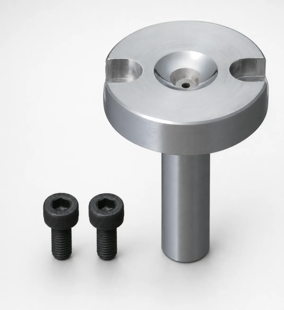
Bolt Fixing Sprue Bushings - Flange Thickness 10 mm
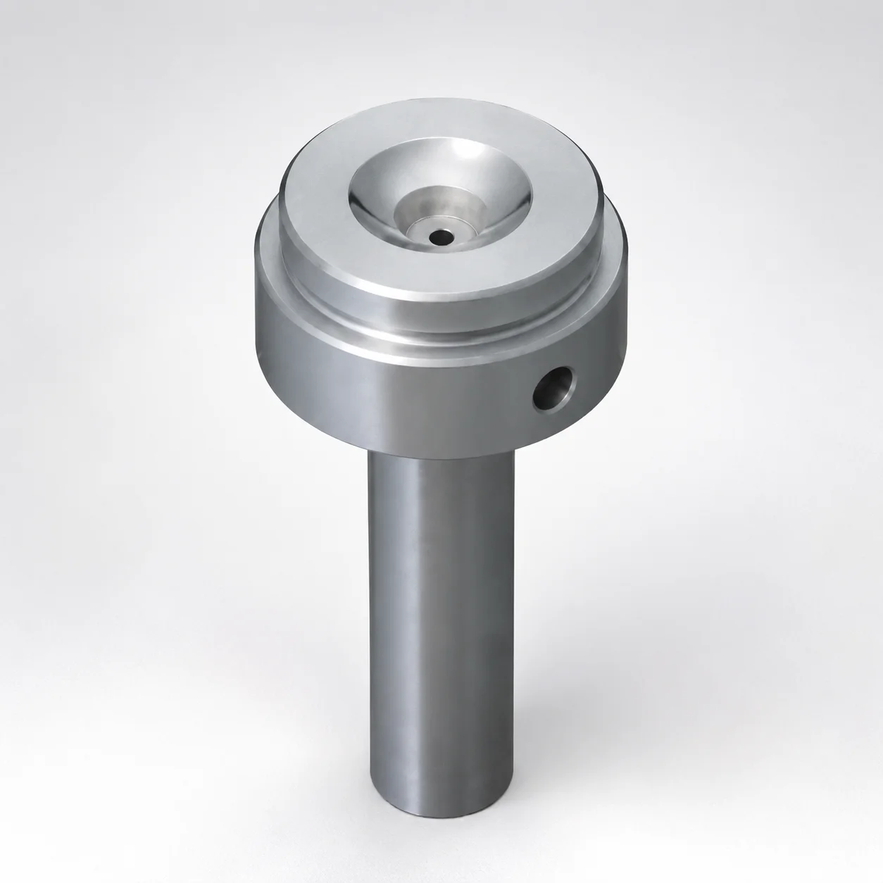
Sprue Bushings Shoulder Type - Flange Thickness 15 mm
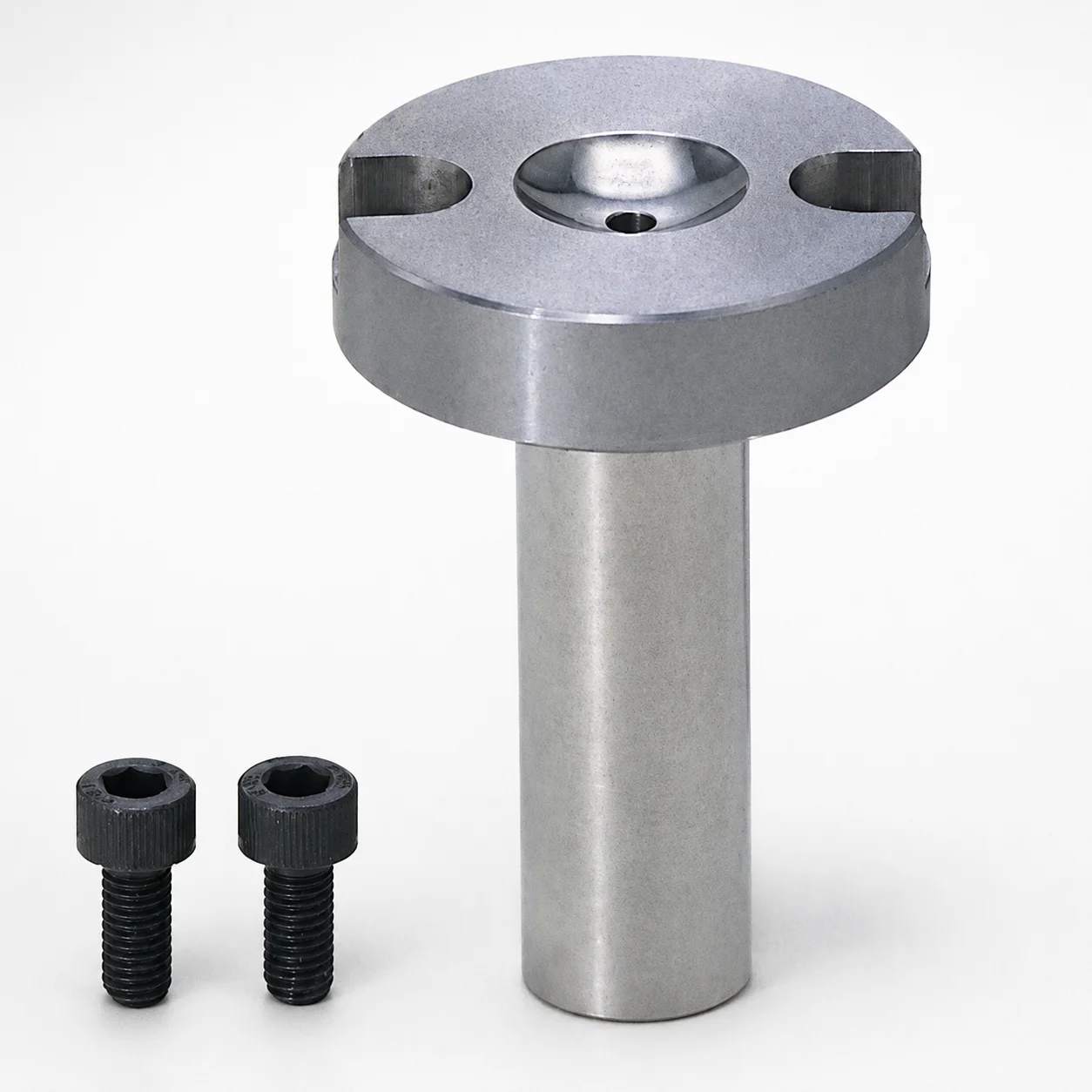
Sprue Bushings - Bolt Fixing Flange Thickness 10 mm
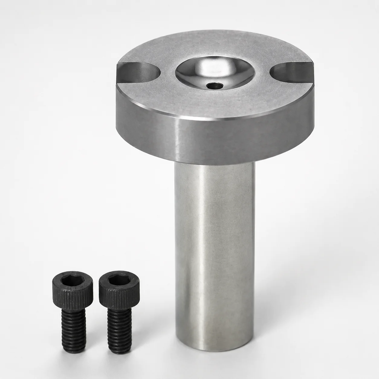
Sprue Bushings - Bolt Fixing, Flange Thickness 10 mm
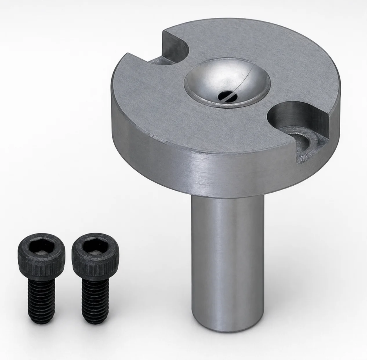
JIS Standard Steel Sprue Bushings - Bolt Fixing String Eliminator (Flange 10 mm)
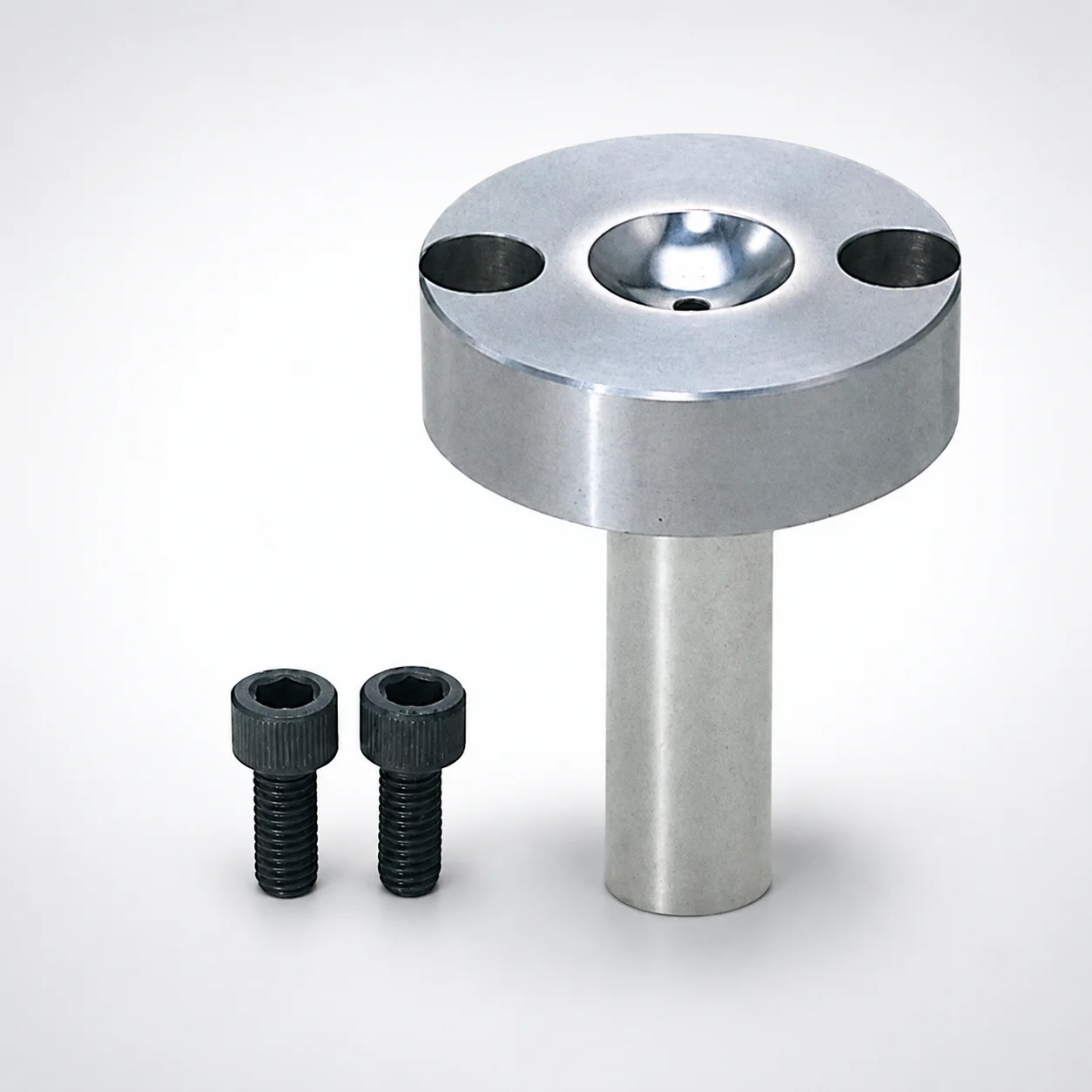
Sprue Bushings - Bolt Fixing Flange Thickness 15 mm
Need Custom Specifications?
Our engineering team can help with custom configurations, material selection, and volume pricing.