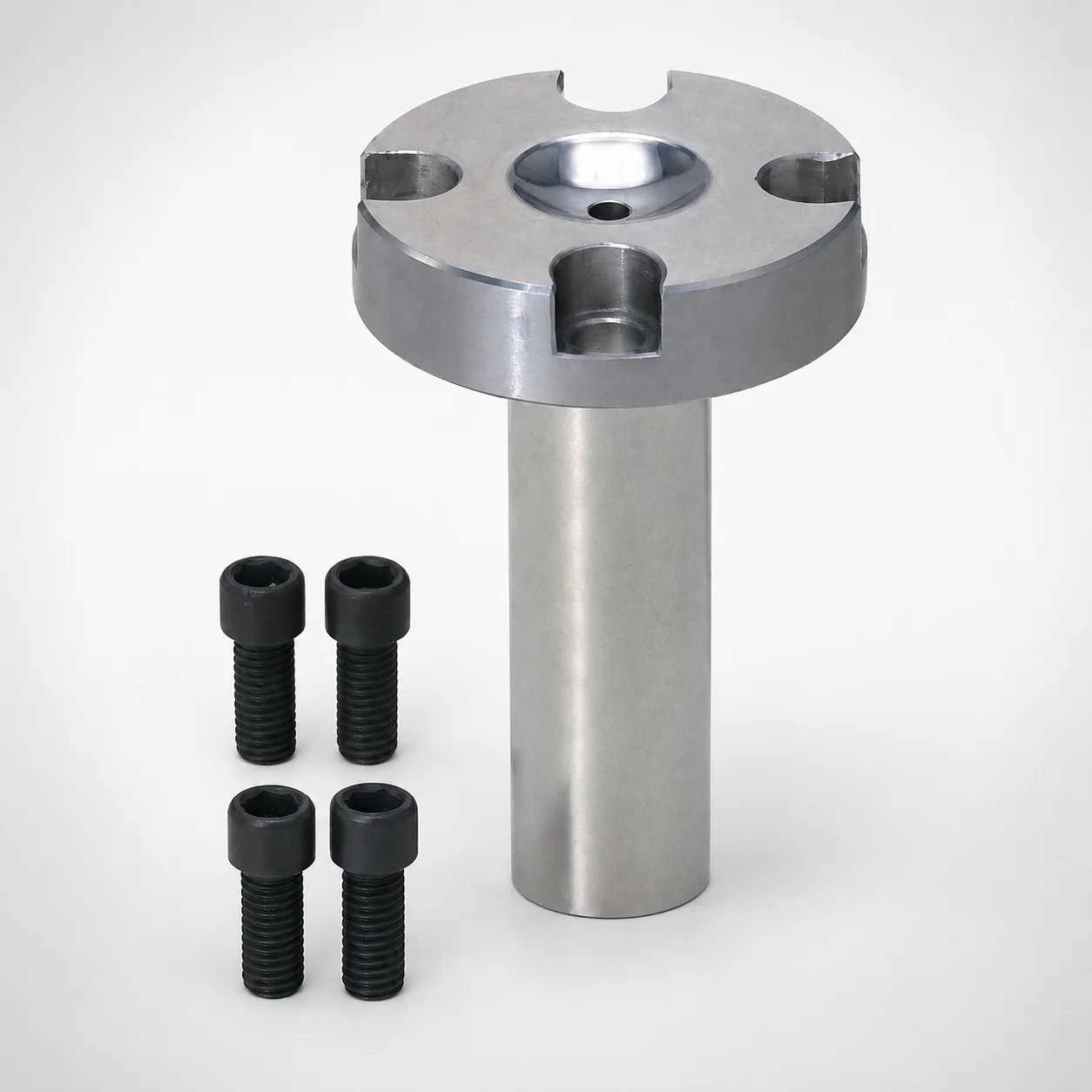
Sprue Bushings Bolt Fixing Flange Thickness 10 mm with Special Bolt
Sprue Bushings (Bolt Fixing) with a Flange Thickness 10 mm design and special bolt mounting provide stable sprue retention and consistent alignment during molding. Built for efficient installation on standard mold bases.
- Bolt fixing construction supports repeatable positioning of sprue tooling
- Flange thickness 10 mm flange-mount layout for straightforward mold integration
- Special bolt fastening helps maintain secure assembly under molding loads
- Suitable for injection molding systems requiring controlled nozzle-to-sprue interfaces
Specifications
60 configurations available
| Material | Tip Matching Shape | Nozzle Touch Part Specification | D (Shaft Diameter) (mm) | L (Bearing bore length) (mm) | A (Taper angle at sprue) (°) | F (Resin pocket depth) (mm) | G (Taper angle) (°) | P (Sprue diameter) (mm) | SR (Nozzle part) (mm) | V (Tip diameter) (mm) | type |
|---|---|---|---|---|---|---|---|---|---|---|---|
| SKD61 | Straight | Normal | 10 | 0 ~ 120 | 0.5 ~ 4 | - | - | 2 ~ 8 | 0 ~ 23 | - | - |
| SKD61 | Straight | Normal | 13 | 0 ~ 150 | 0.5 ~ 4 | - | - | 2 ~ 8 | 0 ~ 23 | - | - |
| SKD61 | Straight | Normal | 16 | 0 ~ 150 | 0.5 ~ 4 | - | - | 2 ~ 8 | 0 ~ 23 | - | - |
| SKD61 | Straight | Normal | 20 | 0 ~ 200 | 0.5 ~ 4 | - | - | 2 ~ 8 | 0 ~ 23 | - | - |
| SKD61 | Straight | Normal | 25 | 0 ~ 200 | 0.5 ~ 4 | - | - | 2 ~ 8 | 0 ~ 23 | - | - |
| SKD61 | Straight | Resin pocket | 10 | 0 ~ 120 | 0.5 ~ 4 | 0.3 ~ 2 | - | 2 ~ 8 | 10.5 ~ 11 | - | - |
| SKD61 | Straight | Resin pocket | 13 | 0 ~ 150 | 0.5 ~ 4 | 0.3 ~ 2 | - | 2 ~ 8 | 10.5 ~ 11 | - | - |
| SKD61 | Straight | Resin pocket | 16 | 0 ~ 150 | 0.5 ~ 4 | 0.3 ~ 2 | - | 2 ~ 8 | 10.5 ~ 11 | - | - |
| SKD61 | Straight | Resin pocket | 20 | 0 ~ 200 | 0.5 ~ 4 | 0.3 ~ 2 | - | 2 ~ 8 | 10.5 ~ 11 | - | - |
| SKD61 | Straight | Resin pocket | 25 | 0 ~ 200 | 0.5 ~ 4 | 0.3 ~ 2 | - | 2 ~ 8 | 10.5 ~ 11 | - | - |
| SKD61 | Straight | String eliminator | 10 | 0 ~ 120 | 0.5 ~ 4 | - | - | 2 ~ 8 | 0 ~ 16 | - | - |
| SKD61 | Straight | String eliminator | 13 | 0 ~ 150 | 0.5 ~ 4 | - | - | 2 ~ 8 | 0 ~ 16 | - | - |
| SKD61 | Straight | String eliminator | 16 | 0 ~ 150 | 0.5 ~ 4 | - | - | 2 ~ 8 | 0 ~ 16 | - | - |
| SKD61 | Straight | String eliminator | 20 | 0 ~ 200 | 0.5 ~ 4 | - | - | 2 ~ 8 | 0 ~ 16 | - | - |
| SKD61 | Straight | String eliminator | 25 | 0 ~ 200 | 0.5 ~ 4 | - | - | 2 ~ 8 | 0 ~ 16 | - | - |
| HPM1 Equivalent | Straight | Normal | 10 | 0 ~ 120 | 0.5 ~ 4 | - | - | 2 ~ 8 | 0 ~ 23 | - | - |
| HPM1 Equivalent | Straight | Normal | 13 | 0 ~ 150 | 0.5 ~ 4 | - | - | 2 ~ 8 | 0 ~ 23 | - | - |
| HPM1 Equivalent | Straight | Normal | 16 | 0 ~ 150 | 0.5 ~ 4 | - | - | 2 ~ 8 | 0 ~ 23 | - | - |
| HPM1 Equivalent | Straight | Normal | 20 | 0 ~ 200 | 0.5 ~ 4 | - | - | 2 ~ 8 | 0 ~ 23 | - | - |
| HPM1 Equivalent | Straight | Normal | 25 | 0 ~ 200 | 0.5 ~ 4 | - | - | 2 ~ 8 | 0 ~ 23 | - | - |
| HPM1 Equivalent | Straight | Resin pocket | 10 | 0 ~ 120 | 0.5 ~ 4 | 0.3 ~ 2 | - | 2 ~ 8 | 10.5 ~ 11 | - | - |
| HPM1 Equivalent | Straight | Resin pocket | 13 | 0 ~ 150 | 0.5 ~ 4 | 0.3 ~ 2 | - | 2 ~ 8 | 10.5 ~ 11 | - | - |
| HPM1 Equivalent | Straight | Resin pocket | 16 | 0 ~ 150 | 0.5 ~ 4 | 0.3 ~ 2 | - | 2 ~ 8 | 10.5 ~ 11 | - | - |
| HPM1 Equivalent | Straight | Resin pocket | 20 | 0 ~ 200 | 0.5 ~ 4 | 0.3 ~ 2 | - | 2 ~ 8 | 10.5 ~ 11 | - | - |
| HPM1 Equivalent | Straight | Resin pocket | 25 | 0 ~ 200 | 0.5 ~ 4 | 0.3 ~ 2 | - | 2 ~ 8 | 10.5 ~ 11 | - | - |
| HPM1 Equivalent | Straight | String eliminator | 10 | 0 ~ 100 | 0.5 ~ 4 | - | - | 2.5 ~ 8 | 0 ~ 16 | - | - |
| HPM1 Equivalent | Straight | String eliminator | 13 | 0 ~ 100 | 0.5 ~ 4 | - | - | 2.5 ~ 8 | 0 ~ 16 | - | - |
| HPM1 Equivalent | Straight | String eliminator | 16 | 0 ~ 150 | 0.5 ~ 4 | - | - | 2.5 ~ 8 | 0 ~ 16 | - | - |
| HPM1 Equivalent | Straight | String eliminator | 20 | 0 ~ 200 | 0.5 ~ 4 | - | - | 2.5 ~ 8 | 0 ~ 16 | - | - |
| HPM1 Equivalent | Straight | String eliminator | 25 | 0 ~ 150 | 0.5 ~ 4 | - | - | 2.5 ~ 8 | 0 ~ 16 | - | - |
| SKD61 | Tapered | Normal | 10 | 0 ~ 120 | 0.5 ~ 4 | - | 1 ~ 10 | 2 ~ 8 | 0 ~ 23 | 4 ~ 9.9 | - |
| SKD61 | Tapered | Normal | 13 | 0 ~ 150 | 0.5 ~ 4 | - | 1 ~ 10 | 2 ~ 8 | 0 ~ 23 | 4 ~ 12.9 | - |
| SKD61 | Tapered | Normal | 16 | 0 ~ 150 | 0.5 ~ 4 | - | 1 ~ 10 | 2 ~ 8 | 0 ~ 23 | 4 ~ 15.9 | - |
| SKD61 | Tapered | Normal | 20 | 0 ~ 200 | 0.5 ~ 4 | - | 1 ~ 10 | 2 ~ 8 | 0 ~ 23 | 4 ~ 19.9 | - |
| SKD61 | Tapered | Normal | 25 | 0 ~ 200 | 0.5 ~ 4 | - | 1 ~ 10 | 2 ~ 8 | 0 ~ 23 | 4 ~ 24.9 | - |
| SKD61 | Tapered | Resin pocket | 10 | 0 ~ 120 | 0.5 ~ 4 | 0.3 ~ 2 | 1 ~ 10 | 2 ~ 8 | 10.5 ~ 11 | 4 ~ 9.9 | - |
| SKD61 | Tapered | Resin pocket | 13 | 0 ~ 150 | 0.5 ~ 4 | 0.3 ~ 2 | 1 ~ 10 | 2 ~ 8 | 10.5 ~ 11 | 4 ~ 12.9 | - |
| SKD61 | Tapered | Resin pocket | 16 | 0 ~ 150 | 0.5 ~ 4 | 0.3 ~ 2 | 1 ~ 10 | 2 ~ 8 | 10.5 ~ 11 | 4 ~ 15.9 | - |
| SKD61 | Tapered | Resin pocket | 20 | 0 ~ 200 | 0.5 ~ 4 | 0.3 ~ 2 | 1 ~ 10 | 2 ~ 8 | 10.5 ~ 11 | 4 ~ 19.9 | - |
| SKD61 | Tapered | Resin pocket | 25 | 0 ~ 200 | 0.5 ~ 4 | 0.3 ~ 2 | 1 ~ 10 | 2 ~ 8 | 10.5 ~ 11 | 4 ~ 24.9 | - |
| SKD61 | Tapered | String eliminator | 10 | 0 ~ 120 | 0.5 ~ 4 | - | 1 ~ 10 | 2.5 ~ 8 | 0 ~ 16 | 4 ~ 9.9 | - |
| SKD61 | Tapered | String eliminator | 13 | 0 ~ 150 | 0.5 ~ 4 | - | 1 ~ 10 | 2.5 ~ 8 | 0 ~ 16 | 4 ~ 12.9 | - |
| SKD61 | Tapered | String eliminator | 16 | 0 ~ 150 | 0.5 ~ 4 | - | 1 ~ 10 | 2.5 ~ 8 | 0 ~ 16 | 4 ~ 15.9 | - |
| SKD61 | Tapered | String eliminator | 20 | 0 ~ 200 | 0.5 ~ 4 | - | 1 ~ 10 | 2.5 ~ 8 | 0 ~ 16 | 4 ~ 19.9 | - |
| SKD61 | Tapered | String eliminator | 25 | 0 ~ 200 | 0.5 ~ 4 | - | 1 ~ 10 | 2.5 ~ 8 | 0 ~ 16 | 4 ~ 24.9 | - |
| HPM1 Equivalent | Tapered | Normal | 10 | 0 ~ 100 | 0.5 ~ 4 | - | 1 ~ 10 | 2 ~ 8 | 0 ~ 23 | 4 ~ 9.9 | - |
| HPM1 Equivalent | Tapered | Normal | 13 | 0 ~ 100 | 0.5 ~ 4 | - | 1 ~ 10 | 2 ~ 8 | 0 ~ 23 | 4 ~ 12.9 | - |
| HPM1 Equivalent | Tapered | Normal | 16 | 0 ~ 150 | 0.5 ~ 4 | - | 1 ~ 10 | 2 ~ 8 | 0 ~ 23 | 4 ~ 15.9 | - |
| HPM1 Equivalent | Tapered | Normal | 20 | 0 ~ 200 | 0.5 ~ 4 | - | 1 ~ 10 | 2 ~ 8 | 0 ~ 23 | 4 ~ 19.9 | - |
| HPM1 Equivalent | Tapered | Normal | 25 | 0 ~ 200 | 0.5 ~ 4 | - | 1 ~ 10 | 2 ~ 8 | 0 ~ 23 | 4 ~ 24.9 | - |
Product Guide
Application Scenarios+
Sprue bushings with bolt fixing are used to lock the sprue/nozzle interface inside injection mold tooling so that sprue alignment remains stable across repeated cycles. The 10 mm flange thickness flange-mount design is well suited for mold bases where a rigid, repeatable bolted location is required for consistent centering and mating.
- For automotive connector and housing molds, the secure bolt fastening helps maintain nozzle-to-sprue positioning under higher injection pressures, reducing risks of flash at the interface.
- For industrial appliance parts, selecting straight or tapered tip matching and the appropriate nozzle touch part specification (normal / resin pocket / string eliminator) supports stable flow control and reduces stringing.
- For precision thin-wall products, using the correct sprue diameter and taper angles (A and G ranges) supports controlled sprue formation, improving part-to-part reproducibility.
This variant’s flange-mount geometry and special bolt mounting provide reliable installation on standard mold bases, helping maintain repeatable alignment during molding loads.
Material & Process Details+
The bushing is available in SKD61 or HPM1-equivalentAISI H13, offering a balance of hot-work performance, toughness, and wear resistance for molding components exposed to heat and cycle stress.
- Wear resistance vs. toughness: These steels generally provide strong resistance to abrasive wear at the nozzle contact zone, while still maintaining useful impact toughness for everyday injection molding service.
- Typical heat treatment: For SKD61-type grades, components are typically quenched and tempered after machining to reach a working hardness suitable for repeated thermal cycling. (Hardness in HRC depends on the supplier’s final temper condition; confirm the delivered hardness for your project requirements.)
- Manufacturing process: Machining to achieve the specified taper and pocket geometry is followed by heat treatment to stabilize dimensions and improve service life.
If you require higher abrasion tolerance at the tip, SKD61/HPM1-equivalent is commonly selected; if your application emphasizes dimensional stability and general toughness, the tempered condition remains the key lever.
Sizing & Selection Guide+
Select the sprue bushing size by matching the shaft diameter (D), the bearing bore length (L), and the nozzle-to-sprue geometry requirements for your mold design.
- Choose D (shaft diameter): Available options are 10, 13, 16, 20, 25 mm. Use the D that matches the diameter of the receiving cavity/core bore and the mold base’s mounting interface.
- Choose L (bearing bore length): Select from the provided ranges, such as 0–120, 0–150, 0–200, or 0–100 mm, to achieve proper engagement depth without bottoming.
- Match sprue and tip geometry: Set P (sprue diameter) within 2–8 mm (or 2.5–8 mm depending on the variant), then select Tip matching shape (straight or tapered) and V (tip diameter) in the available ranges (4–9.9, 4–12.9, 4–15.9, 4–19.9, 4–24.9 mm).
- Taper and pocket control: Confirm A (0.5–4°), G (1–10°), and F (resin pocket depth, 0.3–2 mm) against your nozzle touch part type (normal / resin pocket / string eliminator).
When integrating into injection mold tooling, ensure clearance for thermal expansion and verify that the installed flange-mount face seats properly. Dimensional tolerances are not provided here; validate fit against your mold base tolerances and inspection drawings.
Frequently Asked Questions
Which sprue bushing size should I select for a given nozzle-to-sprue interface—how do D and P work together?+
Start with D (shaft diameter) because it determines the mechanical fit in the mold base: available D values are 10, 13, 16, 20, 25 mm. Then match the sprue diameter P within the provided ranges (e.g., 2–8 mm or 2.5–8 mm) to ensure correct flow cross-section at the interface. After that, verify taper settings (A 0.5–4°, G 1–10°) and the tip matching style (straight/tapered) for consistent seating.
For nozzle touch parts like resin pocket or string eliminator, which parameters control pocket depth and tip geometry?+
When your nozzle touch part is specified as resin pocket or string eliminator, focus on the bushing’s pocket and taper geometry. The F resin pocket depth is specified as 0.3–2 mm, and the taper angles are A (0.5–4°) and G (1–10°). Also select the appropriate Tip matching shape (straight or tapered) and confirm V (tip diameter) within the available ranges.
How do I choose the bearing bore length L to avoid under-engagement or interference?+
Pick L (bearing bore length) based on the required engagement depth in your mold base design. Available options are provided as ranges such as 0–120, 0–150, 0–200, or 0–100 mm. Select an L that lets the flange-mount face seat correctly and ensures the internal bore length supports stable alignment without bottoming or creating interference at cycle temperatures.
Is SKD61 or HPM1-equivalent the better choice for sprue bushing wear at the nozzle contact zone?+
This product is offered in SKD61 (H13-equivalent) or HPM1-equivalent tool steel. Both are designed for hot/cycle service and generally provide a good balance of wear resistance and toughness when properly heat-treated. For nozzle contact wear, the deciding factor is typically the delivered hardness and tempered condition; confirm the final HRC and treatment state for your specific order.
How do taper angles A and G affect assembly alignment and sprue formation?+
A (taper angle at sprue) is specified as 0.5–4°, while G is specified as 1–10°. Together, these angles define how the tip seats against the nozzle touch surface and influence sprue formation consistency. For best results, match A and G to your nozzle’s mating geometry and then select the appropriate tip matching shape (straight or tapered) and V within the required range.
Related Products
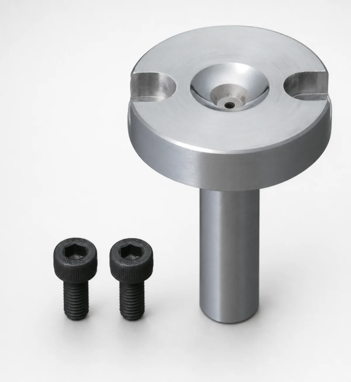
Bolt Fixing Sprue Bushings - Flange Thickness 10 mm
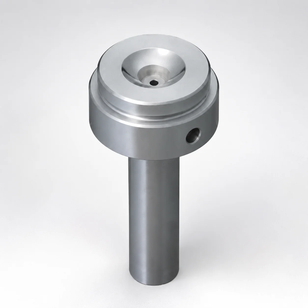
Sprue Bushings Shoulder Type - Flange Thickness 15 mm
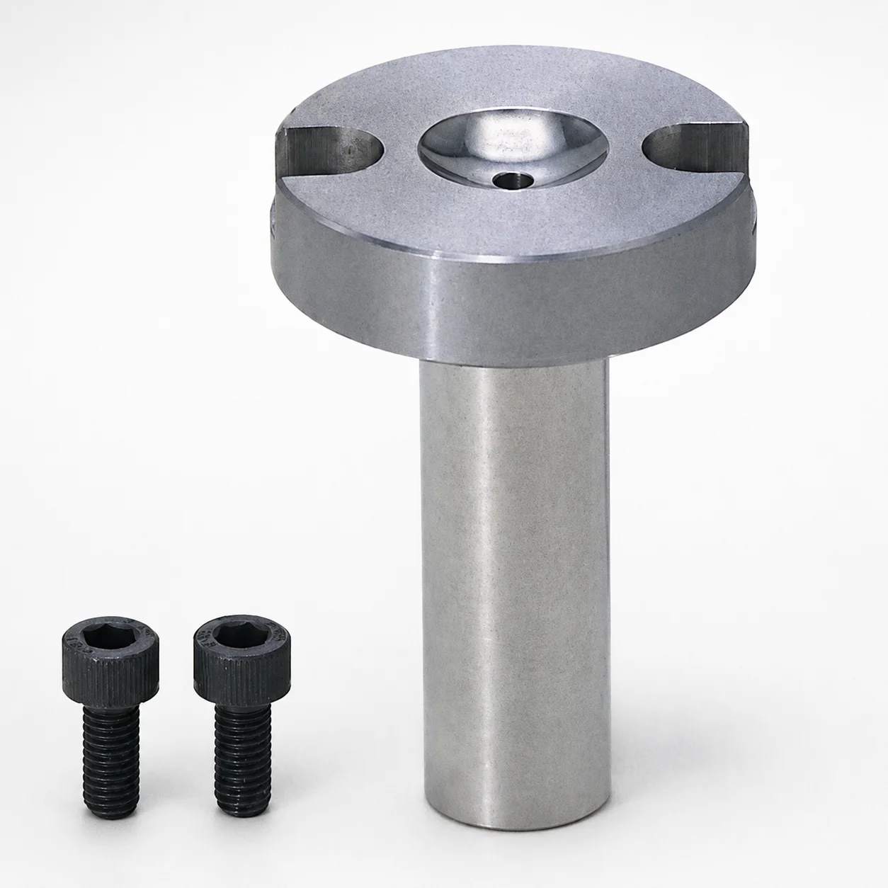
Sprue Bushings - Bolt Fixing Flange Thickness 10 mm
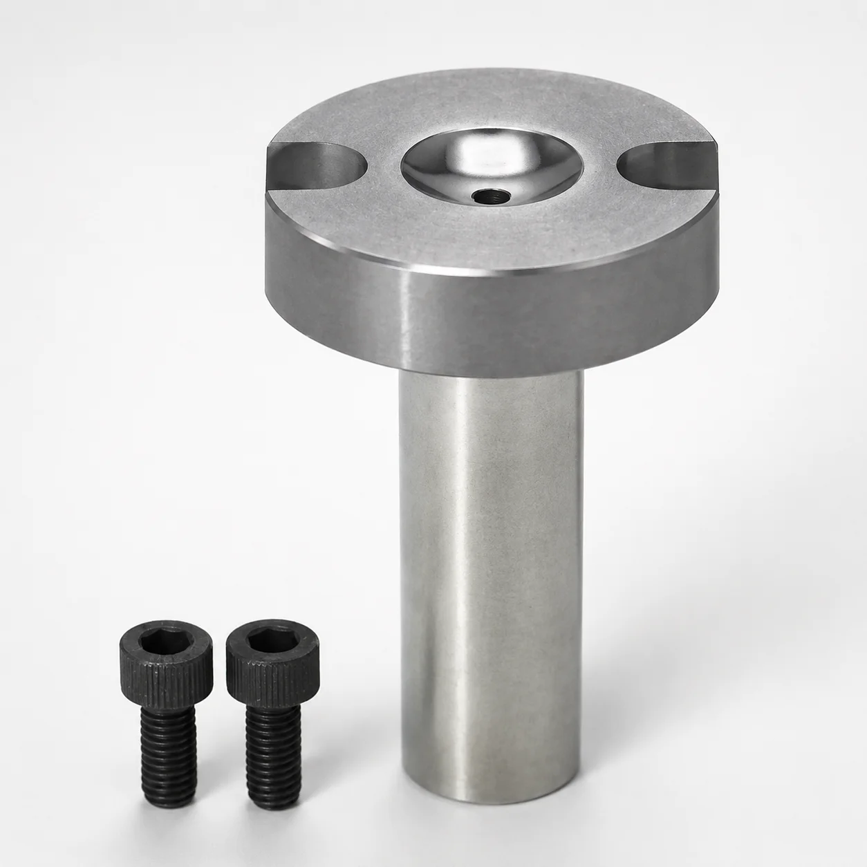
Sprue Bushings - Bolt Fixing, Flange Thickness 10 mm
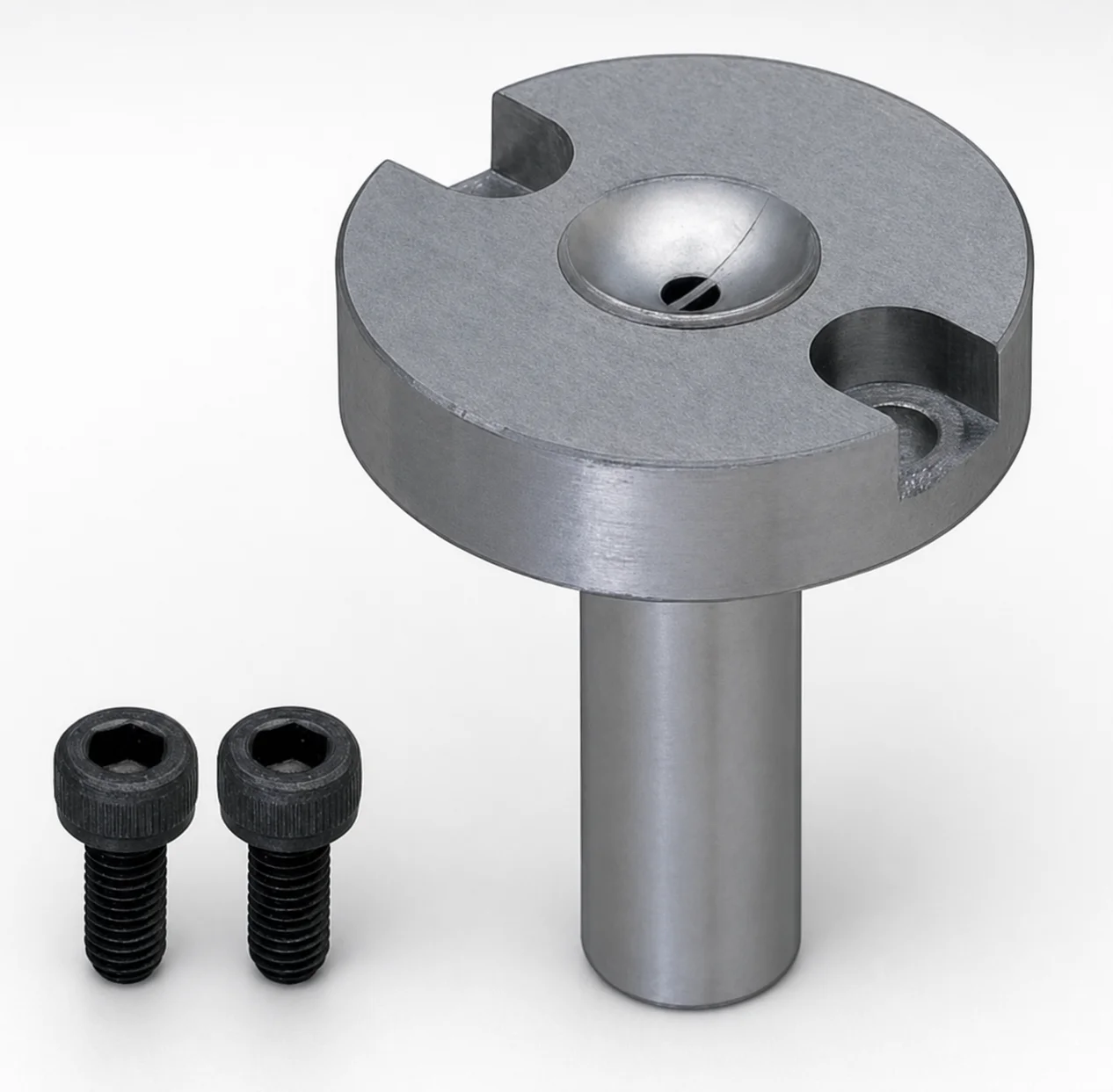
JIS Standard Steel Sprue Bushings - Bolt Fixing String Eliminator (Flange 10 mm)
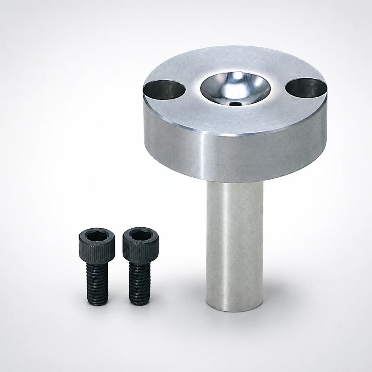
Sprue Bushings - Bolt Fixing Flange Thickness 15 mm
Need Custom Specifications?
Our engineering team can help with custom configurations, material selection, and volume pricing.