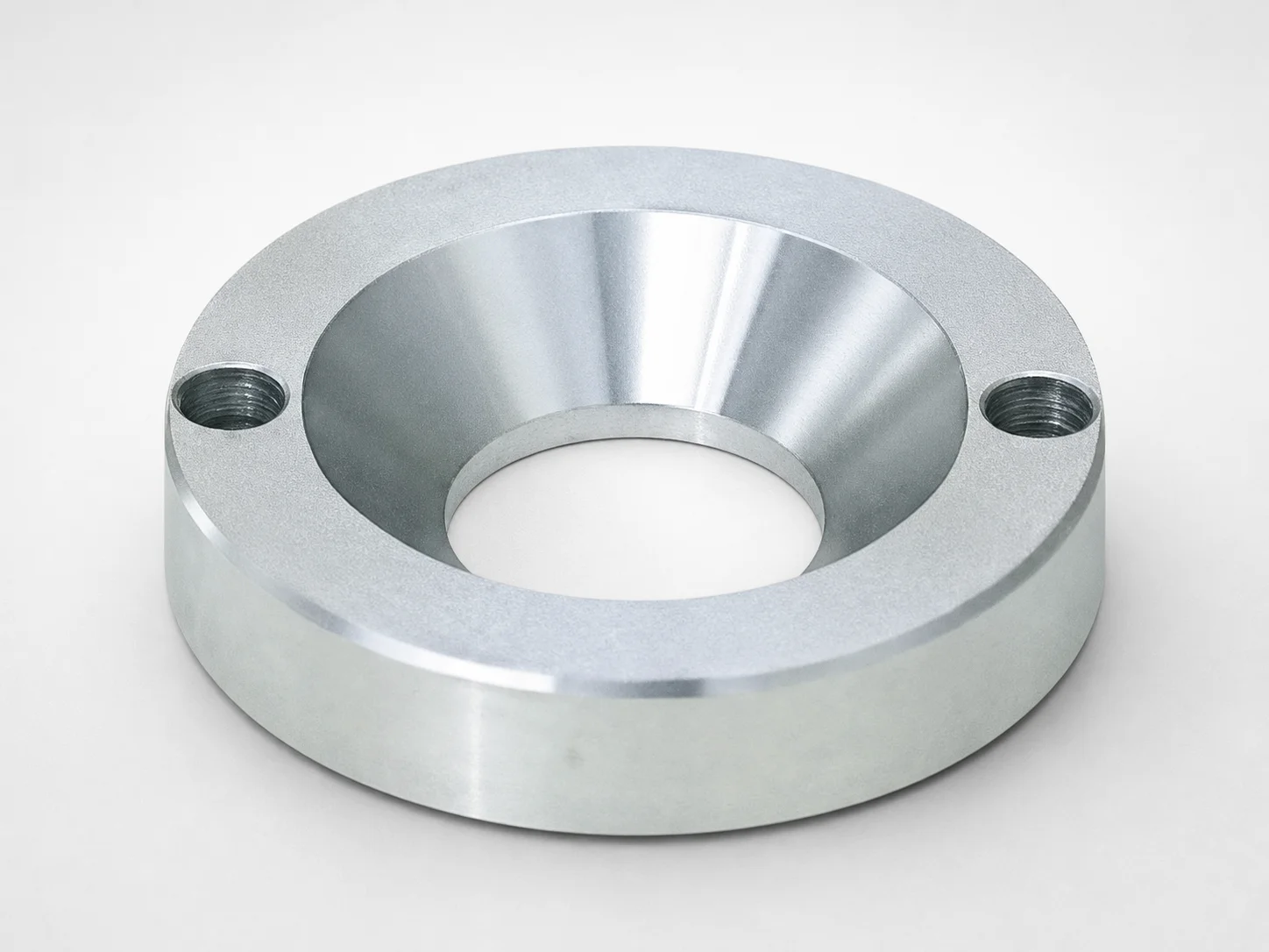
JIS Standard LRJS Locating Rings, Countersink, 2-Bolt Holes
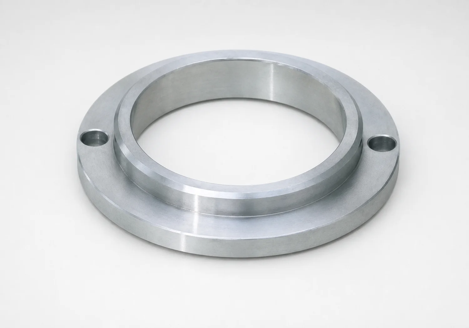
JIS Standard LRJS locating rings, countersink, 2-bolt holes are engineered for reliable part alignment in mold base locating systems. The JIS type geometry supports consistent positioning for production setups.
- JIS type locating ring for stable, repeatable alignment during operation
- Countersink style helps secure fastener seating for consistent assembly
- LRJS two-bolt arrangement improves positional stability under load
- Compatible with both bolt type and shoulder type sprue applications
Specifications
14 configurations available
| D (Locating Ring Outer Diameter) (mm) | T (Height) (mm) | B (Inner diameter) (mm) | type |
|---|---|---|---|
| 100 | 15 | 35 | - |
| 100 | 15 | 40 | - |
| 100 | 15 | 50 | - |
| 100 | 20 | 35 | - |
| 100 | 20 | 40 | - |
| 100 | 20 | 50 | - |
| 100 | 25 | 35 | - |
| 100 | 25 | 40 | - |
| 120 | 15 | 40 | - |
| 120 | 15 | 50 | - |
| 120 | 20 | 40 | - |
| 120 | 20 | 50 | - |
| 150 | 15 | 50 | - |
| 150 | 20 | 50 | - |
Product Guide
Application Scenarios+
These JIS LRJS locating rings are used in injection mold base locating systems where repeatable alignment is critical for maintaining gate and runner geometry. The countersink feature supports consistent fastener seating, helping reduce assembly variability across production setups.
- Automotive and appliance gate/runner tooling: The two-bolt (2-bolt holes) arrangement improves positional stability under clamp/load, which helps keep sprue and locating features aligned during cyclic operation.
- Multi-cavity molds with interchangeable base plates: Outer diameter (D) and height (T) combinations enable quick matching to existing locating pockets for faster changeovers while preserving registration.
- Sprue bushing and locating systems: The inner diameter (B) supports integration with bolt/shoulder locating architectures, improving concentricity for consistent part ejection and flow path positioning.
Choose the variant that matches your cavity/core locating pocket dimensions to ensure stable, repeatable positioning throughout the molding cycle.
Material & Process Details+
The provided specifications for this JIS Standard LRJS locating ring series focus on geometry (D, T, B) and hole layout, not on steel grade or heat treatment state. As a result, material properties such as hardness (HRC), wear resistance, and toughness trade-offs cannot be stated from the supplied data.
For locating rings used in high-cycle mold bases, typical engineering practice is to select wear-resistant, shock-tolerant mold steels and then apply appropriate heat treatment (for example, quench & temper for general durability, or nitriding for enhanced surface wear resistance). Actual material grade and treatment must be confirmed for this exact MISUMI series before specifying for your load, speed, and maintenance interval.
- Note: This page content is geometry-driven; verify steel grade before final design sign-off.
Sizing & Selection Guide+
Select dimensions by matching the locating ring to the corresponding mold base locating pocket and registration features. Use the available ranges: D (outer diameter) = 100, 120, or 150 mm; T (height) = 15, 20, or 25 mm; and B (inner diameter) = 35, 40, or 50 mm.
- Match D to the pocket OD/locator clearance: The outer diameter should fit the locating area geometry to prevent lateral shift and maintain repeatable alignment.
- Match T to the pocket depth/stack height: Height must align with your mold base thickness and any spacer/layer stack so the ring seats fully without over-compression.
- Match B to your locating hardware architecture: Inner diameter should correspond to the locating bolt/shoulder arrangement and surrounding clearance requirements to ensure smooth assembly.
- Tolerance/fit: Because tolerance values are not provided in the input data, confirm the target clearance/fit with your locating pocket drawings (especially for the countersink seating and 2-bolt hole registration).
Dimensions are configurable within the given D/T/B combinations; hole layout is fixed to the LRJS two-bolt geometry.
Frequently Asked Questions
Which LRJS locating ring dimensions (D, T, B) should I choose to match an existing mold base locating pocket?+
How does the LRJS two-bolt (2-bolt holes) layout affect stability in clamp/load conditions?+
What is the purpose of the countersink in this locating ring, and how should it influence assembly design?+
Is this LRJS locating ring intended for bolt-type or shoulder-type sprue applications?+
Can I specify hardness (HRC) and heat treatment for this locating ring from the provided data?+
Related Products
Need Custom Specifications?
Our engineering team can help with custom configurations, material selection, and volume pricing.