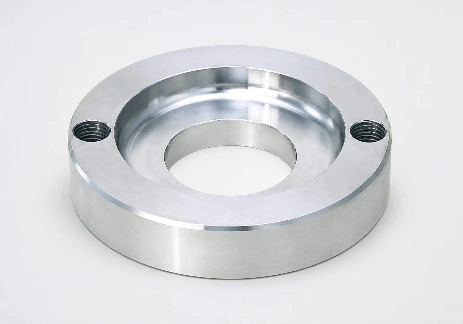
LRBD Locating Rings - Counterbore, 2-Bolt Holes
LRBD locating rings - counterbore, 2-bolt holes are designed for stable mold alignment using a standard locating ring type with a bolt stopper style interface. The counterbore configuration supports reliable positioning during assembly and operation.
- Counterbore design for accurate seating and repeatable alignment
- 2-bolt holes with bolt stopper type helps prevent positional shift
- LRBD ring type offers consistent locating performance across tooling
- Used in mold bases and locating systems where secure bolt-based alignment is required
Specifications
10 configurations available
| D (Locating Ring Outer Diameter) (mm) | T (Height) (mm) | type |
|---|---|---|
| 100 | 15 | - |
| 100 | 20 | - |
| 100 | 35 | - |
| 100 | 40 | - |
| 100 | 45 | - |
| 120 | 15 | - |
| 120 | 20 | - |
| 120 | 35 | - |
| 120 | 40 | - |
| 120 | 45 | - |
Product Guide
Application Scenarios+
This counterbore locating ring is used inside injection mold bases and locating systems to maintain repeatable part-to-part alignment during assembly and press operation. The 2-bolt holes are intended for a bolt stopper type interface, which helps resist micro-movements that can lead to mismatch in gate and sprue regions.
In automotive connector and cable-housing molds, the ring’s counterbore seats the hardware consistently, supporting stable alignment of mating mold halves when tightening bolts through the 2-hole pattern. In precision consumer electronics enclosure molds, where thin-walled inserts and tight shut-offs demand consistent positioning, the available heights (15–45 mm) allow designers to match required stack-up and clearance.
- Counterbore promotes accurate seating and repeatable alignment
- 2-bolt stopper interface reduces positional shift under clamping loads
- Multiple height options support tooling stack-up requirements
Material & Process Details+
The provided specifications for this LRBD locating ring define functional geometry (outer diameter D and height T) but do not state the steel grade, heat treatment, or hardness. Therefore, material hardness (HRC), wear resistance, and toughness trade-offs cannot be confirmed from the available data.
When sourcing locating hardware for injection tooling, engineers typically select steels based on expected clamp load cycles and alignment-critical wear characteristics (e.g., resisting fretting around bolt-stopper interfaces). If you need a specific grade (such as a nitriding-ready alloy) or a specified hardness range, request the material and heat-treatment certificate associated with series 110200080250.
- Material/heat treatment details not provided in current spec set
- Confirm hardness and surface treatment requirements before qualification
- Validate fit and wear behavior at the bolt-stopper contact surfaces
Sizing & Selection Guide+
Selection is driven by matching the locating ring outer diameter D and the mounting stack height T to the mold base and locating system geometry. This series is available with D = 100 or 120 mm and T = 15, 20, 35, 40, or 45 mm.
To size the ring, first determine the required seating diameter and clearance envelope in the mold base. Choose D so the counterbore lands within the intended seat location without interfering with adjacent features (ejector pockets, gate components, or bolt/stopper elements). Next, set T to match the required height for proper engagement of the bolt stopper interface after assembly.
- Match D (100/120 mm) to the counterbore seat zone
- Match T (15–45 mm) to your tooling stack-up
- Use the 2-bolt hole pattern consistently with the bolt stopper location hardware
Tolerance/fit note: the current data does not provide numeric tolerance values for D, T, or hole features—verify drawing tolerances during final design freeze.
Frequently Asked Questions
Which outer diameter D options are available for LRBD locating rings with counterbore?+
What height T values can be selected to match mold stack-up for the 2-bolt locating interface?+
Does the counterbore geometry affect seating repeatability in the locating system?+
How should the ring be matched to the mold’s bolt stopper type alignment features?+
What material grade and heat treatment are specified for series 110200080250?+
Related Products
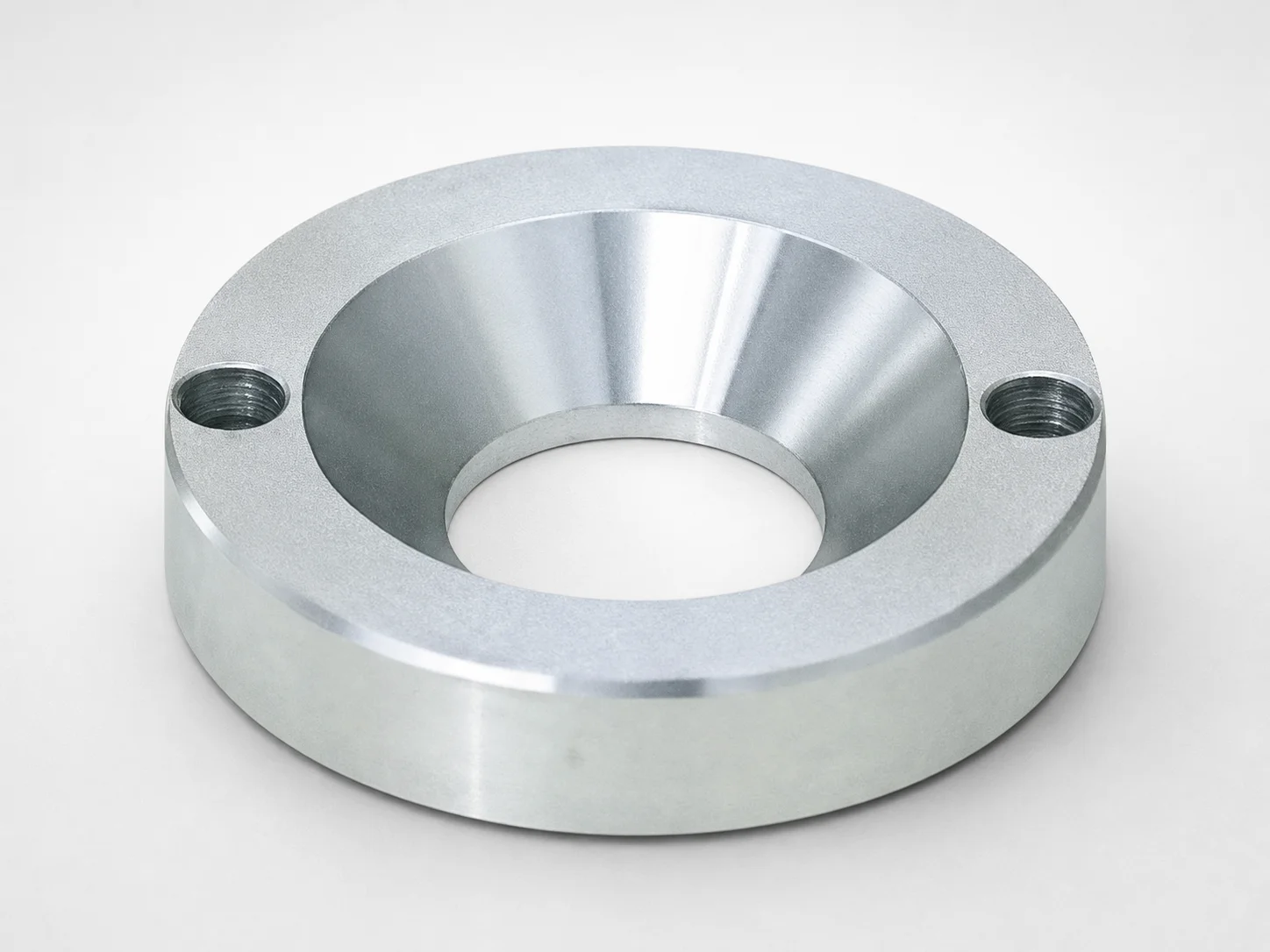
JIS Standard LRJS Locating Rings, Countersink, 2-Bolt Holes
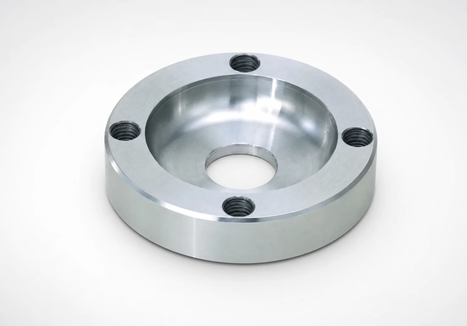
LRSS Locating Rings Counterbore 4-Bolt Holes
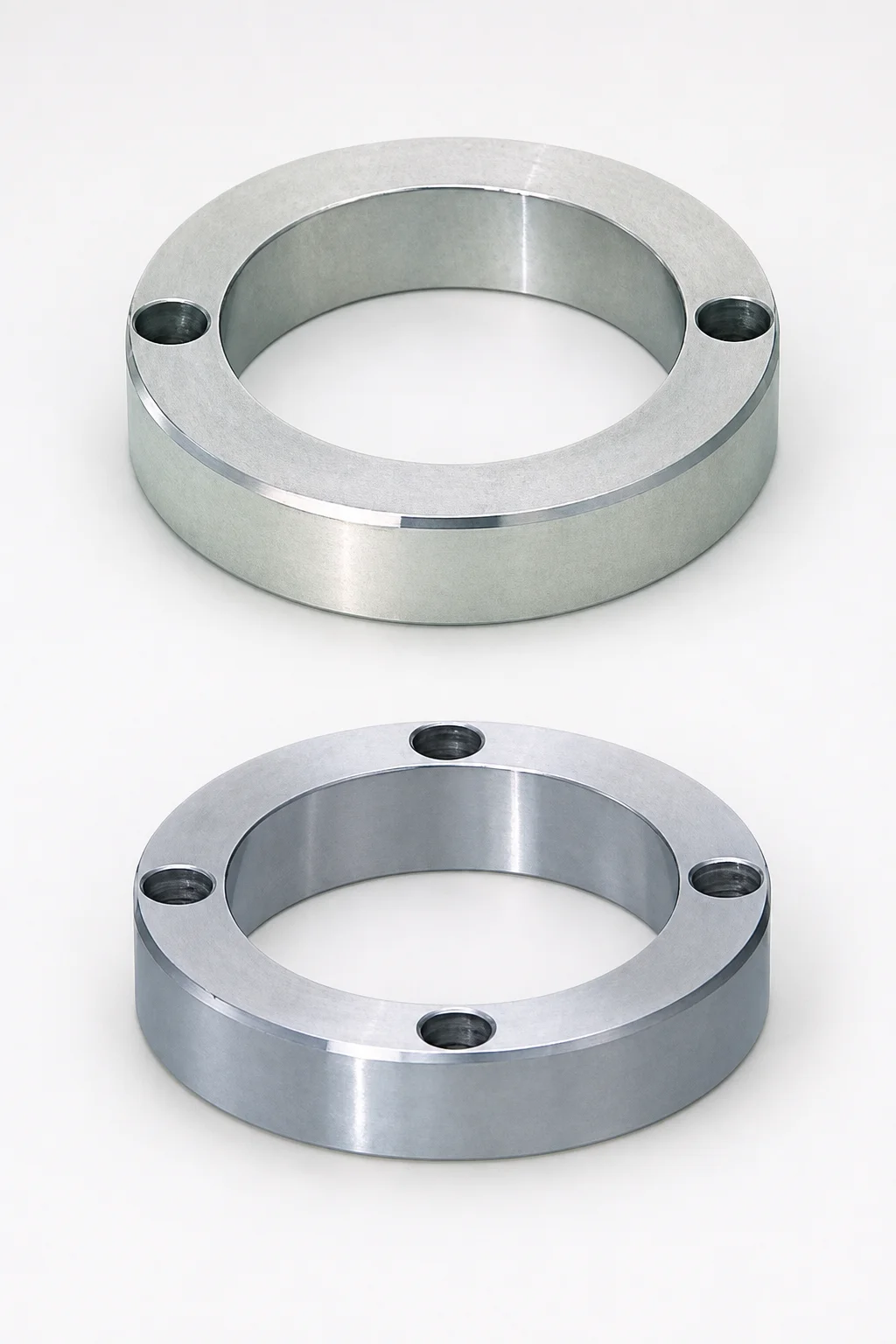
Locating Rings Through Hole Bolt Stopper
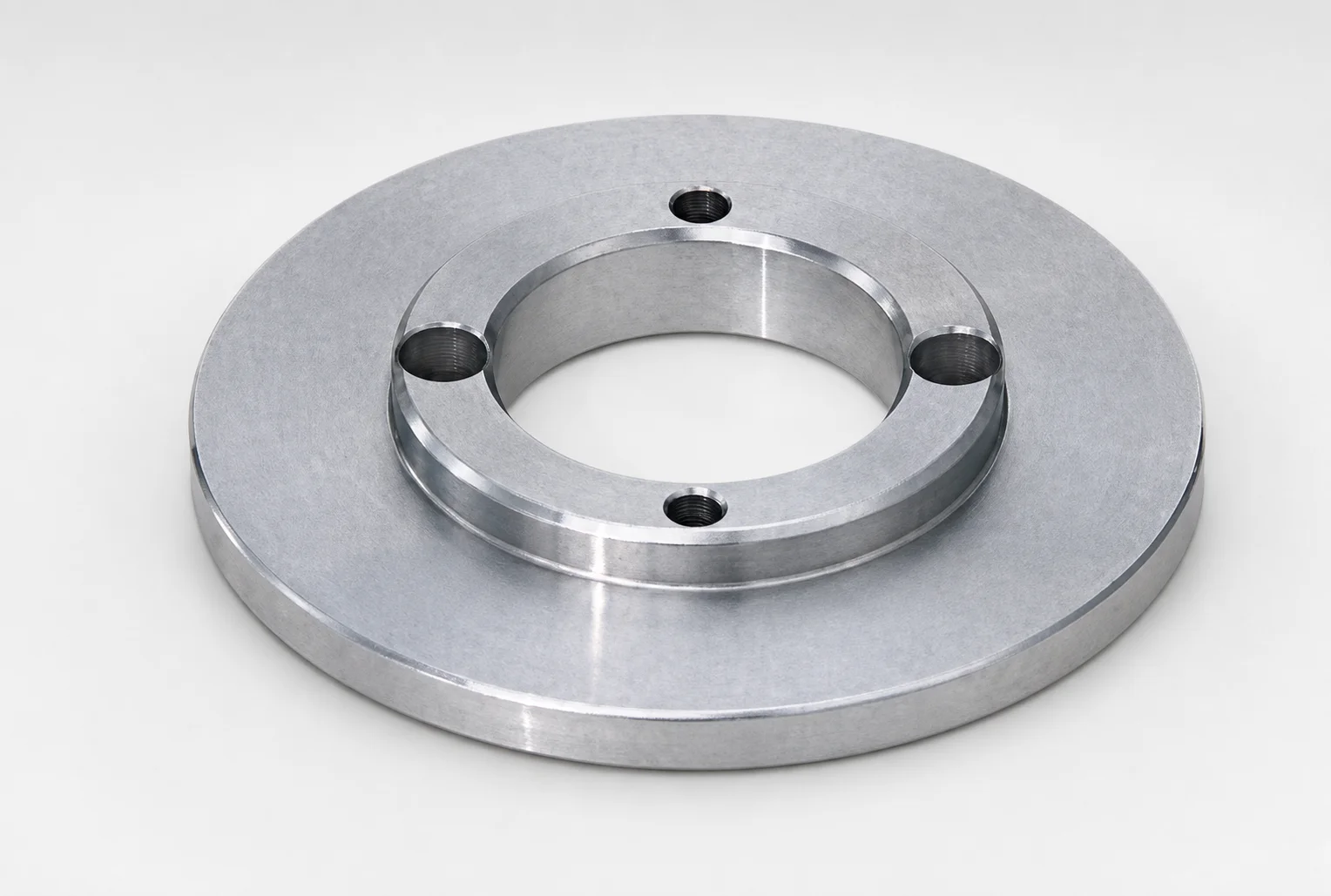
JIS Standard LRBW Reversible Locating Rings for 4-Bolt Holes
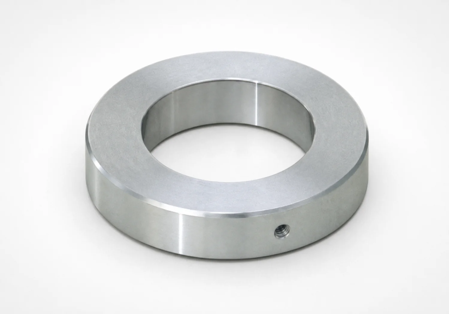
LAR Type Adapter Rings for Locating Rings
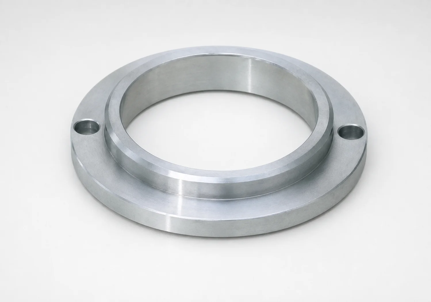
LRK Standard Locating Rings - Large Diameter Type, 2-Bolt Holes
Need Custom Specifications?
Our engineering team can help with custom configurations, material selection, and volume pricing.