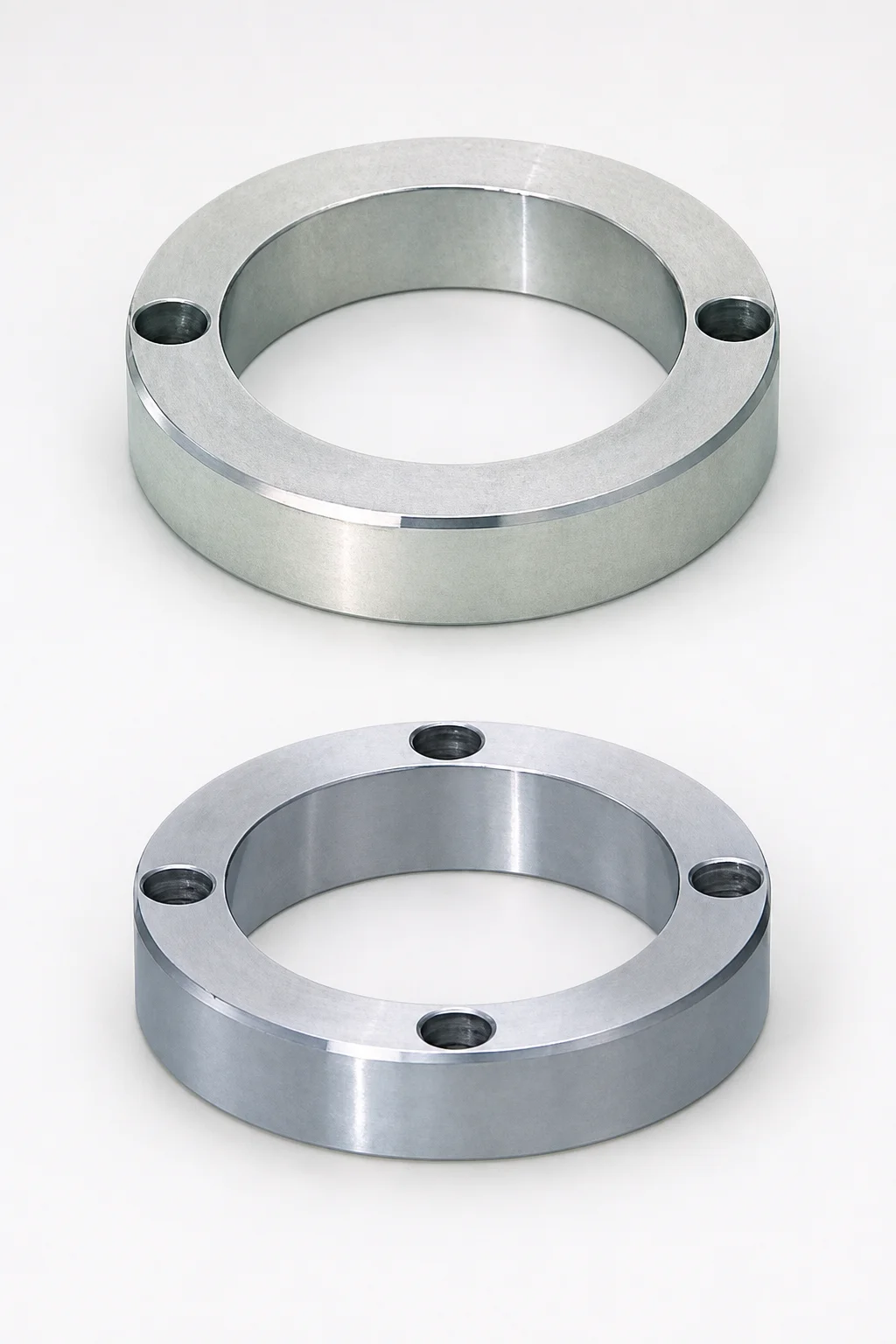
Locating Rings Through Hole Bolt Stopper
Locating Rings through hole bolt stopper provide stable mold alignment using a bolt stopper type interface and a standard type locating ring design. Built for repeatable setup in production die assemblies requiring through-hole fastening.
- Through-hole locating ring style supports consistent die alignment
- Bolt stopper type design improves positioning repeatability
- Standard locating ring construction suits common mold base interfaces
- Ideal for die sets using either 2-bolt or 4-bolt fastening layouts
Specifications
36 configurations available
| D (Locating Ring Outer Diameter) (mm) | Number of Bolts | T (Height) (mm) | type |
|---|---|---|---|
| 60 | 4 holes | 10 | - |
| 60 | 4 holes | 15 | - |
| 60 | 4 holes | 20 | - |
| 60 | 4 holes | 25 | - |
| 100 | 4 holes | 15 | - |
| 100 | 4 holes | 20 | - |
| 100 | 4 holes | 25 | - |
| 100 | 4 holes | 30 | - |
| 110 | 4 holes | 15 | - |
| 120 | 4 holes | 10 | - |
| 120 | 4 holes | 15 | - |
| 120 | 4 holes | 20 | - |
| 120 | 4 holes | 25 | - |
| 150 | 4 holes | 15 | - |
| 150 | 4 holes | 20 | - |
| 150 | 4 holes | 25 | - |
| 60 | 2 holes | 10 | - |
| 60 | 2 holes | 15 | - |
| 60 | 2 holes | 20 | - |
| 60 | 2 holes | 25 | - |
| 100 | 2 holes | 10 | - |
| 100 | 2 holes | 15 | - |
| 100 | 2 holes | 20 | - |
| 100 | 2 holes | 25 | - |
| 100 | 2 holes | 30 | - |
| 110 | 2 holes | 10 | - |
| 110 | 2 holes | 15 | - |
| 110 | 2 holes | 20 | - |
| 110 | 2 holes | 25 | - |
| 120 | 2 holes | 10 | - |
| 120 | 2 holes | 15 | - |
| 120 | 2 holes | 20 | - |
| 120 | 2 holes | 25 | - |
| 150 | 2 holes | 15 | - |
| 150 | 2 holes | 20 | - |
| 150 | 2 holes | 25 | - |
Product Guide
Application Scenarios+
This through-hole bolt stopper locating ring is used to lock die set position in injection mold tooling where repeatability of alignment is critical. It suits production die assemblies with standard locating ring interfaces and through-hole fastening so the upper and lower halves return to the same register after clamping.
- Automotive connector and housing molds: Use 4-bolt (four holes) mounting to maintain consistent cavity alignment under higher repeat cycle loads, especially when gate/runner components require tight register control.
- Appliance and electronics housings: The 2-bolt (two holes) configuration provides stable alignment while simplifying base layout, making it well matched to common die set footprints.
- Thin-wall consumer parts: The selected height options (T = 10–30 mm) help match die stack-up and stopper engagement depth, supporting repeatable setup during production maintenance.
With multiple outer diameters (D = 60–150 mm), this variant can be chosen to fit the locator requirements of your ring-style die base.
Material & Process Details+
The provided specifications for this locating ring define dimensional variants (D = 60, 100, 110, 120, 150 mm; T = 10–30 mm; 2-bolt or 4-bolt). No steel grade, hardness, or heat-treatment state is included in the input data, so material properties such as HRC, wear resistance, and toughness cannot be stated reliably.
In typical locating ring applications, engineers select a steel based on required wear resistance at the bolt-stopper interface and enough toughness to resist chipping during repeated clamping cycles. If you are using comparable locating-ring standards from your existing die base, match the locating ring material to the die set base material to reduce differential wear and ensure stable register.
- If an alternate steel option is offered in your procurement catalog, compare hardness (higher for wear resistance) versus toughness (better impact resistance).
- When heat treatment options (e.g., quench & temper, nitriding) exist, prioritize the state that best matches your expected contact pressure and maintenance interval.
Sizing & Selection Guide+
Correct selection is primarily driven by outer diameter (D), height (T), and whether your mold base uses 2-bolt or 4-bolt through-hole mounting.
- Outer diameter (D): Choose one of D = 60, 100, 110, 120, or 150 mm to match the locator bore/seat size in your die base design.
- Bolt pattern compatibility: Select the unit built for 2 holes or 4 holes to align with your through-hole fastening layout and ensure the stopper engages correctly during clamping.
- Height (T): Select T = 10, 15, 20, 25, or 30 mm based on required engagement depth within the die stack-up. This influences when the die halves reach the final register.
For fit and tolerance, base the clearance/interference on your existing locating-ring interface specifications. If your die design uses standard locating ring fits, keep the same tolerance class for D so the register is repeatable across production cycles.
Frequently Asked Questions
How do I choose between the 2-hole and 4-hole versions for a through-hole die set?+
Select based on your mold base fastening layout. This locating ring is offered for either 2 holes or 4 holes (bolt-stopper mounting). Matching the bolt count is essential so the ring seats and stopper engagement occur at the correct clamping position.
What outer diameter (D) options are available, and how should they match the die base locating seat?+
Available outer diameters are D = 60, 100, 110, 120, 150 mm. Choose the value that fits the corresponding locating seat/bore geometry in your die base. Using a different D than the seat design can prevent proper register and repeatable alignment.
How do I select the correct height (T) to match my die stack-up?+
Height options are T = 10, 15, 20, 25, 30 mm. Select T so the stopper engagement depth reaches the intended final die position under clamping. If the height is too short or too tall relative to your stack-up, you can get incomplete registration or excessive load on the interface.
Are there different steel grades or heat treatments for wear resistance, and what should I use for high-cycle molds?+
The provided input data lists dimensional variants only and does not specify a steel grade, hardness (HRC), or heat-treatment state. To determine wear resistance for high-cycle production, confirm the actual material/heat treatment from the supplier’s datasheet for this specific SKU. Then match the hardness/treatment to your expected contact pressure at the bolt-stopper interface.
Can this locating ring be used with standard ring-type locator designs in existing die assemblies?+
Yes—this variant is described as having a standard type locating ring design with a bolt stopper interface for repeatable alignment. It is intended for die sets using standard ring-type locator interfaces and through-hole fastening layouts (2-bolt or 4-bolt). This compatibility helps reduce rework when upgrading or replacing locator components.
Related Products
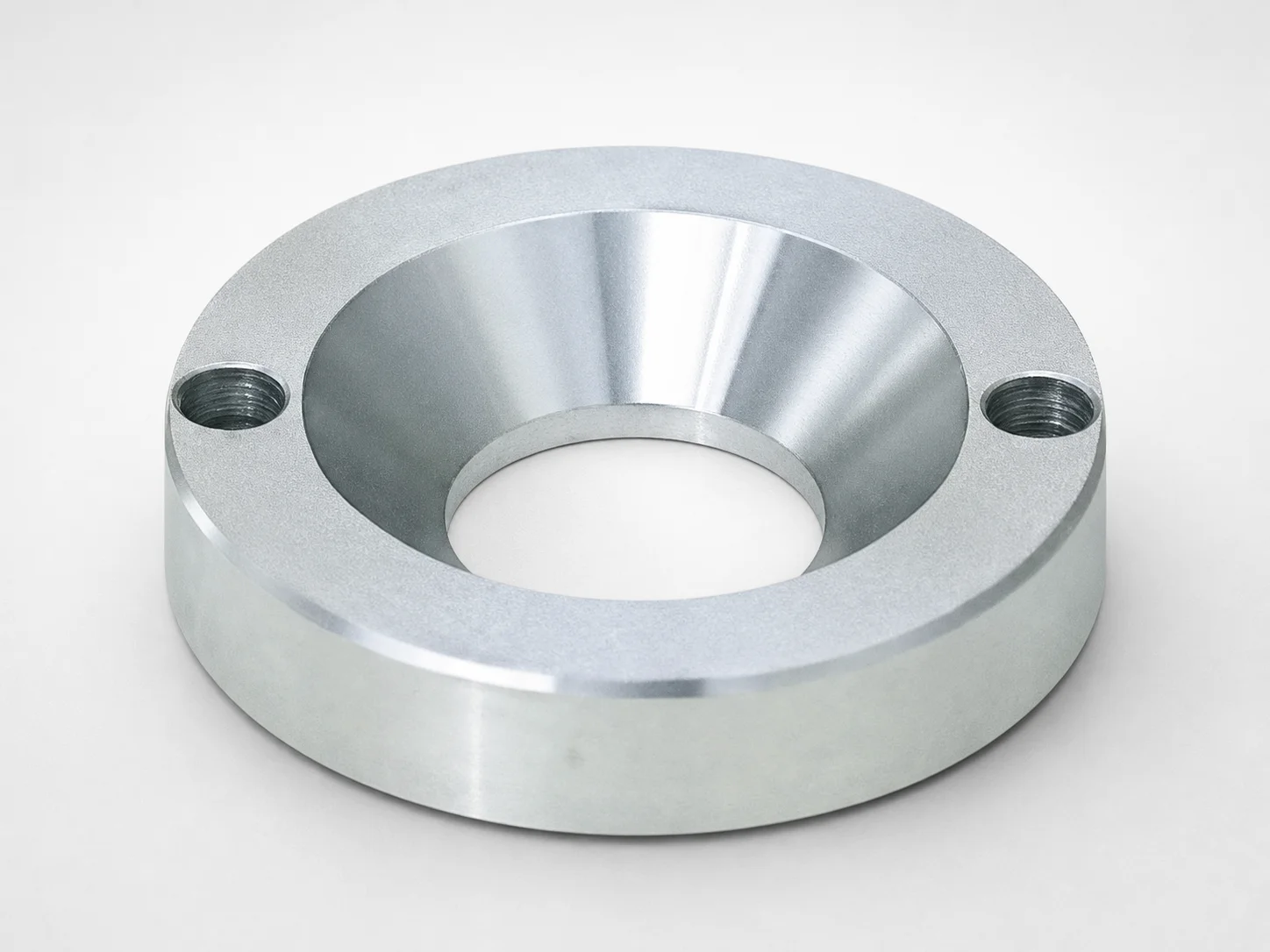
JIS Standard LRJS Locating Rings, Countersink, 2-Bolt Holes
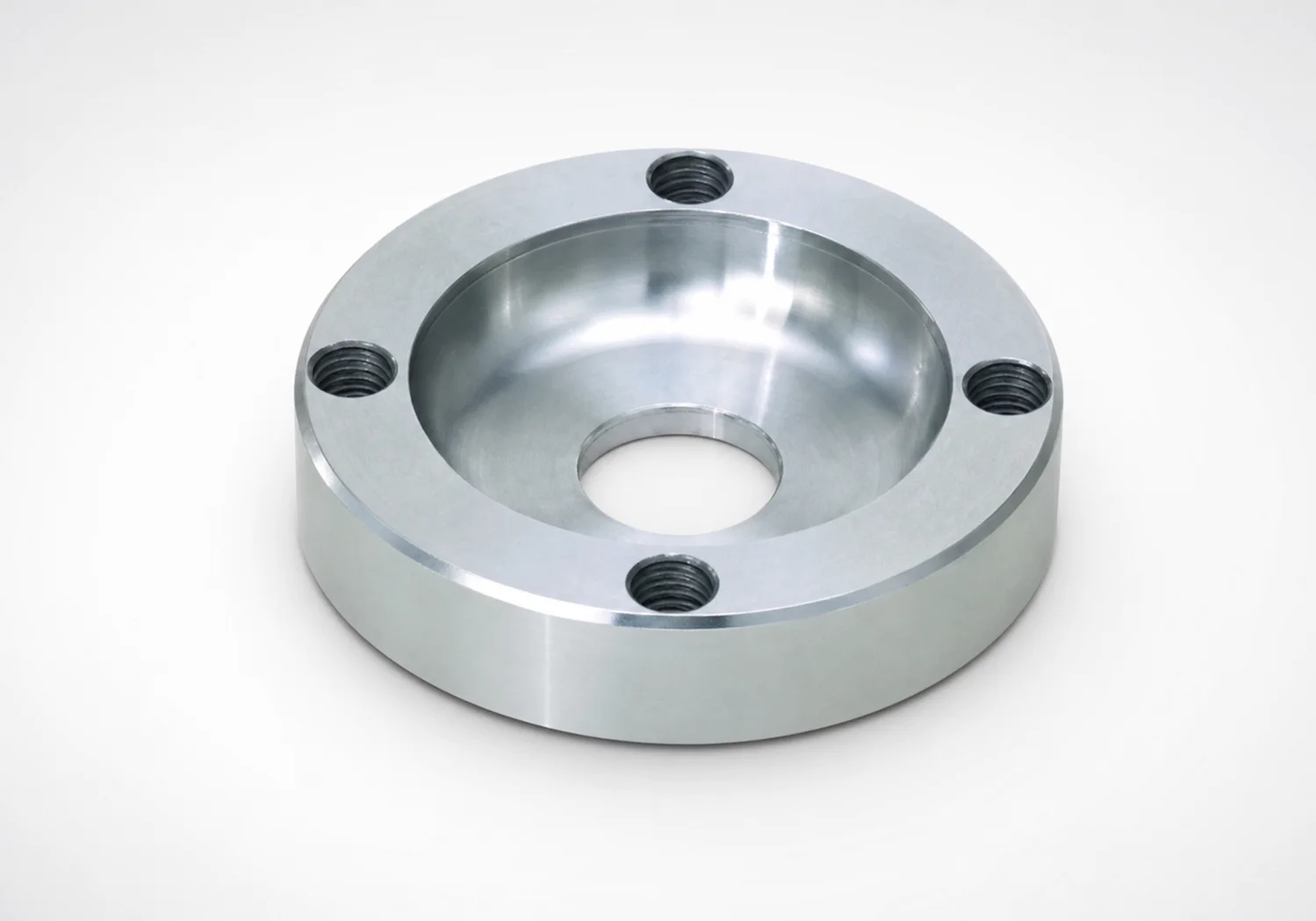
LRSS Locating Rings Counterbore 4-Bolt Holes
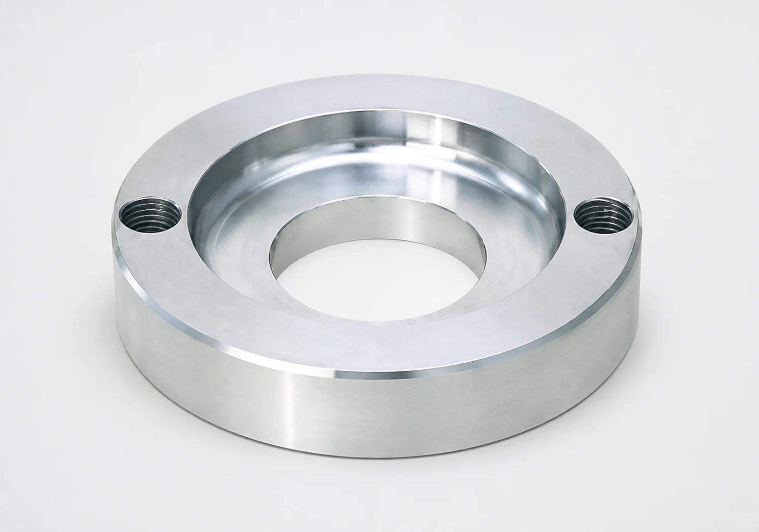
LRBD Locating Rings - Counterbore, 2-Bolt Holes
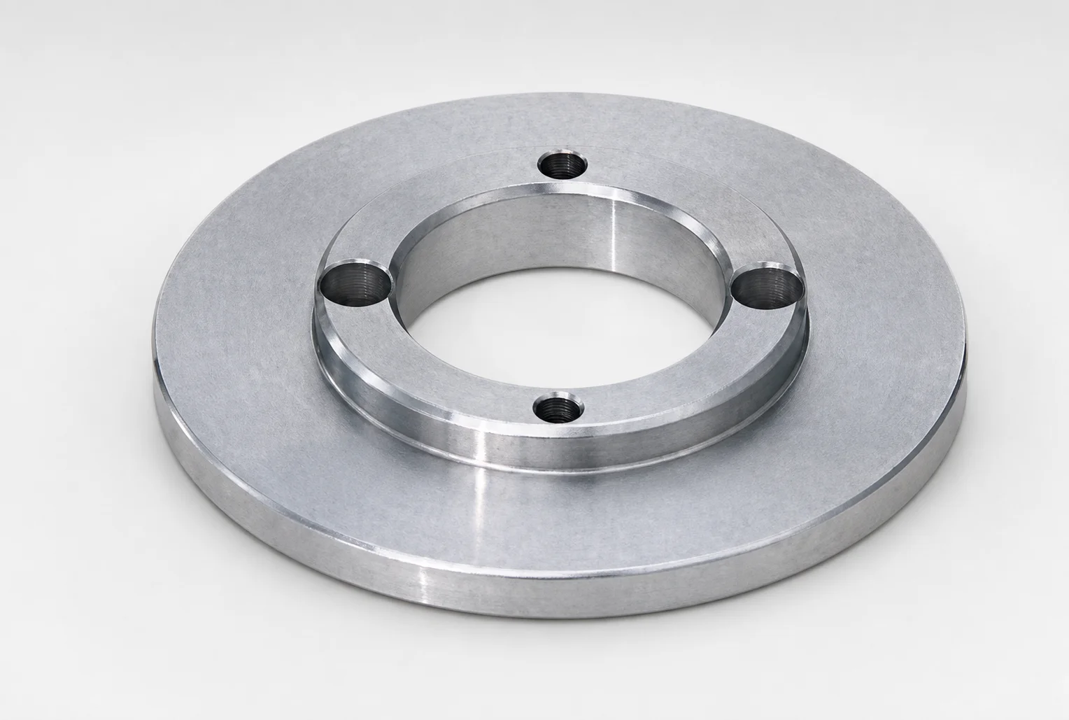
JIS Standard LRBW Reversible Locating Rings for 4-Bolt Holes
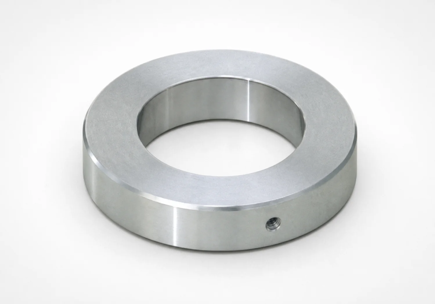
LAR Type Adapter Rings for Locating Rings
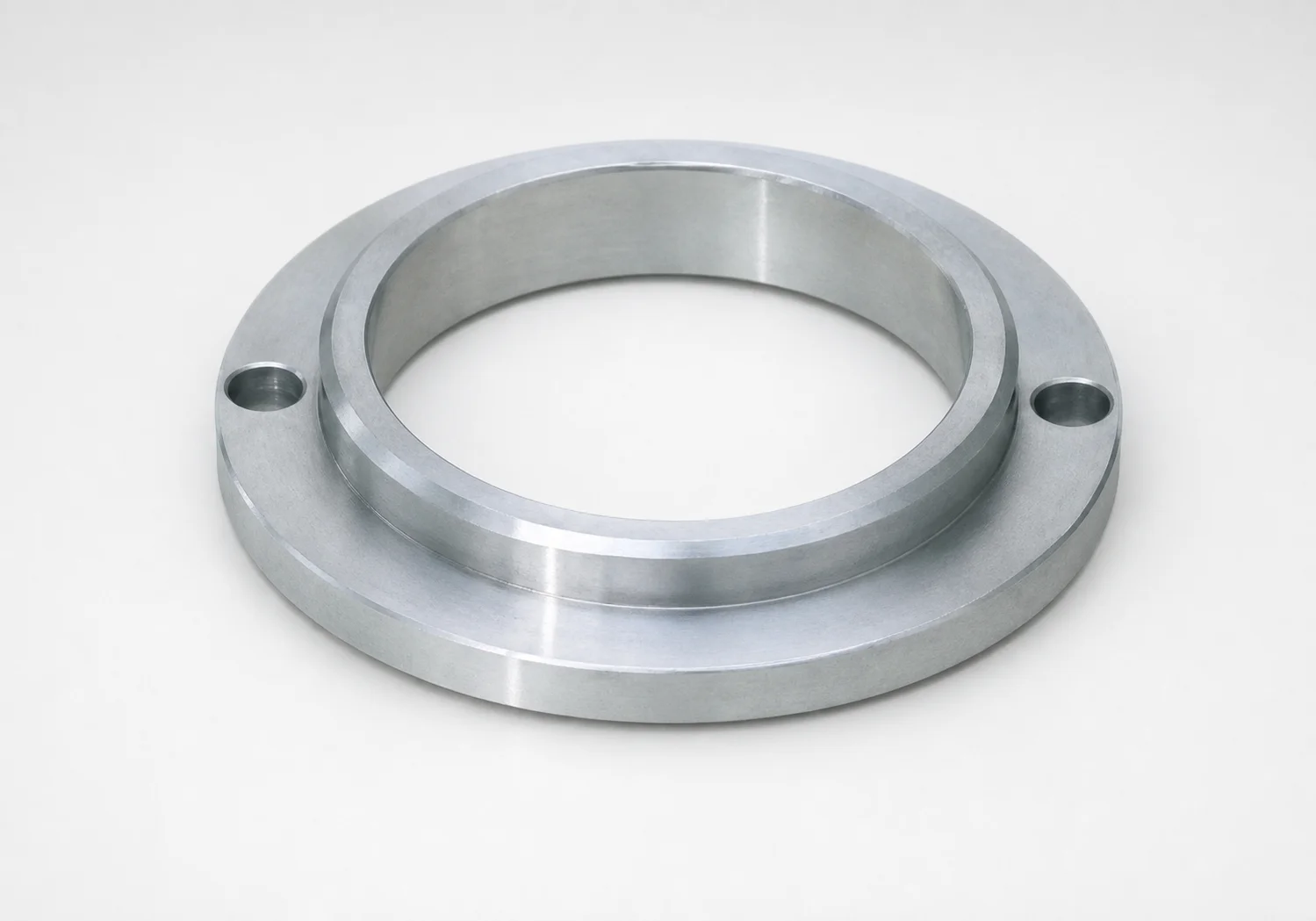
LRK Standard Locating Rings - Large Diameter Type, 2-Bolt Holes
Need Custom Specifications?
Our engineering team can help with custom configurations, material selection, and volume pricing.