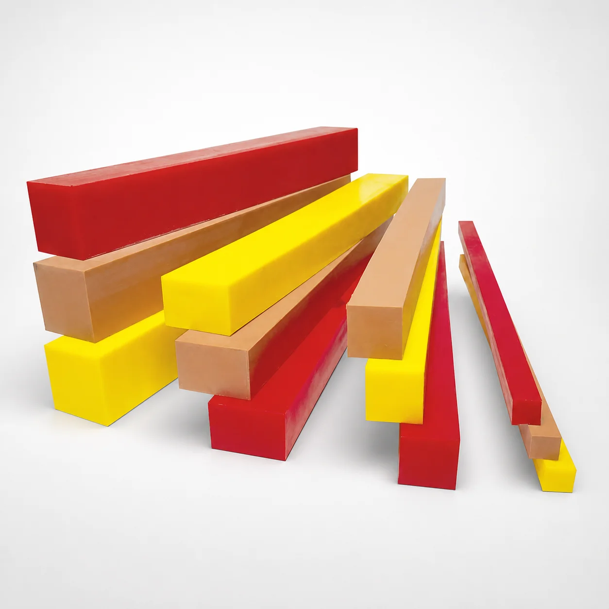
Pad Urethane Blocks with Hole
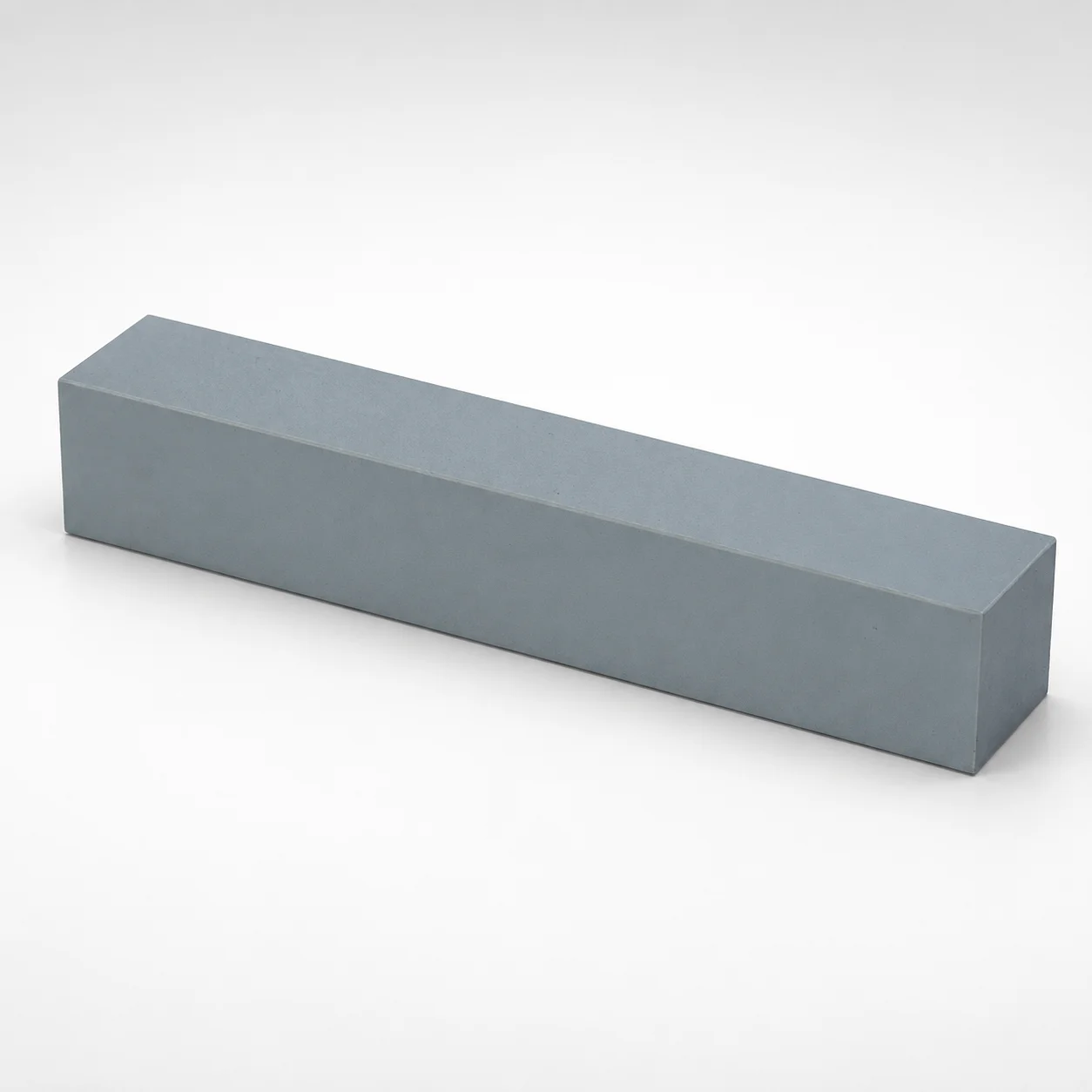
Pad urethane blocks with hole provide compact, stable bearing surfaces for precision tooling. Designed with a through hole to simplify location, fastenings, and repeatable setup in die and fixture applications.
- Pad shape for consistent contact and controlled load distribution
- Urethane construction tailored for tooling demands using selectable load-performance types
- Built for dimensional stability to support repeatable assembly and alignment
- Commonly used as urethane die components, stops, and locator blocks in forming work
Specifications
120 configurations available
| Urethane Type | Length (L) (mm) | T (Height) (mm) | A (Width) (mm) | B (Width) (mm) |
|---|---|---|---|---|
| PO-652 Tan (Very high load) | 100 | 45 | 110 | 45 |
| PO-652 Tan (Very high load) | 1000 | 45 | 110 | 45 |
| PO-670 Black (Very low load) | 100 | 45 | 110 | 45 |
| PO-670 Black (Very low load) | 1000 | 45 | 110 | 45 |
| PO-650 Red (Medium load) | 100 | 45 | 110 | 45 |
| PO-650 Red (Medium load) | 1000 | 45 | 110 | 45 |
| CU-290 Yellow (High load) | 100 | 45 | 110 | 45 |
| CU-290 Yellow (High load) | 1000 | 45 | 110 | 45 |
| PO-652 Tan (Very high load) | 415 | 45 | 110 | 45 |
| PO-670 Black (Very low load) | 415 | 45 | 110 | 45 |
| PO-650 Red (Medium load) | 415 | 45 | 110 | 45 |
| CU-290 Yellow (High load) | 415 | 45 | 110 | 45 |
| PO-652 Tan (Very high load) | 500 | 45 | 110 | 45 |
| PO-670 Black (Very low load) | 500 | 45 | 110 | 45 |
| PO-650 Red (Medium load) | 500 | 45 | 110 | 45 |
| CU-290 Yellow (High load) | 500 | 45 | 110 | 45 |
| PO-652 Tan (Very high load) | 835 | 45 | 110 | 45 |
| PO-670 Black (Very low load) | 835 | 45 | 110 | 45 |
| PO-650 Red (Medium load) | 835 | 45 | 110 | 45 |
| CU-290 Yellow (High load) | 835 | 45 | 110 | 45 |
| PO-652 Tan (Very high load) | 100 | 25 | 25 | 25 |
| PO-652 Tan (Very high load) | 1000 | 25 | 25 | 25 |
| PO-670 Black (Very low load) | 100 | 25 | 25 | 25 |
| PO-670 Black (Very low load) | 1000 | 25 | 25 | 25 |
| PO-650 Red (Medium load) | 100 | 25 | 25 | 25 |
| PO-650 Red (Medium load) | 1000 | 25 | 25 | 25 |
| CU-290 Yellow (High load) | 100 | 25 | 25 | 25 |
| CU-290 Yellow (High load) | 1000 | 25 | 25 | 25 |
| PO-652 Tan (Very high load) | 415 | 25 | 25 | 25 |
| PO-670 Black (Very low load) | 415 | 25 | 25 | 25 |
| PO-650 Red (Medium load) | 415 | 25 | 25 | 25 |
| CU-290 Yellow (High load) | 415 | 25 | 25 | 25 |
| PO-652 Tan (Very high load) | 500 | 25 | 25 | 25 |
| PO-670 Black (Very low load) | 500 | 25 | 25 | 25 |
| PO-650 Red (Medium load) | 500 | 25 | 25 | 25 |
| CU-290 Yellow (High load) | 500 | 25 | 25 | 25 |
| PO-652 Tan (Very high load) | 835 | 25 | 25 | 25 |
| PO-670 Black (Very low load) | 835 | 25 | 25 | 25 |
| PO-650 Red (Medium load) | 835 | 25 | 25 | 25 |
| CU-290 Yellow (High load) | 835 | 25 | 25 | 25 |
| PO-652 Tan (Very high load) | 100 | 25 | 30 | 25 |
| PO-652 Tan (Very high load) | 1000 | 25 | 30 | 25 |
| PO-670 Black (Very low load) | 100 | 25 | 30 | 25 |
| PO-670 Black (Very low load) | 1000 | 25 | 30 | 25 |
| PO-650 Red (Medium load) | 100 | 25 | 30 | 25 |
| PO-650 Red (Medium load) | 1000 | 25 | 30 | 25 |
| CU-290 Yellow (High load) | 100 | 25 | 30 | 25 |
| CU-290 Yellow (High load) | 1000 | 25 | 30 | 25 |
| PO-652 Tan (Very high load) | 415 | 25 | 30 | 25 |
| PO-670 Black (Very low load) | 415 | 25 | 30 | 25 |
Product Guide
Application Scenarios+
Pad urethane blocks with a through hole are used in injection mold tooling wherever a compact, repeatable bearing or locating surface is needed. The through hole simplifies fastener-based positioning and supports repeatable setup when dies, carriers, or fixture elements are removed and reinstalled.
- Automotive and electronics connector molding setups: Use the urethane pad as a die or slide bearing and as a locator/stop to stabilize contact and control load transfer during frequent press cycles.
- Die attach and alignment fixtures: The hole enables pin or bolt alignment for consistent clamping locations, helping maintain fixture geometry during maintenance intervals.
- Forming and tooling work supports: Select the appropriate load-performance urethane type to tune compliance—lower load variants reduce deflection, while higher load variants improve support under heavier stamping/forming loads.
This variant’s through-hole layout and urethane pad shape make it well suited for stable positioning and controlled load distribution.
Material & Process Details+
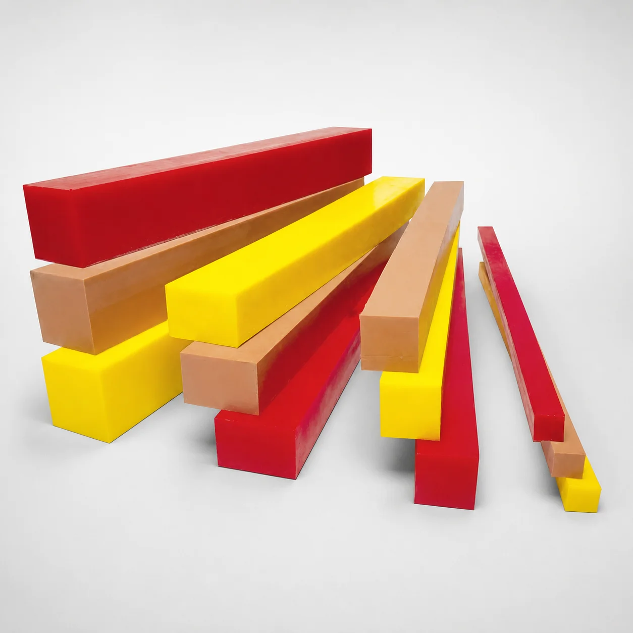
This component uses a selectable urethane load-performance type, allowing engineers to tune stiffness and damping without changing the tooling interface geometry. Available types include PO-652 Tan (Very high load), PO-670 Black (Very low load), PO-650 Red (Medium load), and CU-290 Yellow (High load).
- Wear/deflection trade-off: Higher-load urethane types are intended to provide stronger support with reduced sag under sustained contact, while very-low-load types provide greater compliance for fine positioning or shock absorption.
- Heat treatment and manufacturing: As a urethane pad system, performance relies on the molded/formed polyurethane chemistry and curing rather than steel heat treatment cycles. Final properties are established through the manufacturer’s polyurethane production and curing process.
- Material comparison: If your process is sensitive to pad compression, choose PO-670 Black; for heavier contact loads and higher rigidity, choose PO-652 Tan or CU-290 Yellow.
Sizing & Selection Guide+
Select the block dimensions by matching the contact footprint and mounting hole location to the mold cavity/core or fixture interface. Confirm that the pad’s width parameters (A and B) fit within the available tooling envelope without interfering with adjacent tie-bar, ejector, or gate components.
- Length (L): Choose from 100, 415, 500, 835, or 1000 mm to match the required bearing/stop span along the die or fixture surface.
- Height (T): Available values are 25, 30, 45, or 50 mm; select based on allowable stack-up and deflection requirements.
- Planform widths: Use A options 110, 80, 75, 50, 30, or 25 mm and B options 45, 50, 30, or 25 mm to achieve the target contact area.
Because the hole enables repeatable mounting, ensure the mounting interface (bolt/pin clearances) is compatible with your fastener diameter and that the pad is constrained to prevent shear movement under cyclic loading. Dimensions are available as fixed catalog sizes rather than continuously configurable values.
Frequently Asked Questions
Which urethane type should I choose for high-load stop or bearing use in mold fixtures?+
For high contact support with reduced compression under load, select PO-652 Tan (Very high load) or CU-290 Yellow (High load). If you need a mid-level stiffness/deflection balance, use PO-650 Red (Medium load). For applications where compliance is beneficial and deflection should be higher, choose PO-670 Black (Very low load).
How do I select the pad dimensions (L, T, A, B) so it fits my mold cavity/core tooling envelope?+
Use L to cover the required bearing/stop span and choose from 100, 415, 500, 835, or 1000 mm. Match T (available 25, 30, 45, 50 mm) to your allowable stack height and compression budget. Set A from 110, 80, 75, 50, 30, 25 mm and B from 45, 50, 30, 25 mm to ensure the footprint clears adjacent tooling features.
What advantages does the through hole provide for repeatable die and fixture alignment?+
The pad includes a through hole intended to simplify location using a fastener or alignment pin. In die maintenance scenarios, the hole-based mounting helps repeat the same position after reinstallation, improving setup consistency. Ensure your mounting hardware and clearances are compatible with the hole geometry and that the pad is constrained against lateral slip.
Are these urethane pad blocks heat treated like steel mold components?+
No—urethane pad performance is established through polyurethane molding/curing rather than steel heat treatment cycles. The key selectable “material state” is the urethane type (e.g., PO-652, PO-670, PO-650, CU-290), which determines load-performance characteristics. For steel wear surfaces, you may still pair the pad with hardened guiding components as needed.
Can I specify multiple sizes for a tooling train without changing the mounting concept?+
Yes. The design concept remains compatible because each variant includes the through hole, but you can select different fixed sizes for L (100–1000 mm) and T (25–50 mm) to match different mounting locations. Choose A and B from the provided catalog ranges to tailor the contact area while keeping the same fastening approach.
Related Products
Need Custom Specifications?
Our engineering team can help with custom configurations, material selection, and volume pricing.