Blanking Punches
Specialized Cutoff & Separation Geometry. Browse 2 products from MISUMI and DAYTON with configurable dimensions and same-day shipping on standard catalog items.
Blanking Punches (2 Products)
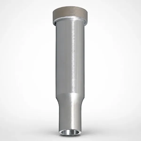
SPCPD Single-Stepped Blanking Punches
SPCPD single-stepped blaking punches (SKD11 equivalent steel) for precision blanking and punching. Built for consistent fit, tool life, and stable production.
View Details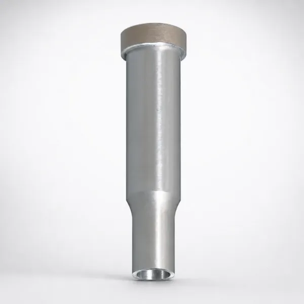
Alpha Treatment Blanking Punches (P-SPCPD)
Alpha Treatment Blanking Punches (P-SPCPD) with nano-crystallized surface hardness improvement, reduced friction microtexture, and stable dimensions for smoo...
View DetailsBlanking Mechanics: Shear Force & Clearance
Blanking punches are designed specifically for separation (cutoff) operations where the blank is the desired part. The geometry differs from piercing punches in clearance ratios, edge preparation, and force distribution.
Shear Force Calculation
Blanking force: F = L x t x tau, where L = perimeter of blank (mm), t = material thickness (mm), tau = material shear strength (MPa). For mild steel (SPCC): tau = 250-320 MPa. For stainless steel (SUS304): tau = 450-550 MPa. For AHSS (DP590): tau = 350-450 MPa. Example: blanking a 50mm diameter circle from 1.5mm SPCC requires F = (pi x 50) x 1.5 x 300 = 70.7 kN.
Die Clearance for Blanking
Optimal blanking clearance: 5-8% of material thickness per side for mild steel, 7-10% for stainless steel, 8-12% for AHSS. Under-clearance causes: excessive punch force, rapid edge wear, secondary shear (double breakage lines on blank edge). Over-clearance causes: excessive burr height, poor edge quality, material rollover.
Edge Preparation
Blanking punch edges are typically ground to a 0.01-0.03mm radius (not a sharp knife edge). This micro-radius extends edge life by 3-5x by distributing the initial impact stress. Sharp edges chip within the first 1,000-5,000 hits on hardened materials.
About Blanking Punches
Blanking punches are engineered specifically for material separation operations where the punched-out piece (blank) is the finished part. Their geometry is optimized for clean edge quality, consistent blank dimensions, and extended tool life in continuous blanking operations. Available in SKD11 (general purpose) and SKH51 (high-speed/abrasive materials) with micro-radius edge preparation for impact resistance.
Application Scenarios
Motor Lamination Blanking
Electric motor stator and rotor laminations require blanking of complex shapes from silicon steel with tight dimensional tolerances and minimal burr.
Why blanking punches fit: Specialized edge preparation and clearance optimization for silicon steel (high silicon content increases abrasiveness). SKH51 or SKH40 grades resist the accelerated wear from silicon steel stamping.
Washer & Gasket Production
High-volume circular blank production for washers, gaskets, and shim plates requires consistent blank diameter and edge quality across millions of parts.
Why blanking punches fit: Circular blanking geometry with precision-ground OD maintains blank diameter consistency within +/-0.02mm across the punch life cycle between regrinds.
Frequently Asked Questions
How does blanking punch geometry differ from standard piercing punches?+
What clearance is recommended between blanking punches and die buttons?+
Can blanking punches handle abrasive materials like spring steel?+
What custom surface treatments are available to extend blanking tool life?+
Engineering Resources
Need a Custom Quote?
Send your specifications and receive a quote. MOQ: 1 piece. Custom dimensions available.