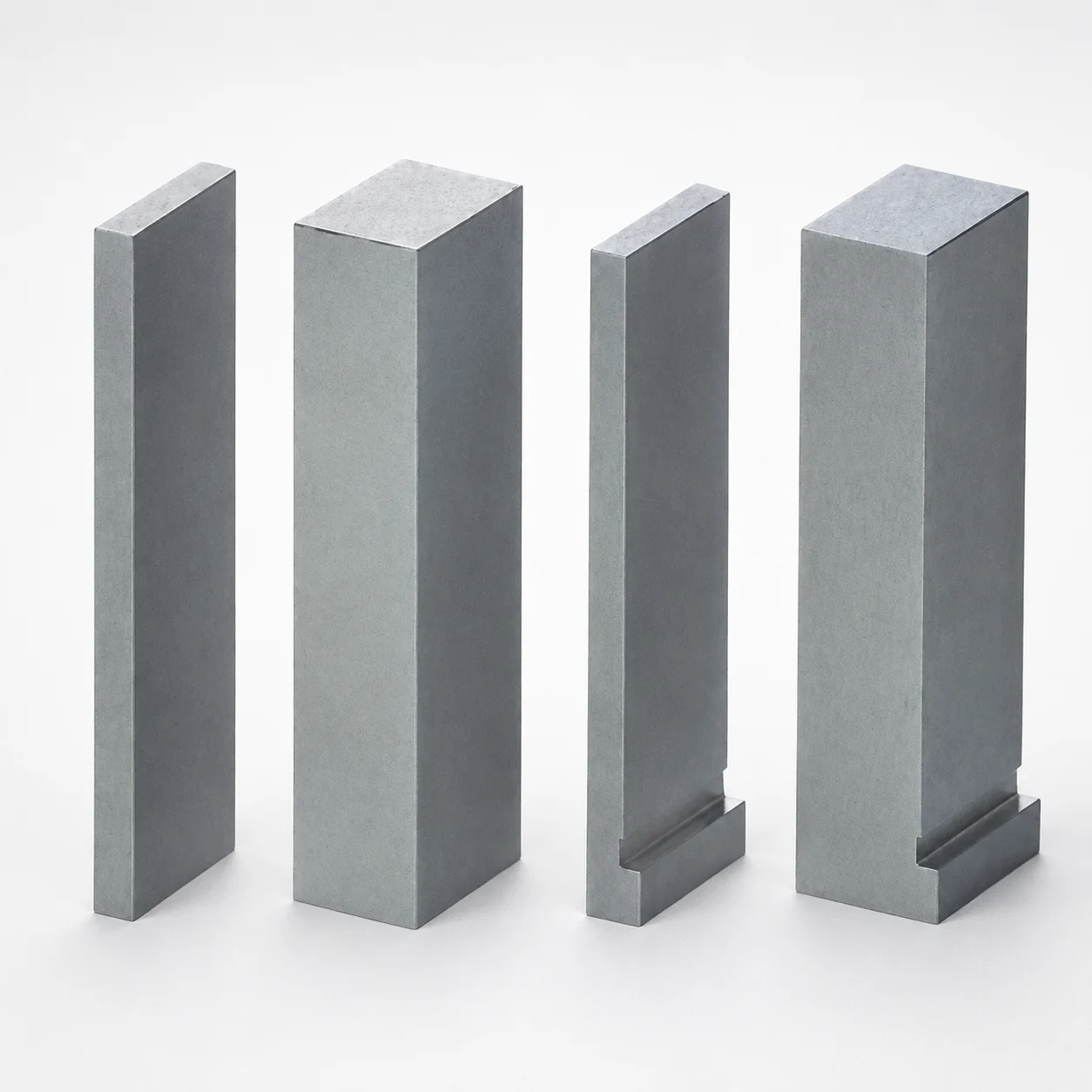
Various Steel Block Core Pins No Tip Straight Flange
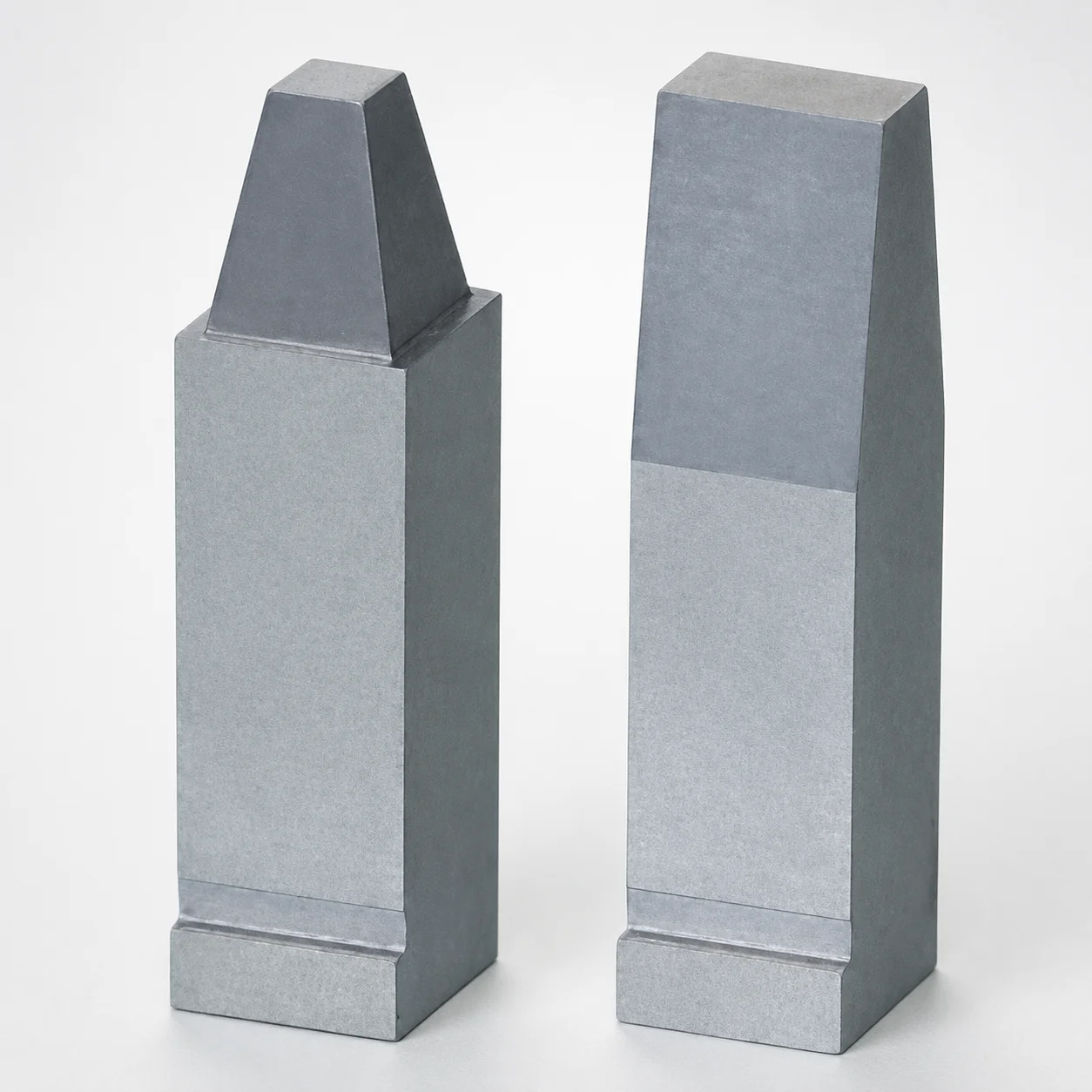
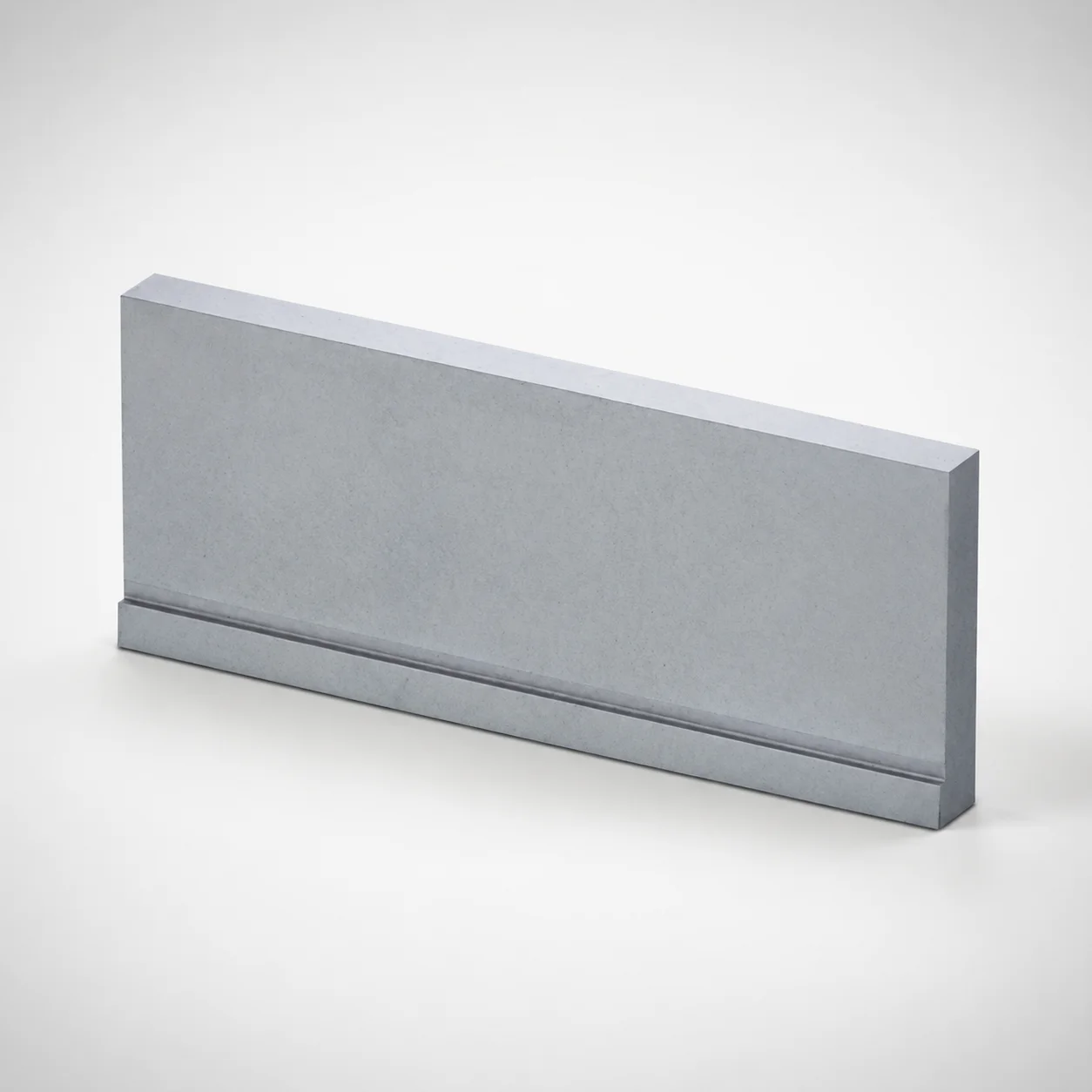
Block Core Pins no tip straight flange support stable block core positioning with a straight profile and optional flange. This no-tip design helps maintain consistent seating during mold assembly and core installation.
- Straight block core pin body without tip processing for dependable alignment
- Made from various mold steels to match different wear and corrosion requirements
- Flange position set at F = 0° for repeatable assembly geometry
- Works with precision mold blocks where flange-based positioning is required
Specifications
21 configurations available
| Material | Includes Flange | F (Flange Position) (°) | Hardness | W (External shape) (mm) | H (Flange thickness) (mm) | HC (Changes the flange thickness) (mm) | L (L dimension) (mm) | P (Outer diameter) (mm) | type |
|---|---|---|---|---|---|---|---|---|---|
| ORVAR SUPREME | Yes | 0 | 51~53HRC | 1 ~ 20 | 4 ~ 6 | - | 10 ~ 70 | 1 ~ 20 | - |
| ORVAR SUPREME | Yes | 0 | 51~53HRC | 1 ~ 20 | - | 2 ~ 6 | 10 ~ 70 | 1 ~ 20 | - |
| DH2F | Yes | 0 | - | 2 ~ 20 | 4 ~ 6 | - | 10 ~ 70 | 2 ~ 20 | - |
| DH2F | Yes | 0 | - | 2 ~ 20 | - | 2 ~ 6 | 10 ~ 70 | 2 ~ 20 | - |
| SKH51 | Yes | 0 | 61~64HRC | 1 ~ 20 | 4 ~ 6 | - | 10 ~ 100 | 1 ~ 20 | - |
| SKH51 | Yes | 0 | 61~64HRC | 1 ~ 20 | - | 2 ~ 6 | 10 ~ 100 | 1 ~ 20 | - |
| NAK80 | Yes | 0 | 37~43HRC | 1 ~ 20 | 4 ~ 6 | - | 10 ~ 100 | 1 ~ 20 | - |
| NAK80 | Yes | 0 | 37~43HRC | 1 ~ 20 | - | 2 ~ 6 | 10 ~ 100 | 1 ~ 20 | - |
| RIGOR | Yes | 0 | 53~55HRC | 1 ~ 20 | 4 ~ 6 | - | 10 ~ 70 | 1 ~ 20 | - |
| RIGOR | Yes | 0 | 53~55HRC | 1 ~ 20 | - | 2 ~ 6 | 10 ~ 70 | 1 ~ 20 | - |
| ORVAR SUPREME | No | - | 51~53HRC | 1 ~ 20 | - | - | 10 ~ 70 | 1 ~ 20 | - |
| DH2F | No | - | - | 2 ~ 20 | - | - | 10 ~ 70 | 2 ~ 20 | - |
| NAK80 | No | - | 37~43HRC | 1 ~ 20 | - | - | 10 ~ 100 | 1 ~ 20 | - |
| RIGOR | No | - | 53~55HRC | 1 ~ 20 | - | - | 10 ~ 70 | 1 ~ 20 | - |
| ORVAR SUPREME | No | - | 47~49HRC | 1 ~ 20 | - | - | 10 ~ 70 | 1 ~ 20 | - |
| STAVAX ESR | No | - | 27~35HRC | 5.01 ~ 20 | - | - | 10 ~ 100 | 5.01 ~ 20 | - |
| ORVAR SUPREME | Yes | 0 | 47~49HRC | 1 ~ 20 | 4 ~ 6 | - | 10 ~ 70 | 1 ~ 20 | - |
| ORVAR SUPREME | Yes | 0 | 47~49HRC | 1 ~ 20 | - | 2 ~ 6 | 10 ~ 70 | 1 ~ 20 | - |
| STAVAX ESR | Yes | 0 | 27~35HRC | 5.01 ~ 20 | 4 ~ 6 | - | 10 ~ 100 | 5.01 ~ 20 | - |
| STAVAX ESR | Yes | 0 | 27~35HRC | 5.01 ~ 20 | - | 2 ~ 6 | 10 ~ 100 | 5.01 ~ 20 | - |
| SKH51 | No | - | 61~64HRC | 1 ~ 20 | - | - | 10 ~ 100 | 1 ~ 20 | - |
Product Guide
Application Scenarios+
These straight, no-tip block core pins with an F = 0° straight flange position are used in precision die-casting and large mold tool assemblies where consistent core seating is critical. In automotive connector and sensor housing molds, the pin’s straight profile and flange geometry help maintain repeatable alignment during block core installation, supporting stable parting and reducing mis-seating over repeated cycles.
- Automotive die-casting housings: Straight no-tip seating supports reliable core positioning in high-cycle, tight-fit block systems.
- Medical device housing inserts: Flange-based locating geometry supports accurate assembly repeatability for fine-tolerance cavities.
- Industrial connector housings: Multiple available steels allow matching wear/corrosion needs to aluminum/zinc environments.
Because the product variant offers optional flange configuration and multiple steel options, it can be specified to the required wear resistance and corrosion resistance without changing the core alignment interface.
Material & Process Details+
Block core pins are available in several mold steels: ORVAR SUPREME, DH2F, SKH51, NAK80, RIGOR, and STAVAX ESR. Hardness is offered across multiple grades, with listed ranges of 51–53 HRC, 61–64 HRC, 37–43 HRC, 53–55 HRC, 47–49 HRC, and 27–35 HRC, enabling trade-offs between wear resistance and toughness.
- High-hardness options (e.g., 61–64 HRC) favor abrasion/long-run dimensional stability.
- Mid to lower hardness options (e.g., 27–35 HRC, 37–43 HRC) can improve toughness and reduce risk of chipping under assembly loads.
Heat treatment state is not explicitly provided in the input data, so selection should be aligned with the chosen steel’s standard mold heat-treatment route (e.g., hardened and tempered for wear grades) and the required hardness window.
Sizing & Selection Guide+
To select the correct block core pin, match the pin’s diameter and length to the mold’s locating interface and the core/block seating depth. The product provides variable ranges for P (outer diameter) of 1–20 mm (with options such as 2–20 mm and 5.01–20 mm) and L of 10–70 mm or 10–100 mm depending on the configuration.
- Choose P to fit the mating core pin bore or alignment hole in your mold block, considering clearance for assembly and thermal expansion.
- Choose L to reach the required seating depth without bottoming out on block features.
- Flange constraints: flange thickness H = 4–6 mm and flange thickness change HC = 2–6 mm are fixed ranges when flange is included; flange position is fixed at F = 0°.
Because tolerance values are not provided, engineers should verify target fit (clearance/interference) using the mating bore specification in the mold design and the selected steel’s expected thermal growth.
Frequently Asked Questions
Which hardness range should be selected for block core pins when targeting long-run wear in die-casting tools?+
How does the no-tip straight flange design affect alignment during block core installation?+
What flange dimensions are fixed, and what should be checked in the mold design when flange is included?+
How should I select P (outer diameter) and L (length) for the correct fit in core alignment bores?+
Can different steel grades be used to match wear and corrosion requirements in die-casting components?+
Related Products
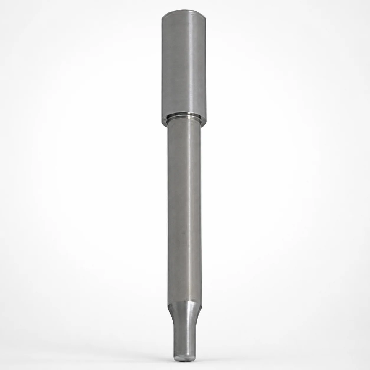
TiCN Option Powder High Speed Steel Round Stopper Punches Single-Stepped
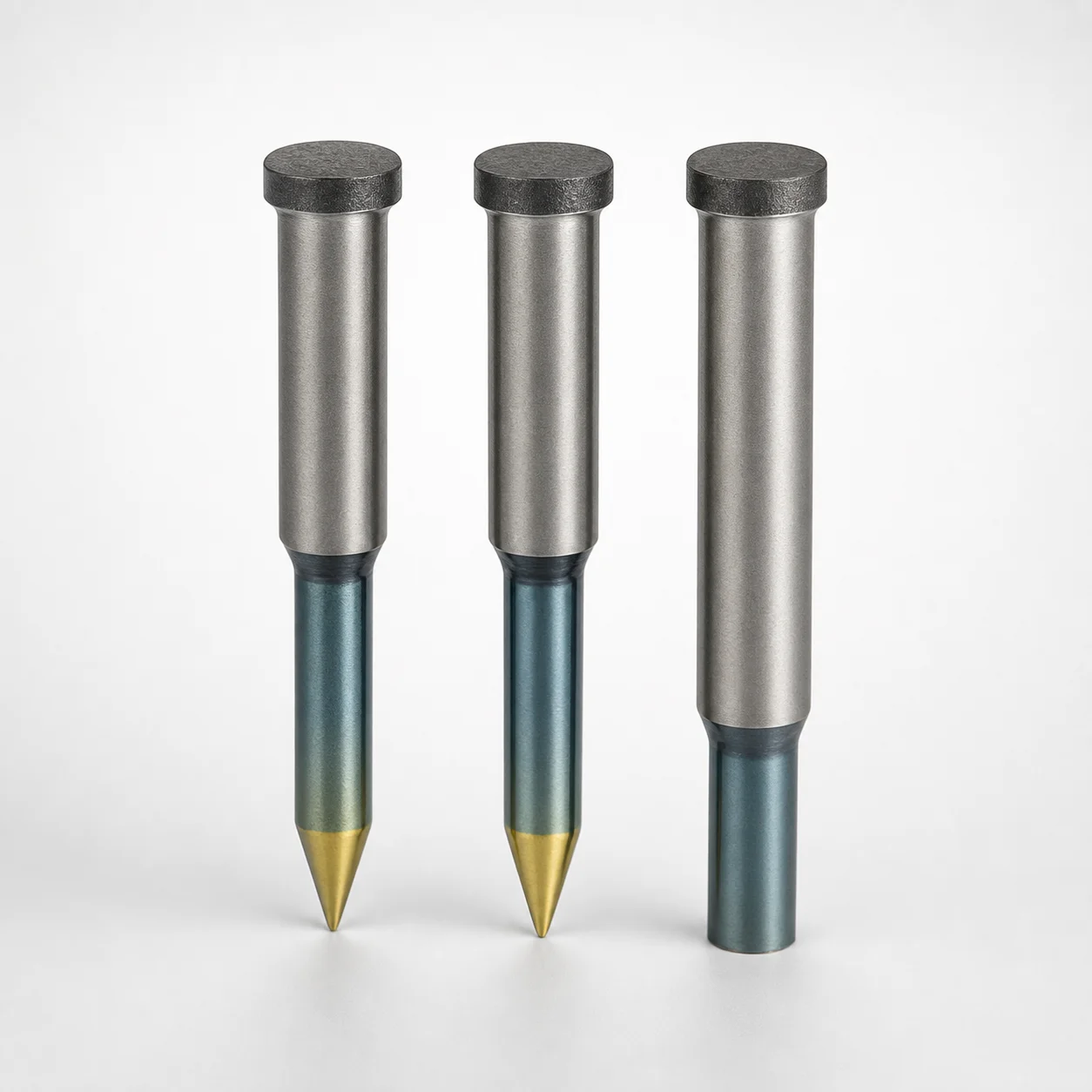
Powdered High-Speed Steel Round Stopper Punches Single-Stepped
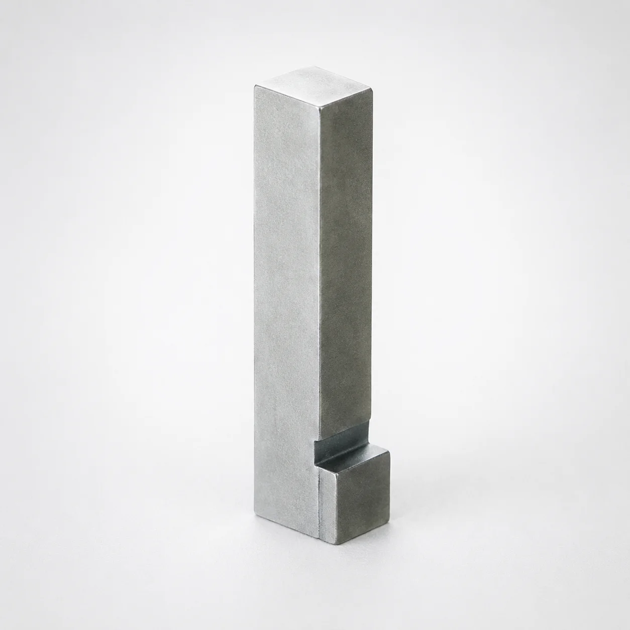
JIS Standard Steel Block Core Pins No Tip No Engraving
Steel Block Core Pins No-Tip with Flange
Block Core Pins No Tip Processing With Flange
JST PTFE Pipe Thread Seal Tapes
Need Custom Specifications?
Our engineering team can help with custom configurations, material selection, and volume pricing.