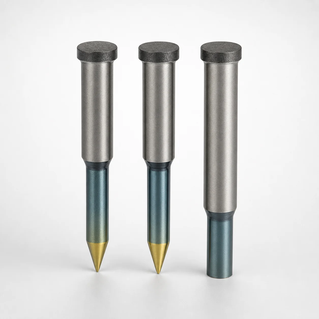
Powdered High-Speed Steel Round Stopper Punches Single-Stepped
Powdered high-speed steel round stopper punches use a single-stepped shank with a flange stopper for reliable part positioning and consistent stopping performance in mold and die operations. Optional WPC treatment with DLC foundation supports improved surface durability.
- Single-stepped shank with flange stopper style maintains stable contact during cycling
- Made from powdered high-speed steel for wear resistance in stop-and-locate applications
- Supports tight shank diameter control with +0.005/0 tolerance reference for stable fit
- Available surface options include DLC foundation / WPC treatment for enhanced tool life
Specifications
456 configurations available
| Surface Treatment | D (Shank diameter) (mm) | P (Tip dimension) (mm) | L (L dimension) (mm) | B (Tip length) (mm) | BC (Tip length change) (mm) | LC (Full length alteration) (mm) | LCT (Head thickness tolerance change + Total length alteration) (mm) | T (Head length) (mm) | TC (T dimension alteration) (mm) | type |
|---|---|---|---|---|---|---|---|---|---|---|
| Without DLC foundation | 4 | 0.5 ~ 2 | 40 ~ 50 | 2 ~ 6 | - | - | - | 13 ~ 25 | - | - |
| Without DLC foundation | 4 | 0.5 ~ 2 | 40 ~ 50 | - | 2.1 ~ 40 | - | - | 13 ~ 25 | - | - |
| Without DLC foundation | 4 | 0.5 ~ 2 | 40 ~ 50 | 2 ~ 6 | - | - | - | - | 13.1 ~ 24.9 | - |
| Without DLC foundation | 4 | 0.5 ~ 2 | 40 ~ 50 | - | 2.1 ~ 40 | - | - | - | 13.1 ~ 24.9 | - |
| Without DLC foundation | 4 | 0.5 ~ 2 | - | 2 ~ 6 | - | 40 ~ 50 | - | 13 ~ 25 | - | - |
| Without DLC foundation | 4 | 0.5 ~ 2 | - | - | 2.1 ~ 40 | 40 ~ 50 | - | 13 ~ 25 | - | - |
| Without DLC foundation | 4 | 0.5 ~ 2 | - | 2 ~ 6 | - | 40 ~ 50 | - | - | 13.1 ~ 24.9 | - |
| Without DLC foundation | 4 | 0.5 ~ 2 | - | - | 2.1 ~ 40 | 40 ~ 50 | - | - | 13.1 ~ 24.9 | - |
| Without DLC foundation | 4 | 0.5 ~ 2 | - | 2 ~ 6 | - | - | 40 ~ 50 | 13 ~ 25 | - | - |
| Without DLC foundation | 4 | 0.5 ~ 2 | - | - | 2.1 ~ 40 | - | 40 ~ 50 | 13 ~ 25 | - | - |
| Without DLC foundation | 4 | 0.5 ~ 2 | - | 2 ~ 6 | - | - | 40 ~ 50 | - | 13.1 ~ 24.9 | - |
| Without DLC foundation | 4 | 0.5 ~ 2 | - | - | 2.1 ~ 40 | - | 40 ~ 50 | - | 13.1 ~ 24.9 | - |
| Without DLC foundation | 5 | 1 ~ 3 | 40 ~ 60 | 2 ~ 8 | - | - | - | 13 ~ 25 | - | - |
| Without DLC foundation | 5 | 1 ~ 3 | 40 ~ 60 | - | 2.1 ~ 40 | - | - | 13 ~ 25 | - | - |
| Without DLC foundation | 5 | 1 ~ 3 | 40 ~ 60 | 2 ~ 8 | - | - | - | - | 13.1 ~ 24.9 | - |
| Without DLC foundation | 5 | 1 ~ 3 | 40 ~ 60 | - | 2.1 ~ 40 | - | - | - | 13.1 ~ 24.9 | - |
| Without DLC foundation | 5 | 1 ~ 3 | - | 2 ~ 8 | - | 40 ~ 60 | - | 13 ~ 25 | - | - |
| Without DLC foundation | 5 | 1 ~ 3 | - | - | 2.1 ~ 40 | 40 ~ 60 | - | 13 ~ 25 | - | - |
| Without DLC foundation | 5 | 1 ~ 3 | - | 2 ~ 8 | - | 40 ~ 60 | - | - | 13.1 ~ 24.9 | - |
| Without DLC foundation | 5 | 1 ~ 3 | - | - | 2.1 ~ 40 | 40 ~ 60 | - | - | 13.1 ~ 24.9 | - |
| Without DLC foundation | 5 | 1 ~ 3 | - | 2 ~ 8 | - | - | 40 ~ 60 | 13 ~ 25 | - | - |
| Without DLC foundation | 5 | 1 ~ 3 | - | - | 2.1 ~ 40 | - | 40 ~ 60 | 13 ~ 25 | - | - |
| Without DLC foundation | 5 | 1 ~ 3 | - | 2 ~ 8 | - | - | 40 ~ 60 | - | 13.1 ~ 24.9 | - |
| Without DLC foundation | 5 | 1 ~ 3 | - | - | 2.1 ~ 40 | - | 40 ~ 60 | - | 13.1 ~ 24.9 | - |
| Without DLC foundation | 6 | 1.5 ~ 4 | 40 ~ 70 | 2 ~ 13 | - | - | - | 13 ~ 25 | - | - |
| Without DLC foundation | 6 | 1.5 ~ 4 | 40 ~ 70 | - | 2.1 ~ 40 | - | - | 13 ~ 25 | - | - |
| Without DLC foundation | 6 | 1.5 ~ 4 | 40 ~ 70 | 2 ~ 13 | - | - | - | - | 13.1 ~ 24.9 | - |
| Without DLC foundation | 6 | 1.5 ~ 4 | 40 ~ 70 | - | 2.1 ~ 40 | - | - | - | 13.1 ~ 24.9 | - |
| Without DLC foundation | 6 | 1.5 ~ 4 | - | 2 ~ 13 | - | 40 ~ 70 | - | 13 ~ 25 | - | - |
| Without DLC foundation | 6 | 1.5 ~ 4 | - | - | 2.1 ~ 40 | 40 ~ 70 | - | 13 ~ 25 | - | - |
| Without DLC foundation | 6 | 1.5 ~ 4 | - | 2 ~ 13 | - | 40 ~ 70 | - | - | 13.1 ~ 24.9 | - |
| Without DLC foundation | 6 | 1.5 ~ 4 | - | - | 2.1 ~ 40 | 40 ~ 70 | - | - | 13.1 ~ 24.9 | - |
| Without DLC foundation | 6 | 1.5 ~ 4 | - | 2 ~ 13 | - | - | 40 ~ 70 | 13 ~ 25 | - | - |
| Without DLC foundation | 6 | 1.5 ~ 4 | - | - | 2.1 ~ 40 | - | 40 ~ 70 | 13 ~ 25 | - | - |
| Without DLC foundation | 6 | 1.5 ~ 4 | - | 2 ~ 13 | - | - | 40 ~ 70 | - | 13.1 ~ 24.9 | - |
| Without DLC foundation | 6 | 1.5 ~ 4 | - | - | 2.1 ~ 40 | - | 40 ~ 70 | - | 13.1 ~ 24.9 | - |
| Without DLC foundation | 8 | 2 ~ 6 | 40 ~ 70 | 2 ~ 13 | - | - | - | 13 ~ 25 | - | - |
| Without DLC foundation | 8 | 2 ~ 6 | 40 ~ 70 | - | 2.1 ~ 40 | - | - | 13 ~ 25 | - | - |
| Without DLC foundation | 8 | 2 ~ 6 | 40 ~ 70 | 2 ~ 13 | - | - | - | - | 13.1 ~ 24.9 | - |
| Without DLC foundation | 8 | 2 ~ 6 | 40 ~ 70 | - | 2.1 ~ 40 | - | - | - | 13.1 ~ 24.9 | - |
| Without DLC foundation | 8 | 2 ~ 6 | - | 2 ~ 13 | - | 40 ~ 70 | - | 13 ~ 25 | - | - |
| Without DLC foundation | 8 | 2 ~ 6 | - | - | 2.1 ~ 40 | 40 ~ 70 | - | 13 ~ 25 | - | - |
| Without DLC foundation | 8 | 2 ~ 6 | - | 2 ~ 13 | - | 40 ~ 70 | - | - | 13.1 ~ 24.9 | - |
| Without DLC foundation | 8 | 2 ~ 6 | - | - | 2.1 ~ 40 | 40 ~ 70 | - | - | 13.1 ~ 24.9 | - |
| Without DLC foundation | 8 | 2 ~ 6 | - | 2 ~ 13 | - | - | 40 ~ 70 | 13 ~ 25 | - | - |
| Without DLC foundation | 8 | 2 ~ 6 | - | - | 2.1 ~ 40 | - | 40 ~ 70 | 13 ~ 25 | - | - |
| Without DLC foundation | 8 | 2 ~ 6 | - | 2 ~ 13 | - | - | 40 ~ 70 | - | 13.1 ~ 24.9 | - |
| Without DLC foundation | 8 | 2 ~ 6 | - | - | 2.1 ~ 40 | - | 40 ~ 70 | - | 13.1 ~ 24.9 | - |
| Without DLC foundation | 10 | 3 ~ 8 | 40 ~ 70 | 2 ~ 10 | - | - | - | 13 ~ 25 | - | - |
| Without DLC foundation | 10 | 3 ~ 8 | 40 ~ 70 | 11 ~ 13 | - | - | - | 13 ~ 25 | - | - |
Product Guide
Application Scenarios+
Single-stepped round stopper punches are used inside progressive dies and large mold tooling to provide repeatable stopping and part location during each press cycle. The flange stopper helps maintain stable contact as the punch advances and retracts, reducing variability that can affect downstream operations.
- Progressive die stopping for small parts: Choose shank diameters from 4–25 mm to match guide and clearance requirements, supporting consistent stop-and-locate indexing.
- Die-casting component tooling: In die-casting applications where cycle counts are high, the powdered high-speed steel base supports abrasion and wear resistance at the stopping interface.
- Surface durability upgrade: When adhesive or abrasive wear is a concern, the optional DLC foundation / WPC surface option improves tool surface durability for extended service life.
Material & Process Details+
This product is made from powdered high-speed steel (HSS), selected for wear resistance in stop-and-locate tooling where the punch repeatedly contacts the same surfaces. Powder metallurgy enables a dense, fine microstructure that supports stable cutting/impact performance under cycling loads.
- Surface treatment options: Offered in without DLC foundation or DLC foundation / WPC. The WPC option with a DLC foundation is intended to enhance surface durability and reduce wear at the contact region.
- Heat treatment state: The provided data specifies the material type and surface options, but does not list a specific hardness (HRC) value or exact quench-and-temper/nitriding recipe.
- Trade-offs: In general, harder surface treatments increase wear resistance, while the underlying HSS maintains toughness to better withstand repetitive load cycles.
Sizing & Selection Guide+
Select the stopper punch dimensions by matching the shank and tip geometry to the progressive die or mold cavity/core interface where stopping occurs. The design intent is to achieve stable guidance with controlled clearance, while the flange stopper ensures consistent contact during cycling.
- Choose shank diameter D: Available in 4–25 mm. Use the intended guide bore size and working clearance to select a diameter that maintains proper fit across expected wear.
- Match tip geometry: Tip dimension P ranges 0.5–13 mm, while tip length B is offered in multiple bands (e.g., 2–6, 2–8, 2–10, 2–13, and 11–13).
- Select overall length L: Offered as 40–50, 40–60, or 40–70 based on the available tool stack and required stroke.
- Tolerance/fit considerations: A reference fit tolerance is stated as +0.005/0 for shank diameter control; confirm final clearance with your guide/bushing specifications.
- Configurable vs fixed: Surface treatment is configurable (without DLC foundation / DLC foundation WPC); head thickness and related dimensions include fixed T = 13–25 with variable alteration ranges (TC, LC) depending on the chosen length set.
Frequently Asked Questions
Which surface treatment option should I choose for high-cycle progressive die stopper applications?+
For extended service life in abrasive or high-cycle stopping interfaces, select the DLC foundation / WPC option. If wear and adhesion are not severe or if you prefer a simpler surface condition, choose without DLC foundation. The base material remains powdered high-speed steel in both cases.
How do I select the shank diameter D to maintain proper fit in the die guide?+
Use the available shank diameter range of 4–25 mm to match your guide bore and desired clearance. The product description references shank diameter control with a +0.005/0 tolerance reference for stable fit. Verify final clearance against your bushing/guide specifications and account for wear over cycles.
What ranges should I consider for the tip geometry (P and B) when designing the stopping interface?+
Tip dimension P is available in 0.5–13 mm, and tip length B is offered in multiple bands such as 2–6, 2–8, 2–10, 2–13, and 11–13 (depending on the size set). Choose P to match contact area requirements and choose B to suit the available stopping depth and wear allowance.
How should I choose the overall length L for a given tool stack height?+
The product offers overall length L options of 40–50, 40–60, and 40–70. Use your tool stack height, required stand-off, and stroke to ensure the punch reaches the intended stopping position. Related alteration ranges (e.g., LC and LCT) align to the chosen length set.
Are the head dimensions fixed, and how do TC and TCT ranges affect compatibility?+
The head thickness/length parameter T is specified as 13–25 mm as fixed, while adjustment/alteration ranges are provided through TC (e.g., 13.1–24.9 and subranges) and LCT based on the selected L set (e.g., 40–50, 40–60, 40–70). Confirm these values against your recess/counterbore geometry to ensure assembly fit and adequate clearance.
Related Products

Need Custom Specifications?
Our engineering team can help with custom configurations, material selection, and volume pricing.