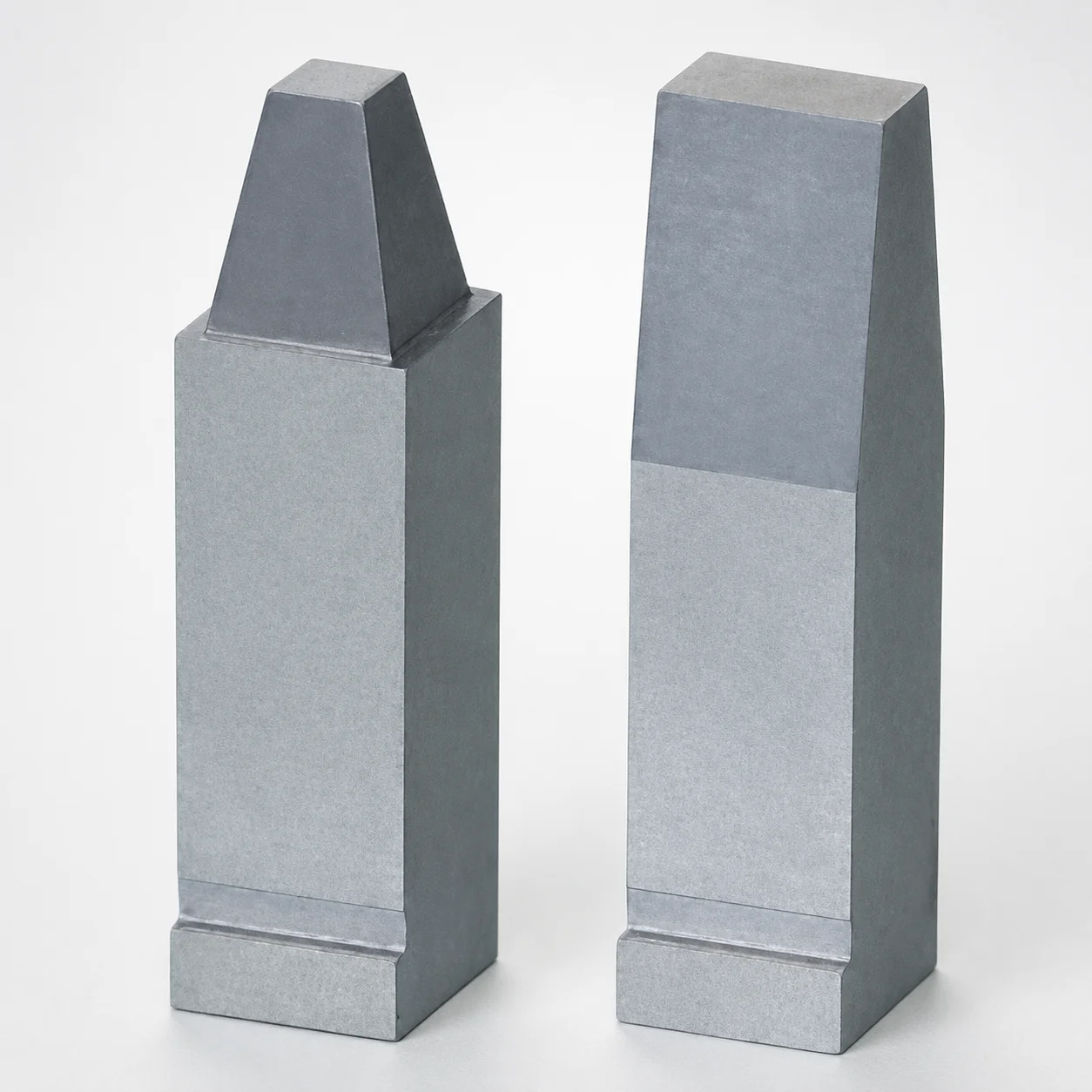
Steel Block Core Pins No-Tip with Flange
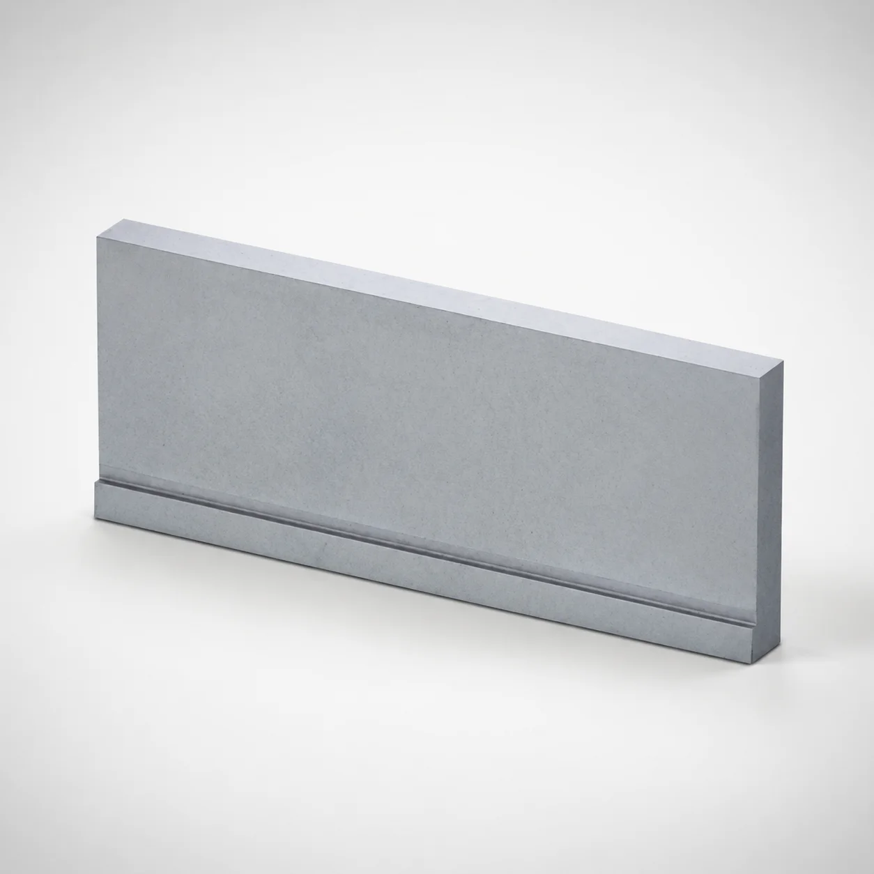
Block core pins no-tip with flange provide reliable positioning in mold block assemblies, using a positive flange feature to support stable fit during operation. Designed for controlled ejection alignment without a machined tip geometry.
- Flange-equipped mounting improves retention and assembly stability in mold blocks
- Hardened steel options support consistent wear resistance for long runs
- Eliminates R-chamfered positioning to keep the locating interface uniform
- Compatible with mold making workflows that require precise core pin placement
Specifications
70 configurations available
| Material | Tip Shape | F (Flange Position) (°) | Hardness | W (External shape) (mm) | A (Tip shape) (mm) | E (Tip shape) (mm) | H (Flange thickness) (mm) | J (Tip shape) (mm) | L (L dimension) (mm) | N (Length of straight section) (mm) | P (Outer diameter) (mm) | V (Tip shape) (mm) | type |
|---|---|---|---|---|---|---|---|---|---|---|---|---|---|
| ORVAR SUPREME | 1A | 0 ~ 270 | 51~53HRC | 1 ~ 20 | - | - | 4 ~ 6 | - | 20 ~ 70 | 10 ~ 70 | 1 ~ 20 | 0.5 ~ 20 | - |
| ORVAR SUPREME | 1B | 0 ~ 270 | 51~53HRC | 1 ~ 20 | - | 0.5 ~ 20 | 4 ~ 6 | - | 20 ~ 70 | 10 ~ 70 | 1 ~ 20 | - | - |
| ORVAR SUPREME | 2A | 0 ~ 270 | 51~53HRC | 1 ~ 20 | - | - | 4 ~ 6 | - | 20 ~ 70 | 10 ~ 70 | 1 ~ 20 | 0.5 ~ 20 | - |
| ORVAR SUPREME | 2B | 0 ~ 270 | 51~53HRC | 1 ~ 20 | - | 0.5 ~ 20 | 4 ~ 6 | 0.5 ~ 19.99 | 20 ~ 70 | 10 ~ 70 | 1 ~ 20 | - | - |
| ORVAR SUPREME | 3A | 0 ~ 270 | 51~53HRC | 1 ~ 20 | - | - | 4 ~ 6 | - | 20 ~ 70 | 10 ~ 70 | 1 ~ 20 | 0.5 ~ 20 | - |
| ORVAR SUPREME | 4A | 0 ~ 270 | 51~53HRC | 1 ~ 20 | - | - | 4 ~ 6 | - | 20 ~ 70 | 10 ~ 70 | 1 ~ 20 | 0.5 ~ 20 | - |
| ORVAR SUPREME | 5A | 0 ~ 270 | 51~53HRC | 1 ~ 20 | 0.5 ~ 20 | - | 4 ~ 6 | - | 20 ~ 70 | 10 ~ 70 | 1 ~ 20 | 0.5 ~ 20 | - |
| ORVAR SUPREME | 6A | 0 ~ 270 | 51~53HRC | 1 ~ 20 | 0.5 ~ 20 | - | 4 ~ 6 | - | 20 ~ 70 | 10 ~ 70 | 1 ~ 20 | 0.5 ~ 20 | - |
| ORVAR SUPREME | 7A | 0 ~ 270 | 51~53HRC | 1 ~ 20 | - | 0.5 ~ 20 | 4 ~ 6 | - | 20 ~ 70 | 10 ~ 70 | 1 ~ 20 | 0.5 ~ 20 | - |
| ORVAR SUPREME | 8A | 0 ~ 270 | 51~53HRC | 1 ~ 20 | - | 0.5 ~ 20 | 4 ~ 6 | - | 20 ~ 70 | 10 ~ 70 | 1 ~ 20 | 0.5 ~ 20 | - |
| ORVAR SUPREME | 9A | 0 ~ 270 | 51~53HRC | 1 ~ 20 | - | 0.5 ~ 20 | 4 ~ 6 | - | 20 ~ 70 | 10 ~ 70 | 1 ~ 20 | 0.5 ~ 20 | - |
| ORVAR SUPREME | 10A | 0 ~ 270 | 51~53HRC | 1 ~ 20 | - | 0.5 ~ 20 | 4 ~ 6 | - | 20 ~ 70 | 10 ~ 70 | 1 ~ 20 | 0.5 ~ 20 | - |
| ORVAR SUPREME | 11A | 0 ~ 270 | 51~53HRC | 1 ~ 20 | 0.5 ~ 20 | 0.5 ~ 20 | 4 ~ 6 | - | 20 ~ 70 | 10 ~ 70 | 1 ~ 20 | 0.5 ~ 20 | - |
| ORVAR SUPREME | 12A | 0 ~ 270 | 51~53HRC | 1 ~ 20 | 0.5 ~ 20 | 0.5 ~ 20 | 4 ~ 6 | 0.5 ~ 20 | 20 ~ 70 | 10 ~ 70 | 1 ~ 20 | 0.5 ~ 20 | - |
| SKH51 | 1A | 0 ~ 270 | 61~64HRC | 1 ~ 20 | - | - | 4 ~ 6 | - | 20 ~ 70 | 10 ~ 70 | 1 ~ 20 | 0.5 ~ 20 | - |
| SKH51 | 1B | 0 ~ 270 | 61~64HRC | 1 ~ 20 | - | 0.5 ~ 20 | 4 ~ 6 | - | 20 ~ 70 | 10 ~ 70 | 1 ~ 20 | - | - |
| SKH51 | 2A | 0 ~ 270 | 61~64HRC | 1 ~ 20 | - | - | 4 ~ 6 | - | 20 ~ 70 | 10 ~ 70 | 1 ~ 20 | 0.5 ~ 20 | - |
| SKH51 | 2B | 0 ~ 270 | 61~64HRC | 1 ~ 20 | - | 0.5 ~ 20 | 4 ~ 6 | 0.5 ~ 15.01 | 20 ~ 70 | 10 ~ 70 | 1 ~ 20 | - | - |
| SKH51 | 3A | 0 ~ 270 | 61~64HRC | 1 ~ 20 | - | - | 4 ~ 6 | - | 20 ~ 70 | 10 ~ 70 | 1 ~ 20 | 0.5 ~ 20 | - |
| SKH51 | 4A | 0 ~ 270 | 61~64HRC | 1 ~ 20 | - | - | 4 ~ 6 | - | 20 ~ 70 | 10 ~ 70 | 1 ~ 20 | 0.5 ~ 20 | - |
| SKH51 | 5A | 0 ~ 270 | 61~64HRC | 1 ~ 20 | 0.5 ~ 20 | - | 4 ~ 6 | - | 20 ~ 70 | 10 ~ 70 | 1 ~ 20 | 0.5 ~ 20 | - |
| SKH51 | 6A | 0 ~ 270 | 61~64HRC | 1 ~ 20 | 0.5 ~ 20 | - | 4 ~ 6 | - | 20 ~ 70 | 10 ~ 70 | 1 ~ 20 | 0.5 ~ 20 | - |
| SKH51 | 7A | 0 ~ 270 | 61~64HRC | 1 ~ 20 | - | 0.5 ~ 20 | 4 ~ 6 | - | 20 ~ 70 | 10 ~ 70 | 1 ~ 20 | 0.5 ~ 20 | - |
| SKH51 | 8A | 0 ~ 270 | 61~64HRC | 1 ~ 20 | - | 0.5 ~ 20 | 4 ~ 6 | - | 20 ~ 70 | 10 ~ 70 | 1 ~ 20 | 0.5 ~ 20 | - |
| SKH51 | 9A | 0 ~ 270 | 61~64HRC | 1 ~ 20 | - | 0.5 ~ 20 | 4 ~ 6 | - | 20 ~ 70 | 10 ~ 70 | 1 ~ 20 | 0.5 ~ 20 | - |
| SKH51 | 10A | 0 ~ 270 | 61~64HRC | 1 ~ 20 | - | 0.5 ~ 20 | 4 ~ 6 | - | 20 ~ 70 | 10 ~ 70 | 1 ~ 20 | 0.5 ~ 20 | - |
| SKH51 | 11A | 0 ~ 270 | 61~64HRC | 1 ~ 20 | 0.5 ~ 20 | 0.5 ~ 20 | 4 ~ 6 | - | 20 ~ 70 | 10 ~ 70 | 1 ~ 20 | 0.5 ~ 20 | - |
| SKH51 | 12A | 0 ~ 270 | 61~64HRC | 1 ~ 20 | 0.5 ~ 20 | 0.5 ~ 20 | 4 ~ 6 | 0.5 ~ 20 | 20 ~ 70 | 10 ~ 70 | 1 ~ 20 | 0.5 ~ 20 | - |
| NAK80 | 1A | 0 ~ 270 | 37~43HRC | 1 ~ 20 | - | - | 4 ~ 6 | - | 20 ~ 70 | 10 ~ 70 | 1 ~ 20 | 0.5 ~ 20 | - |
| NAK80 | 1B | 0 ~ 270 | 37~43HRC | 1 ~ 20 | - | 0.5 ~ 20 | 4 ~ 6 | - | 20 ~ 70 | 10 ~ 70 | 1 ~ 20 | - | - |
| NAK80 | 2A | 0 ~ 270 | 37~43HRC | 1 ~ 20 | - | - | 4 ~ 6 | - | 20 ~ 70 | 10 ~ 70 | 1 ~ 20 | 0.5 ~ 20 | - |
| NAK80 | 2B | 0 ~ 270 | 37~43HRC | 1 ~ 20 | - | 0.5 ~ 20 | 4 ~ 6 | 0.5 ~ 15.01 | 20 ~ 70 | 10 ~ 70 | 1 ~ 20 | - | - |
| NAK80 | 3A | 0 ~ 270 | 37~43HRC | 1 ~ 20 | - | - | 4 ~ 6 | - | 20 ~ 70 | 10 ~ 70 | 1 ~ 20 | 0.5 ~ 20 | - |
| NAK80 | 4A | 0 ~ 270 | 37~43HRC | 1 ~ 20 | - | - | 4 ~ 6 | - | 20 ~ 70 | 10 ~ 70 | 1 ~ 20 | 0.5 ~ 20 | - |
| NAK80 | 5A | 0 ~ 270 | 37~43HRC | 1 ~ 20 | 0.5 ~ 20 | - | 4 ~ 6 | - | 20 ~ 70 | 10 ~ 70 | 1 ~ 20 | 0.5 ~ 20 | - |
| NAK80 | 6A | 0 ~ 270 | 37~43HRC | 1 ~ 20 | 0.5 ~ 20 | - | 4 ~ 6 | - | 20 ~ 70 | 10 ~ 70 | 1 ~ 20 | 0.5 ~ 20 | - |
| NAK80 | 7A | 0 ~ 270 | 37~43HRC | 1 ~ 20 | - | 0.5 ~ 20 | 4 ~ 6 | - | 20 ~ 70 | 10 ~ 70 | 1 ~ 20 | 0.5 ~ 20 | - |
| NAK80 | 8A | 0 ~ 270 | 37~43HRC | 1 ~ 20 | - | 0.5 ~ 20 | 4 ~ 6 | - | 20 ~ 70 | 10 ~ 70 | 1 ~ 20 | 0.5 ~ 20 | - |
| NAK80 | 9A | 0 ~ 270 | 37~43HRC | 1 ~ 20 | - | 0.5 ~ 20 | 4 ~ 6 | - | 20 ~ 70 | 10 ~ 70 | 1 ~ 20 | 0.5 ~ 20 | - |
| NAK80 | 10A | 0 ~ 270 | 37~43HRC | 1 ~ 20 | - | 0.5 ~ 20 | 4 ~ 6 | - | 20 ~ 70 | 10 ~ 70 | 1 ~ 20 | 0.5 ~ 20 | - |
| NAK80 | 11A | 0 ~ 270 | 37~43HRC | 1 ~ 20 | 0.5 ~ 20 | 0.5 ~ 20 | 4 ~ 6 | - | 20 ~ 70 | 10 ~ 70 | 1 ~ 20 | 0.5 ~ 20 | - |
| NAK80 | 12A | 0 ~ 270 | 37~43HRC | 1 ~ 20 | 0.5 ~ 20 | 0.5 ~ 20 | 4 ~ 6 | 0.5 ~ 20 | 20 ~ 70 | 10 ~ 70 | 1 ~ 20 | 0.5 ~ 20 | - |
| RIGOR | 1A | 0 ~ 270 | 53~55HRC | 1 ~ 20 | - | - | 4 ~ 6 | - | 20 ~ 70 | 10 ~ 70 | 1 ~ 20 | 0.5 ~ 20 | - |
| RIGOR | 1B | 0 ~ 270 | 53~55HRC | 1 ~ 20 | - | 0.5 ~ 20 | 4 ~ 6 | - | 20 ~ 70 | 10 ~ 70 | 1 ~ 20 | - | - |
| RIGOR | 2A | 0 ~ 270 | 53~55HRC | 1 ~ 20 | - | - | 4 ~ 6 | - | 20 ~ 70 | 10 ~ 70 | 1 ~ 20 | 0.5 ~ 20 | - |
| RIGOR | 2B | 0 ~ 270 | 53~55HRC | 1 ~ 20 | - | 0.5 ~ 20 | 4 ~ 6 | 0.5 ~ 15.01 | 20 ~ 70 | 10 ~ 70 | 1 ~ 20 | - | - |
| RIGOR | 3A | 0 ~ 270 | 53~55HRC | 1 ~ 20 | - | - | 4 ~ 6 | - | 20 ~ 70 | 10 ~ 70 | 1 ~ 20 | 0.5 ~ 20 | - |
| RIGOR | 4A | 0 ~ 270 | 53~55HRC | 1 ~ 20 | - | - | 4 ~ 6 | - | 20 ~ 70 | 10 ~ 70 | 1 ~ 20 | 0.5 ~ 20 | - |
| RIGOR | 5A | 0 ~ 270 | 53~55HRC | 1 ~ 20 | 0.5 ~ 20 | - | 4 ~ 6 | - | 20 ~ 70 | 10 ~ 70 | 1 ~ 20 | 0.5 ~ 20 | - |
| RIGOR | 6A | 0 ~ 270 | 53~55HRC | 1 ~ 20 | 0.5 ~ 20 | - | 4 ~ 6 | - | 20 ~ 70 | 10 ~ 70 | 1 ~ 20 | 0.5 ~ 20 | - |
Product Guide
Application Scenarios+
These steel block core pins no-tip with a flange are used inside large die-casting mold tooling to ensure stable core positioning during repeated ejection cycles. The flange provides a positive locating support, helping the pin remain aligned through thermal cycles and mechanical load, which is especially valuable when a machined tip interface is undesirable.
Common scenarios include:
- Die-cast automotive component molds: the flange’s fixed thickness (H = 4–6 mm) supports secure retention in mold block assemblies, improving consistency of core alignment across high-run production.
- Industrial housing and bracket molds: the no-tip geometry reduces sensitivity to tip wear while keeping the locating interface uniform (avoiding R-chamfered positioning).
- Multi-block mold assemblies: variable tip shapes (up to Tip shape = 1–12) allow engineering match to the cavity/core layout while maintaining ejection alignment stability.
Hardened steel options are suited where wear resistance and dimensional stability matter in long production runs.
Material & Process Details+
This product is offered in several hardened steel options: ORVAR SUPREME, SKH51, NAK80, and RIGOR. The available hardness range spans 37–43 HRC, 47–49 HRC, 51–53 HRC, 53–55 HRC, and 61–64 HRC, enabling a selection based on the balance between wear resistance and toughness.
- Higher hardness (61–64 HRC) is typically selected for abrasive conditions to resist wear at the locating/working interface.
- Mid hardness (51–55 HRC) is often used when toughness and micro-chipping resistance are also critical.
- Lower hardness (37–43 HRC) can be beneficial where shock resistance and machining/fit considerations dominate.
Exact heat treatment state is not specified in the provided data; however, the listed hardness values indicate a hardened condition suitable for production mold service.
Sizing & Selection Guide+
To select the correct core pin size, match the pin’s working geometry to the receiving feature in your mold block layout. Use the fixed dimensional ranges to control fit and positioning: the outer diameter (P) is 1–20 mm, while the straight section length (N) is 10–70 mm and the overall L is 20–70 mm.
- Determine required insertion depth from your core layout, then choose L = 20–70 mm with N = 10–70 mm to maintain proper clearance and full engagement.
- Select P = 1–20 mm to match the locating bore/guiding pocket diameter tolerance class used in your mold blocks.
- Confirm the tip geometry requirements using Tip shape (1–12) and the tip dimensions: A, E = 0.5–20 mm and J, V = 0.5–19.99 mm / 0.5–20 mm / 0.5–15.01 mm depending on the selected tip shape.
The flange position F = 0–270° and flange thickness H = 4–6 mm should be set to align with assembly constraints in your specific mold block interface. If your design relies on close clearance, specify tight fit based on the P diameter and the receiving pocket tolerances used by your mold standards.
Frequently Asked Questions
Which material hardness should I choose for die-casting wear on flange-based core pin locating interfaces?+
How do I match flange position (F) and flange thickness (H) when assembling multi-block mold cores?+
What dimensional set is most critical for ensuring correct engagement: P, N, or L?+
How do the tip shape selections relate to tip geometry dimensions A, E, J, and V?+
Is this design intended to avoid the R-chamfered positioning interface—how does that affect locating uniformity?+
Related Products
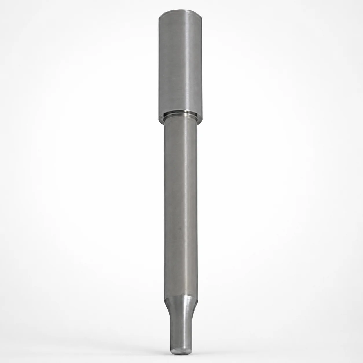
TiCN Option Powder High Speed Steel Round Stopper Punches Single-Stepped
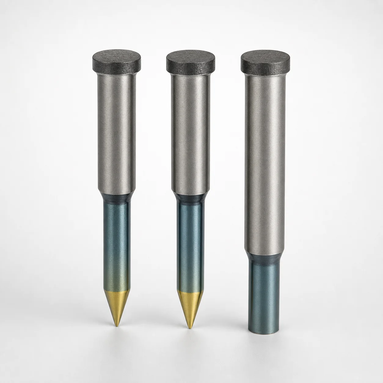
Powdered High-Speed Steel Round Stopper Punches Single-Stepped
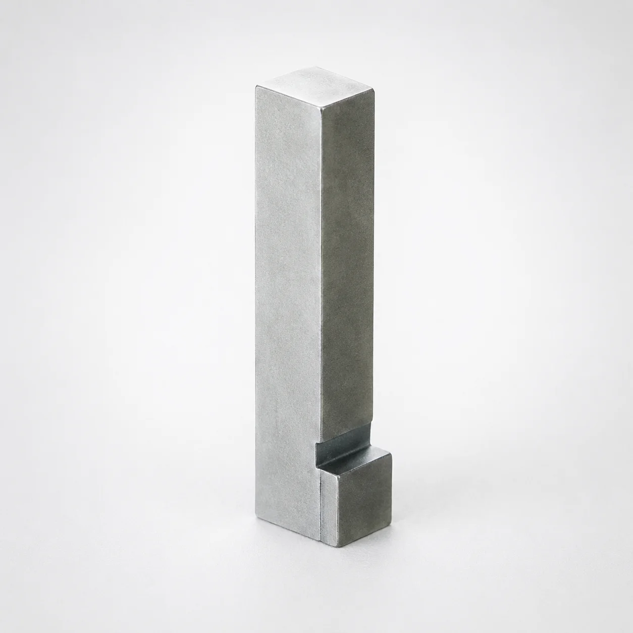
JIS Standard Steel Block Core Pins No Tip No Engraving
Block Core Pins No Tip Processing With Flange
JST PTFE Pipe Thread Seal Tapes

JMR Type Color Marker Rings for Water Flow Checkers
Need Custom Specifications?
Our engineering team can help with custom configurations, material selection, and volume pricing.