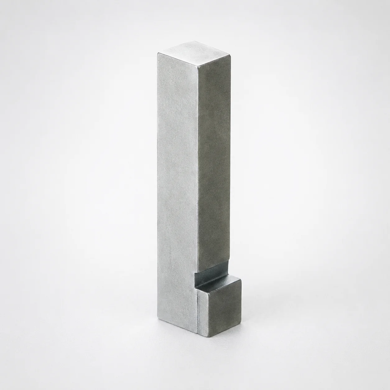
JIS Standard Steel Block Core Pins No Tip No Engraving
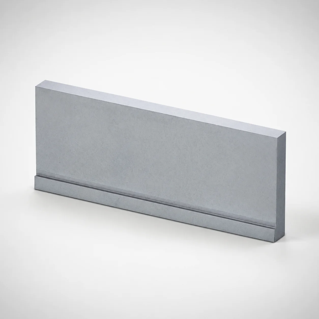
Block core pins no tip no engraving (SKH51 or NAK80 steel options) provide clean core support for mold blocks without tip processing or identification marks. The flange position is fixed at F = 0° to maintain consistent core alignment during assembly.
- No-tip design and no engraving characters help avoid interference and simplify core handling
- Steel core pin options with hardened construction support reliable wear resistance
- Supports controlled flange geometry with fixed F (flange position) = 0° for stable seating
- Suitable for injection molds using rectangular block cores with straight or flanged configurations
Specifications
48 configurations available
| Material | Includes Flange | R-Chamfered Position | F (Flange Position) (°) | Hardness | W (External shape) (mm) | H (Flange thickness) (mm) | HC (Changes the flange thickness) (mm) | L (L dimension) (mm) | P (Outer diameter) (mm) | R (Corner R) (mm) | type |
|---|---|---|---|---|---|---|---|---|---|---|---|
| SKH51 | Yes | 1AR | 0 | 61~64HRC | 1 ~ 20 | 4 ~ 6 | - | 10 ~ 70 | 1 ~ 20 | 0.1 ~ 0.2 | - |
| SKH51 | Yes | 1AR | 0 | 61~64HRC | 1 ~ 20 | - | 2.1 ~ 5.9 | 10 ~ 70 | 1 ~ 20 | 0.1 ~ 0.2 | - |
| SKH51 | Yes | 1BR | 0 | 61~64HRC | 1 ~ 20 | 4 ~ 6 | - | 10 ~ 70 | 1 ~ 20 | 0.1 ~ 0.2 | - |
| SKH51 | Yes | 1BR | 0 | 61~64HRC | 1 ~ 20 | - | 2.1 ~ 5.9 | 10 ~ 70 | 1 ~ 20 | 0.1 ~ 0.2 | - |
| SKH51 | Yes | 2AR | 0 | 61~64HRC | 1 ~ 20 | 4 ~ 6 | - | 10 ~ 70 | 1 ~ 20 | 0.1 ~ 0.2 | - |
| SKH51 | Yes | 2AR | 0 | 61~64HRC | 1 ~ 20 | - | 2 ~ 5.9 | 10 ~ 70 | 1 ~ 20 | 0.1 ~ 0.2 | - |
| SKH51 | Yes | 2BR | 0 | 61~64HRC | 1 ~ 20 | 4 ~ 6 | - | 10 ~ 70 | 1 ~ 20 | 0.1 ~ 0.2 | - |
| SKH51 | Yes | 2BR | 0 | 61~64HRC | 1 ~ 20 | - | 2 ~ 5.9 | 10 ~ 70 | 1 ~ 20 | 0.1 ~ 0.2 | - |
| SKH51 | Yes | 2CR | 0 | 61~64HRC | 1 ~ 20 | 4 ~ 6 | - | 10 ~ 70 | 1 ~ 20 | 0.1 ~ 0.2 | - |
| SKH51 | Yes | 2CR | 0 | 61~64HRC | 1 ~ 20 | - | 2.1 ~ 5.9 | 10 ~ 70 | 1 ~ 20 | 0.1 ~ 0.2 | - |
| SKH51 | Yes | 2DR | 0 | 61~64HRC | 1 ~ 20 | 4 ~ 6 | - | 10 ~ 70 | 1 ~ 20 | 0.1 ~ 0.2 | - |
| SKH51 | Yes | 2DR | 0 | 61~64HRC | 1 ~ 20 | - | 2 ~ 5.9 | 10 ~ 70 | 1 ~ 20 | 0.1 ~ 0.2 | - |
| SKH51 | Yes | 3AR | 0 | 61~64HRC | 1 ~ 20 | 4 ~ 6 | - | 10 ~ 70 | 1 ~ 20 | 0.1 ~ 0.2 | - |
| SKH51 | Yes | 3AR | 0 | 61~64HRC | 1 ~ 20 | - | 2.1 ~ 5.9 | 10 ~ 70 | 1 ~ 20 | 0.1 ~ 0.2 | - |
| SKH51 | Yes | 3BR | 0 | 61~64HRC | 1 ~ 20 | 4 ~ 6 | - | 10 ~ 70 | 1 ~ 20 | 0.1 ~ 0.2 | - |
| SKH51 | Yes | 3BR | 0 | 61~64HRC | 1 ~ 20 | - | 2.1 ~ 5.9 | 10 ~ 70 | 1 ~ 20 | 0.1 ~ 0.2 | - |
| SKH51 | Yes | 4R | 0 | 61~64HRC | 1 ~ 20 | 4 ~ 6 | - | 10 ~ 70 | 1 ~ 20 | 0.1 ~ 0.2 | - |
| SKH51 | Yes | 4R | 0 | 61~64HRC | 1 ~ 20 | - | 2 ~ 5.9 | 10 ~ 70 | 1 ~ 20 | 0.1 ~ 0.2 | - |
| NAK80 | Yes | 1AR | 0 | 37~43HRC | 1 ~ 20 | 4 ~ 6 | - | 10 ~ 70 | 1 ~ 20 | 0.1 ~ 0.2 | - |
| NAK80 | Yes | 1AR | 0 | 37~43HRC | 1 ~ 20 | - | 2 ~ 5.9 | 10 ~ 70 | 1 ~ 20 | 0.1 ~ 0.2 | - |
| NAK80 | Yes | 1BR | 0 | 37~43HRC | 1 ~ 20 | 4 ~ 6 | - | 10 ~ 70 | 1 ~ 20 | 0.1 ~ 0.2 | - |
| NAK80 | Yes | 1BR | 0 | 37~43HRC | 1 ~ 20 | - | 2 ~ 5.9 | 10 ~ 70 | 1 ~ 20 | 0.1 ~ 0.2 | - |
| NAK80 | Yes | 2AR | 0 | 37~43HRC | 1 ~ 20 | 4 ~ 6 | - | 10 ~ 70 | 1 ~ 20 | 0.1 ~ 0.2 | - |
| NAK80 | Yes | 2AR | 0 | 37~43HRC | 1 ~ 20 | - | 2 ~ 5.9 | 10 ~ 70 | 1 ~ 20 | 0.1 ~ 0.2 | - |
| NAK80 | Yes | 2BR | 0 | 37~43HRC | 1 ~ 20 | 4 ~ 6 | - | 10 ~ 70 | 1 ~ 20 | 0.1 ~ 0.2 | - |
| NAK80 | Yes | 2BR | 0 | 37~43HRC | 1 ~ 20 | - | 2 ~ 5.9 | 10 ~ 70 | 1 ~ 20 | 0.1 ~ 0.2 | - |
| NAK80 | Yes | 2CR | 0 | 37~43HRC | 1 ~ 20 | 4 ~ 6 | - | 10 ~ 70 | 1 ~ 20 | 0.1 ~ 0.2 | - |
| NAK80 | Yes | 2CR | 0 | 37~43HRC | 1 ~ 20 | - | 2 ~ 5.9 | 10 ~ 70 | 1 ~ 20 | 0.1 ~ 0.2 | - |
| NAK80 | Yes | 2DR | 0 | 37~43HRC | 1 ~ 20 | 4 ~ 6 | - | 10 ~ 70 | 1 ~ 20 | 0.1 ~ 0.2 | - |
| NAK80 | Yes | 2DR | 0 | 37~43HRC | 1 ~ 20 | - | 2.1 ~ 5.9 | 10 ~ 70 | 1 ~ 20 | 0.1 ~ 0.2 | - |
| NAK80 | Yes | 3AR | 0 | 37~43HRC | 1 ~ 20 | 4 ~ 6 | - | 10 ~ 70 | 1 ~ 20 | 0.1 ~ 0.2 | - |
| NAK80 | Yes | 3AR | 0 | 37~43HRC | 1 ~ 20 | - | 2 ~ 5.9 | 10 ~ 70 | 1 ~ 20 | 0.1 ~ 0.2 | - |
| NAK80 | Yes | 3BR | 0 | 37~43HRC | 1 ~ 20 | 4 ~ 6 | - | 10 ~ 70 | 1 ~ 20 | 0.1 ~ 0.2 | - |
| NAK80 | Yes | 3BR | 0 | 37~43HRC | 1 ~ 20 | - | 2.1 ~ 5.9 | 10 ~ 70 | 1 ~ 20 | 0.1 ~ 0.2 | - |
| NAK80 | Yes | 4R | 0 | 37~43HRC | 1 ~ 20 | 4 ~ 6 | - | 10 ~ 70 | 1 ~ 20 | 0.1 ~ 0.2 | - |
| NAK80 | Yes | 4R | 0 | 37~43HRC | 1 ~ 20 | - | 2 ~ 5.9 | 10 ~ 70 | 1 ~ 20 | 0.1 ~ 0.2 | - |
| NAK80 | No | 1AR | - | 37~43HRC | 1 ~ 20 | - | - | 10 ~ 70 | 1 ~ 20 | 0.1 ~ 0.2 | - |
| NAK80 | No | 2AR | - | 37~43HRC | 1 ~ 20 | - | - | 10 ~ 70 | 1 ~ 20 | 0.1 ~ 0.2 | - |
| NAK80 | No | 2BR | - | 37~43HRC | 1 ~ 20 | - | - | 10 ~ 70 | 1 ~ 20 | 0.1 ~ 0.2 | - |
| NAK80 | No | 2CR | - | 37~43HRC | 1 ~ 20 | - | - | 10 ~ 70 | 1 ~ 20 | 0.1 ~ 0.2 | - |
| NAK80 | No | 3AR | - | 37~43HRC | 1 ~ 20 | - | - | 10 ~ 70 | 1 ~ 20 | 0.1 ~ 0.2 | - |
| NAK80 | No | 4R | - | 37~43HRC | 1 ~ 20 | - | - | 10 ~ 70 | 1 ~ 20 | 0.1 ~ 0.2 | - |
| SKH51 | No | 1AR | - | 61~64HRC | 1 ~ 20 | - | - | 10 ~ 70 | 1 ~ 20 | 0.1 ~ 0.2 | - |
| SKH51 | No | 2AR | - | 61~64HRC | 1 ~ 20 | - | - | 10 ~ 70 | 1 ~ 20 | 0.1 ~ 0.2 | - |
| SKH51 | No | 2BR | - | 61~64HRC | 1 ~ 20 | - | - | 10 ~ 70 | 1 ~ 20 | 0.1 ~ 0.2 | - |
| SKH51 | No | 2CR | - | 61~64HRC | 1 ~ 20 | - | - | 10 ~ 70 | 1 ~ 20 | 0.1 ~ 0.2 | - |
| SKH51 | No | 3AR | - | 61~64HRC | 1 ~ 20 | - | - | 10 ~ 70 | 1 ~ 20 | 0.1 ~ 0.2 | - |
| SKH51 | No | 4R | - | 61~64HRC | 1 ~ 20 | - | - | 10 ~ 70 | 1 ~ 20 | 0.1 ~ 0.2 | - |
Product Guide
Application Scenarios+
These block core pins are used as precision core-support components in injection and die-casting mold tooling where clean core seating is critical. With the flange position set to F = 0°, they help maintain consistent alignment between the mold block and mating parts during assembly and repeated clamping cycles.
- Automotive and electronics insert molds: The no-tip, no-engraving configuration avoids interference with tight-fitting rectangular core blocks and simplifies handling where identification marks could contact adjacent components.
- Large die-casting or insert molding blocks: Straight or flanged core designs benefit from the fixed flange geometry (H = 4–6 mm) and optional flange presence to stabilize core location under moderate wear conditions.
- Production molds needing durable core seating: Hardened steel variants (SKH51 or NAK80) support reliable wear resistance at the pin/block interface, reducing loosening or seating drift over long runs.
Choose this variant when you need controlled flange placement, minimal risk of machining interference, and hardened core support.
Material & Process Details+
This series is offered in SKH51 or NAK80 steel options for block core pin applications. SKH51 is typically selected for higher wear resistance; the provided hardness range is 61–64 HRC, which improves resistance to fretting and edge wear at the seating surface.
- SKH51 (high hardness option): Harder condition for increased wear resistance, with the trade-off of requiring good alignment and handling to avoid brittle chipping at small corner radii.
- NAK80 (lower hardness option): Provided hardness range 37–43 HRC, offering improved toughness characteristics compared with very hard grades while still providing durable core support.
Manufacturing typically uses precision block-pin machining to the specified profile, followed by appropriate heat treatment to reach the stated HRC targets for each material choice. Corner detail is constrained by the specified R = 0.1–0.2 mm, so maintaining the heat-treated dimensions is important for consistent seating fit.
Sizing & Selection Guide+
Correct sizing ensures stable core seating and prevents misalignment caused by flange geometry or corner mismatch. Use the fixed geometry parameters first: the flange position is fixed at F = 0°, the flange thickness H = 4–6 mm, and the outer profile width W = 1–20 mm. The pin overall length is L = 10–70 mm.
- Match outer diameter P: Select P = 1–20 mm to fit the mating bore for the rectangular block core support.
- Set corner radius R: Use the specified R = 0.1–0.2 mm to avoid interference at the seating transitions, especially when cavities are tightly packed.
- Chips/step control via R-chamfered position: Choose R-chamfered position = 1–4 to align chamfered transitions with the core/block edge contact points.
- Flange thickness variation (HC): If applicable to your configuration, select HC = 2.1–5.9 mm (or 2–5.9 mm depending on variant) to achieve the required seating height where the flange changes thickness.
Because hardness and fine radii affect fit stability, confirm mating features and tolerances on the core blocks before final assembly; sizes above are fixed ranges and should be treated as variant-specific, not interchangeable.
Frequently Asked Questions
Which steel grade should I choose between SKH51 and NAK80 for block core pin seating wear?+
How does the fixed flange position F = 0° affect core alignment in mold block assembly?+
What dimensions in this pin should I verify first to prevent interference with rectangular block cores?+
How do I select the correct flange thickness characteristics (H and HC) for the required seating height?+
What role does the R-chamfered position (1–4) play during core support and assembly?+
Related Products
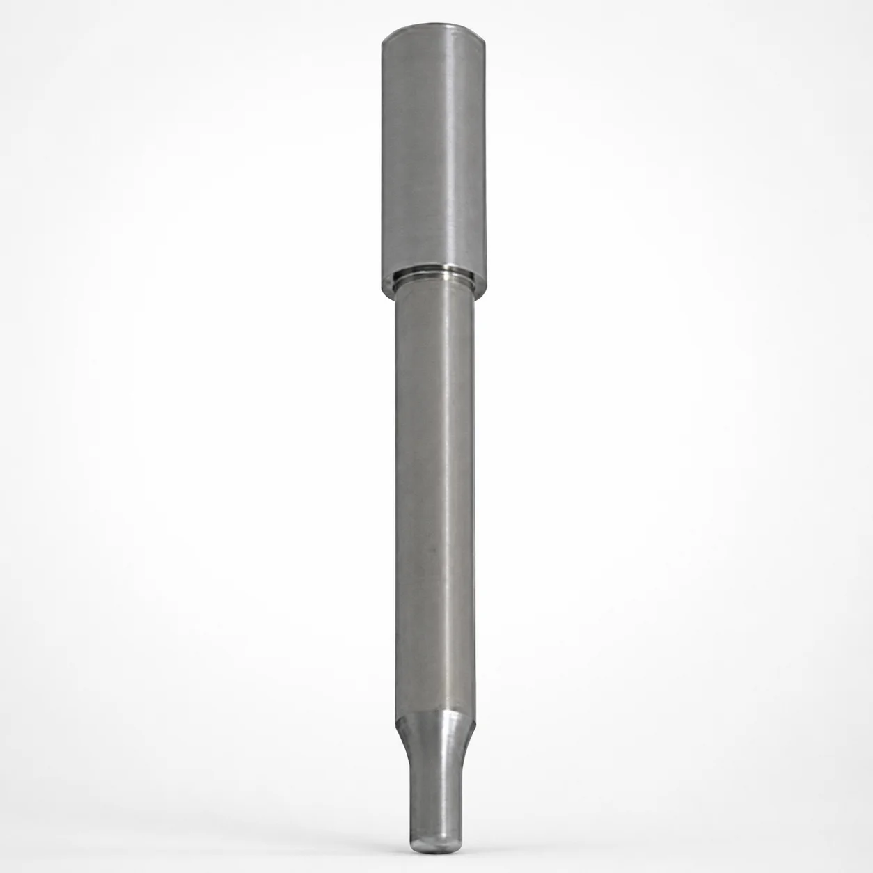
TiCN Option Powder High Speed Steel Round Stopper Punches Single-Stepped
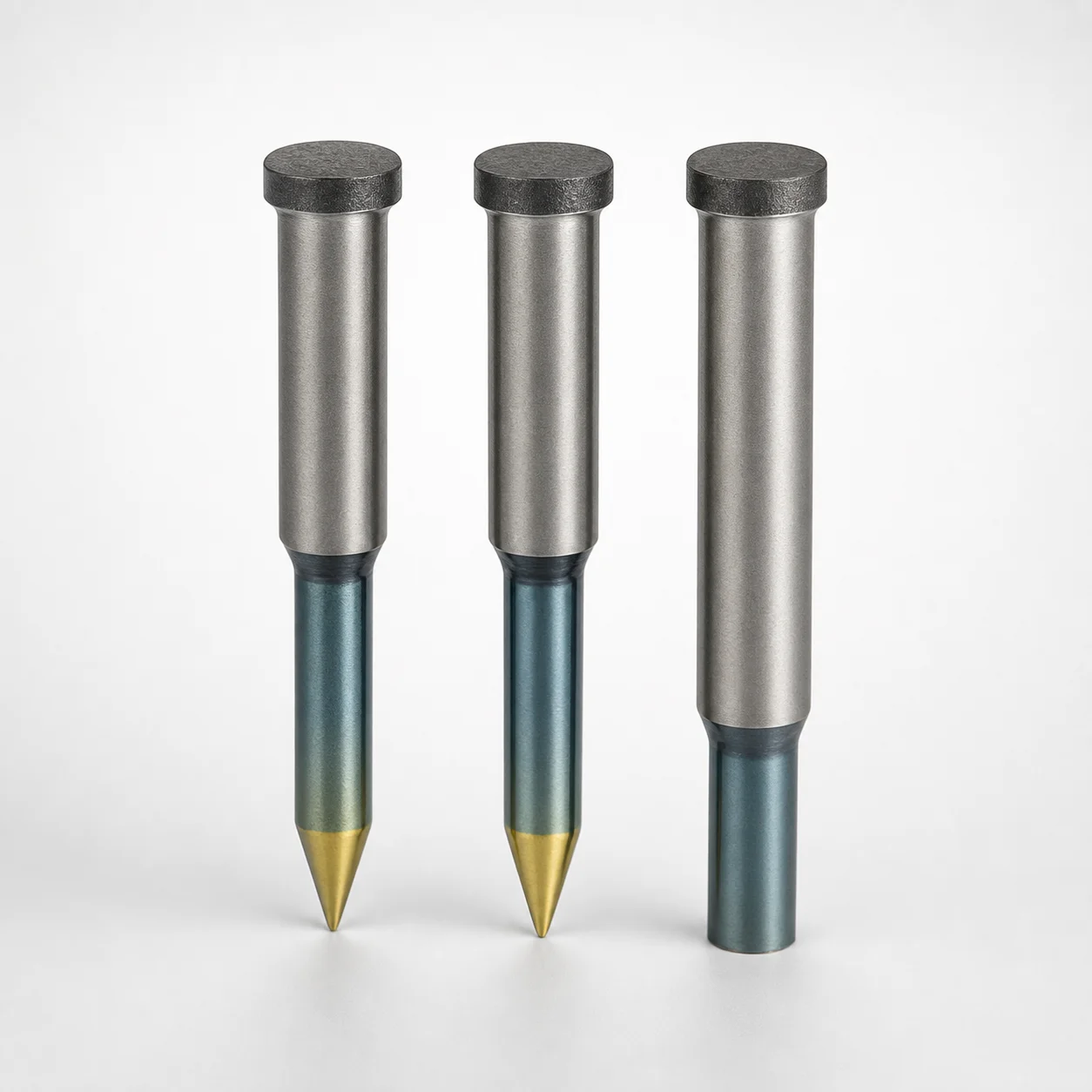
Powdered High-Speed Steel Round Stopper Punches Single-Stepped
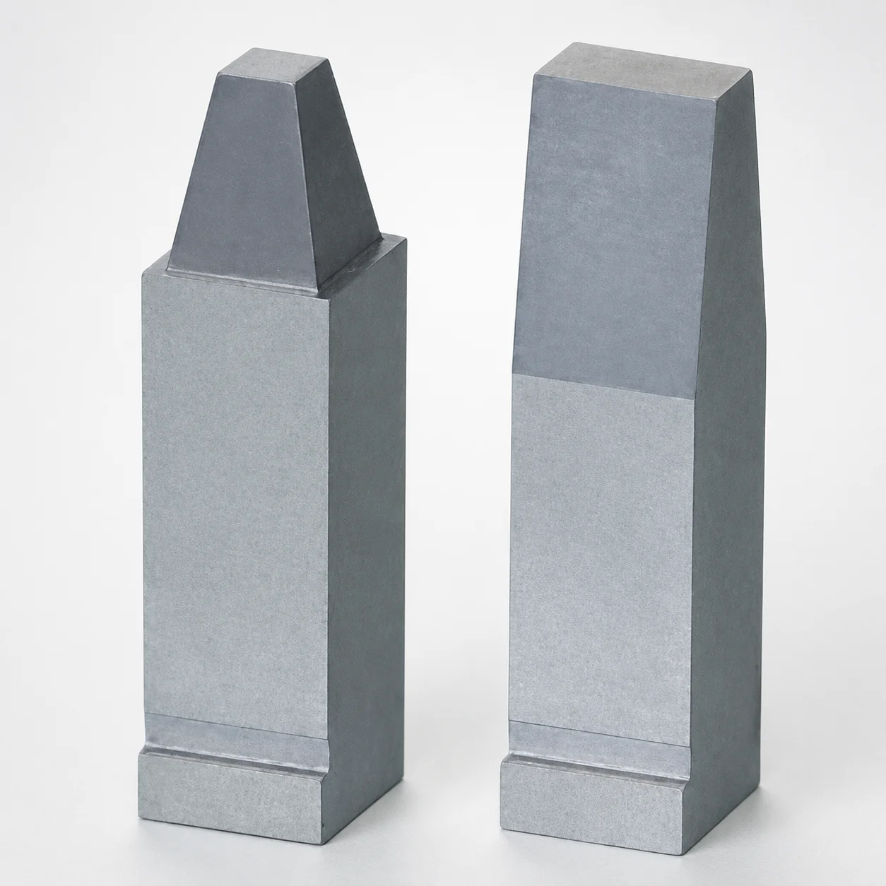
Steel Block Core Pins No-Tip with Flange
Block Core Pins No Tip Processing With Flange
JST PTFE Pipe Thread Seal Tapes
JMR Type Color Marker Rings for Water Flow Checkers
Need Custom Specifications?
Our engineering team can help with custom configurations, material selection, and volume pricing.