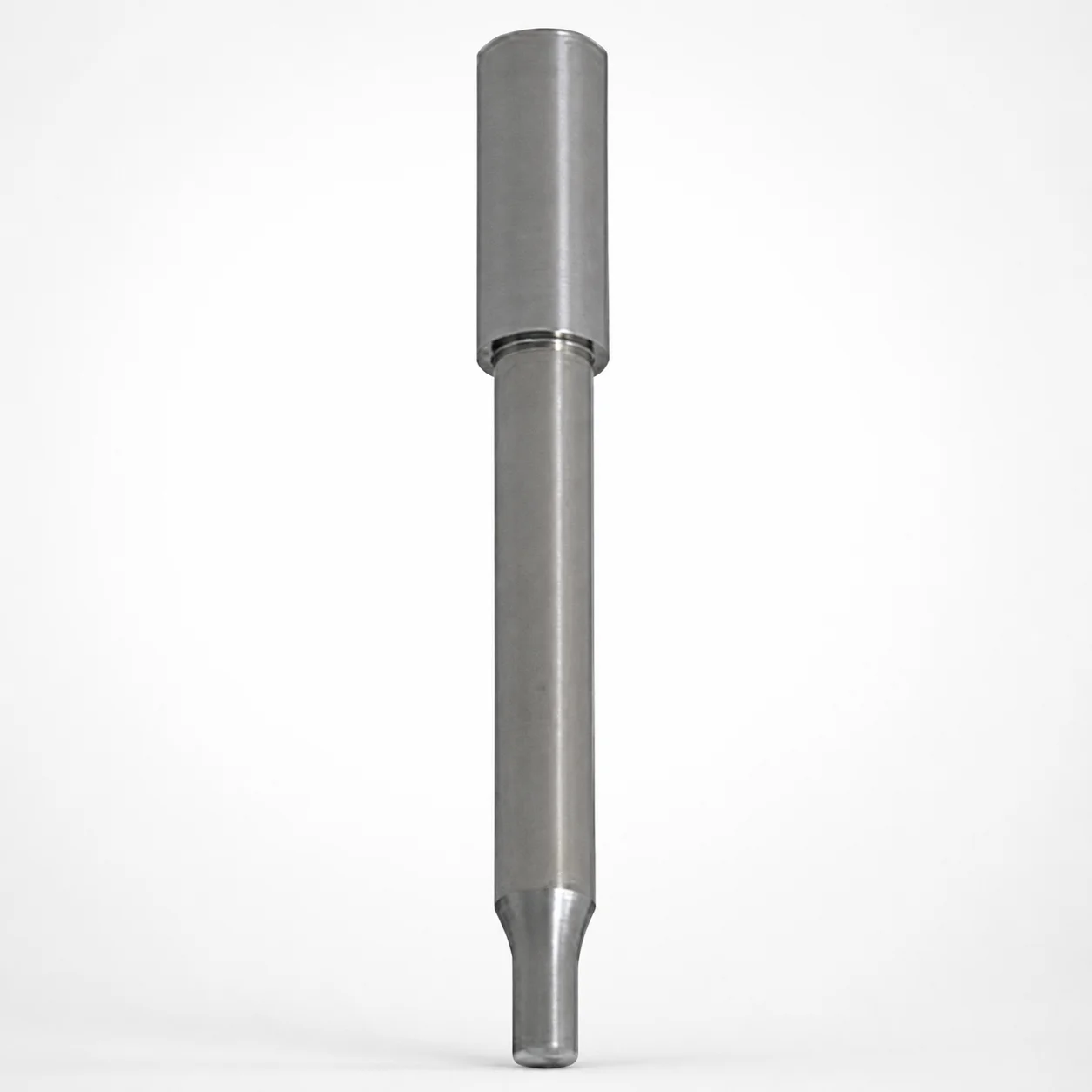
TiCN Option Powder High Speed Steel Round Stopper Punches Single-Stepped
Round stopper punches single-stepped (powder high-speed steel) provide a controlled stopping feature with a flange stopper mounting for reliable punch alignment in production. Optional TiCN surface treatment helps reduce wear during high-cycle forming.
- Single-stepped shank with flange stopper design improves seating consistency
- Powder high-speed steel construction supports stable cutting performance
- Shank diameter holds +0.005/0 to match tight locating requirements
- Used for round punching, stripping, and controlled part positioning in stamping tools
Specifications
456 configurations available
| Surface Treatment | D (Shank diameter) (mm) | P (Tip dimension) (mm) | L (L dimension) (mm) | B (Tip length) (mm) | BC (Tip length change) (mm) | LC (Full length alteration) (mm) | LCT (Head thickness tolerance change + Total length alteration) (mm) | T (Head length) (mm) | TC (T dimension alteration) (mm) | type |
|---|---|---|---|---|---|---|---|---|---|---|
| TiCN | 4 | 1 ~ 2 | 40 ~ 50 | 2 ~ 6 | - | - | - | 13 ~ 25 | - | - |
| TiCN | 4 | 1 ~ 2 | 40 ~ 50 | - | 2.1 ~ 40 | - | - | 13 ~ 25 | - | - |
| TiCN | 4 | 1 ~ 2 | 40 ~ 50 | 2 ~ 6 | - | - | - | - | 13.1 ~ 24.9 | - |
| TiCN | 4 | 1 ~ 2 | 40 ~ 50 | - | 2.1 ~ 40 | - | - | - | 13.1 ~ 24.9 | - |
| TiCN | 4 | 1 ~ 2 | - | 2 ~ 6 | - | 40 ~ 50 | - | 13 ~ 25 | - | - |
| TiCN | 4 | 1 ~ 2 | - | - | 2.1 ~ 40 | 40 ~ 50 | - | 13 ~ 25 | - | - |
| TiCN | 4 | 1 ~ 2 | - | 2 ~ 6 | - | 40 ~ 50 | - | - | 13.1 ~ 24.9 | - |
| TiCN | 4 | 1 ~ 2 | - | - | 2.1 ~ 40 | 40 ~ 50 | - | - | 13.1 ~ 24.9 | - |
| TiCN | 4 | 1 ~ 2 | - | 2 ~ 6 | - | - | 40 ~ 50 | 13 ~ 25 | - | - |
| TiCN | 4 | 1 ~ 2 | - | - | 2.1 ~ 40 | - | 40 ~ 50 | 13 ~ 25 | - | - |
| TiCN | 4 | 1 ~ 2 | - | 2 ~ 6 | - | - | 40 ~ 50 | - | 13.1 ~ 24.9 | - |
| TiCN | 4 | 1 ~ 2 | - | - | 2.1 ~ 40 | - | 40 ~ 50 | - | 13.1 ~ 24.9 | - |
| TiCN | 5 | 1 ~ 3 | 40 ~ 60 | 2 ~ 8 | - | - | - | 13 ~ 25 | - | - |
| TiCN | 5 | 1 ~ 3 | 40 ~ 60 | - | 2.1 ~ 40 | - | - | 13 ~ 25 | - | - |
| TiCN | 5 | 1 ~ 3 | 40 ~ 60 | 2 ~ 8 | - | - | - | - | 13.1 ~ 24.9 | - |
| TiCN | 5 | 1 ~ 3 | 40 ~ 60 | - | 2.1 ~ 40 | - | - | - | 13.1 ~ 24.9 | - |
| TiCN | 5 | 1 ~ 3 | - | 2 ~ 8 | - | 40 ~ 60 | - | 13 ~ 25 | - | - |
| TiCN | 5 | 1 ~ 3 | - | - | 2.1 ~ 40 | 40 ~ 60 | - | 13 ~ 25 | - | - |
| TiCN | 5 | 1 ~ 3 | - | 2 ~ 8 | - | 40 ~ 60 | - | - | 13.1 ~ 24.9 | - |
| TiCN | 5 | 1 ~ 3 | - | - | 2.1 ~ 40 | 40 ~ 60 | - | - | 13.1 ~ 24.9 | - |
| TiCN | 5 | 1 ~ 3 | - | 2 ~ 8 | - | - | 40 ~ 60 | 13 ~ 25 | - | - |
| TiCN | 5 | 1 ~ 3 | - | - | 2.1 ~ 40 | - | 40 ~ 60 | 13 ~ 25 | - | - |
| TiCN | 5 | 1 ~ 3 | - | 2 ~ 8 | - | - | 40 ~ 60 | - | 13.1 ~ 24.9 | - |
| TiCN | 5 | 1 ~ 3 | - | - | 2.1 ~ 40 | - | 40 ~ 60 | - | 13.1 ~ 24.9 | - |
| TiCN | 6 | 1.5 ~ 4 | 40 ~ 70 | 2 ~ 13 | - | - | - | 13 ~ 25 | - | - |
| TiCN | 6 | 1.5 ~ 4 | 40 ~ 70 | - | 2.1 ~ 40 | - | - | 13 ~ 25 | - | - |
| TiCN | 6 | 1.5 ~ 4 | 40 ~ 70 | 2 ~ 13 | - | - | - | - | 13.1 ~ 24.9 | - |
| TiCN | 6 | 1.5 ~ 4 | 40 ~ 70 | - | 2.1 ~ 40 | - | - | - | 13.1 ~ 24.9 | - |
| TiCN | 6 | 1.5 ~ 4 | - | 2 ~ 13 | - | 40 ~ 70 | - | 13 ~ 25 | - | - |
| TiCN | 6 | 1.5 ~ 4 | - | - | 2.1 ~ 40 | 40 ~ 70 | - | 13 ~ 25 | - | - |
| TiCN | 6 | 1.5 ~ 4 | - | 2 ~ 13 | - | 40 ~ 70 | - | - | 13.1 ~ 24.9 | - |
| TiCN | 6 | 1.5 ~ 4 | - | - | 2.1 ~ 40 | 40 ~ 70 | - | - | 13.1 ~ 24.9 | - |
| TiCN | 6 | 1.5 ~ 4 | - | 2 ~ 13 | - | - | 40 ~ 70 | 13 ~ 25 | - | - |
| TiCN | 6 | 1.5 ~ 4 | - | - | 2.1 ~ 40 | - | 40 ~ 70 | 13 ~ 25 | - | - |
| TiCN | 6 | 1.5 ~ 4 | - | 2 ~ 13 | - | - | 40 ~ 70 | - | 13.1 ~ 24.9 | - |
| TiCN | 6 | 1.5 ~ 4 | - | - | 2.1 ~ 40 | - | 40 ~ 70 | - | 13.1 ~ 24.9 | - |
| TiCN | 8 | 2 ~ 6 | 40 ~ 70 | 2 ~ 13 | - | - | - | 13 ~ 25 | - | - |
| TiCN | 8 | 2 ~ 6 | 40 ~ 70 | - | 2.1 ~ 40 | - | - | 13 ~ 25 | - | - |
| TiCN | 8 | 2 ~ 6 | 40 ~ 70 | 2 ~ 13 | - | - | - | - | 13.1 ~ 24.9 | - |
| TiCN | 8 | 2 ~ 6 | 40 ~ 70 | - | 2.1 ~ 40 | - | - | - | 13.1 ~ 24.9 | - |
| TiCN | 8 | 2 ~ 6 | - | 2 ~ 13 | - | 40 ~ 70 | - | 13 ~ 25 | - | - |
| TiCN | 8 | 2 ~ 6 | - | - | 2.1 ~ 40 | 40 ~ 70 | - | 13 ~ 25 | - | - |
| TiCN | 8 | 2 ~ 6 | - | 2 ~ 13 | - | 40 ~ 70 | - | - | 13.1 ~ 24.9 | - |
| TiCN | 8 | 2 ~ 6 | - | - | 2.1 ~ 40 | 40 ~ 70 | - | - | 13.1 ~ 24.9 | - |
| TiCN | 8 | 2 ~ 6 | - | 2 ~ 13 | - | - | 40 ~ 70 | 13 ~ 25 | - | - |
| TiCN | 8 | 2 ~ 6 | - | - | 2.1 ~ 40 | - | 40 ~ 70 | 13 ~ 25 | - | - |
| TiCN | 8 | 2 ~ 6 | - | 2 ~ 13 | - | - | 40 ~ 70 | - | 13.1 ~ 24.9 | - |
| TiCN | 8 | 2 ~ 6 | - | - | 2.1 ~ 40 | - | 40 ~ 70 | - | 13.1 ~ 24.9 | - |
| TiCN | 10 | 3 ~ 8 | 40 ~ 70 | 2 ~ 10 | - | - | - | 13 ~ 25 | - | - |
| TiCN | 10 | 3 ~ 8 | 40 ~ 70 | 11 ~ 13 | - | - | - | 13 ~ 25 | - | - |
Product Guide
Application Scenarios+
Round stopper punches with a single-stepped shank are used inside punching and forming assemblies where consistent stopping and positioning are required. The flange stopper mounting and stepped geometry help maintain repeatable seating, reducing misalignment during high-cycle production.
- Automotive and industrial connector punching: suited for round blanking/positioning steps that must stop cleanly and repeatably, especially when the punch is guided by a locating flange.
- Electrical terminal or sheet metal forming tools: the powder high-speed steel base supports stable cutting performance while the optional TiCN surface treatment helps reduce abrasive and adhesive wear under frequent cycles.
- General stamping strip-and-hold operations: used to control stripping and part positioning by providing a defined stopping point in the tool stack.
Choose the TiCN option when your process emphasizes wear resistance and longer service intervals; choose no coating when you prioritize base material performance and cost optimization.
Material & Process Details+
This punch is made from powder high-speed steel, selected for balanced hardness and cutting stability in punching applications. Powder metallurgy improves uniformity and can enhance wear resistance compared with conventional cast HSS grades.
- Optional TiCN surface treatment: applied to improve wear resistance and reduce surface degradation during high-cycle forming. The coated surface generally increases abrasion resistance, supporting longer tooling life.
- Heat-treatment state: the provided data specifies the base material system (powder HSS) and the availability of TiCN or no coating; specific hardness (HRC) and exact heat-treatment schedule are not given in the input.
- Trade-off considerations: TiCN typically improves wear performance, while the base powder HSS retains toughness for reliable cutting under intermittent loads.
For comparison across variants, the key differentiator is the surface treatment (TiCN vs. none) rather than the core steel chemistry in the supplied specifications.
Sizing & Selection Guide+
Select dimensions by matching the punch stopping and locating needs to the die set and the cavity/core stack-up. The shank diameter D = 4 ~ 25 mm must fit the guide/bushing bore with the intended clearance for stable alignment; the listed shank diameter also indicates tight locating intent (+0.005 / 0 for shank diameter).
- Choose tip geometry: tip dimension P = 0.5 ~ 13 mm and tip length B from the available ranges (e.g., 2 ~ 6, 2 ~ 8, 2 ~ 13, 2 ~ 10, or 11 ~ 13 mm) to control penetration and stopping behavior.
- Set overall length/stack clearance: full length alteration LC = 40 ~ 50, 40 ~ 60, or 40 ~ 70 mm, and total length change windows aligned to L = 40 ~ 50, 40 ~ 60, or 40 ~ 70 mm options.
- Match head thickness/tolerance window: use TC ranges (13.1 ~ 24.9 mm with sub-ranges) and fixed BC = 2.1 ~ 40 mm to ensure seating depth and stop accuracy.
Confirm the tool stack clearance for T (head length) = 13 ~ 25 mm and the selected TC to prevent interference while ensuring a consistent stop.
Frequently Asked Questions
What is the functional difference between TiCN and the uncoated (None) option for these single-stepped stopper punches?+
The input specifies two surface treatment options: TiCN or None. TiCN is intended to improve wear resistance under high-cycle punching and forming, helping maintain stopping performance over longer production runs. The core material remains powder high-speed steel in both cases.
How do I choose the right shank diameter (D) to ensure proper alignment in the punch guide?+
Shank diameter D is available from 4 ~ 25 mm. The design intent includes tight locating guidance: +0.005 / 0 for the shank diameter, which should be matched to the guide/bushing bore clearance. Use this to prevent lateral movement that could affect stop consistency.
Which dimensions control the stopping position: P, B, L, or LC?+
Stopping behavior is primarily influenced by the tip geometry and overall stack: P (0.5 ~ 13 mm) defines the tip dimension, and B (e.g., 2 ~ 6, 2 ~ 8, 2 ~ 10, 2 ~ 13, or 11 ~ 13 mm) sets tip length. L and LC select the overall length variation windows (e.g., 40 ~ 50, 40 ~ 60, 40 ~ 70 mm) to ensure the flange stopper seats correctly in your tool stack.
How should I use TC and LCT to avoid interference and maintain repeatable seating?+
The specifications provide tolerance/alteration windows: LCT is listed for 40 ~ 50, 40 ~ 60, and 40 ~ 70 mm options, while TC ranges from 13.1 ~ 24.9 mm with sub-ranges. Match your selected TC and the chosen L/LC option to the die set height and bushing stack so the head length T (13 ~ 25 mm) does not bottom out or float.
Does BC remain fixed, and how does it relate to changing tip length and punch seating?+
The input lists BC as fixed: BC = 2.1 ~ 40 mm. This parameter is tied to the tip length change capability (while B defines the available tip length ranges). Select BC together with the target B and overall L/LC so the punch maintains the intended stopping depth with the flange stopper mounting.
Related Products

Need Custom Specifications?
Our engineering team can help with custom configurations, material selection, and volume pricing.