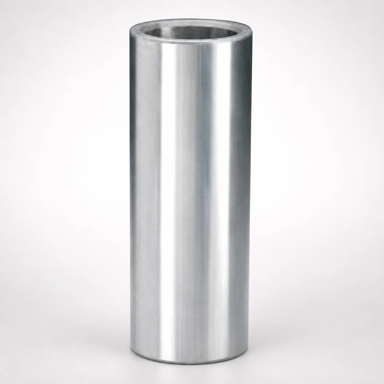
Steel Press-Fit Sleeve Bushings for Ball Guide Bearings
Steel press-fit sleeve bushings for ball guide bearings deliver a tight, repeatable fit to support controlled motion in die and bearing guide assemblies. As a bushing-only component, they simplify mounting and replacement during maintenance.
- Press-fit sleeve design improves alignment stability under guide load
- Steel construction with consistent material properties for reliable service life
- Metric range supports flexible selection for ball guide bushing applications
- Suitable for ball-guide bearing setups where a secure, interference fit is required
Specifications
109 configurations available
| Nom. Post Diameter (mm) | L (Length) (mm) |
|---|---|
| 19 | 100 |
| 19 | 110 |
| 19 | 125 |
| 19 | 150 |
| 19 | 50 |
| 19 | 55 |
| 19 | 65 |
| 19 | 70 |
| 19 | 75 |
| 19 | 80 |
| 19 | 90 |
| 19 | 95 |
| 25 | 100 |
| 25 | 105 |
| 25 | 115 |
| 25 | 120 |
| 25 | 125 |
| 25 | 140 |
| 25 | 150 |
| 25 | 165 |
| 25 | 175 |
| 25 | 75 |
| 25 | 80 |
| 25 | 90 |
| 25 | 95 |
| 32 | 100 |
| 32 | 105 |
| 32 | 115 |
| 32 | 125 |
| 32 | 140 |
| 32 | 150 |
| 32 | 165 |
| 32 | 175 |
| 32 | 200 |
| 32 | 230 |
| 32 | 75 |
| 32 | 80 |
| 32 | 90 |
| 32 | 95 |
| 40 | 100 |
| 40 | 105 |
| 40 | 115 |
| 40 | 120 |
| 40 | 125 |
| 40 | 135 |
| 40 | 140 |
| 40 | 150 |
| 40 | 165 |
| 40 | 175 |
| 40 | 190 |
Product Guide
Application Scenarios+
These steel press-fit sleeve bushings are used as bushing-only alignment components inside injection mold die sets and motion guide assemblies that incorporate ball guide bearings. The press-fit sleeve provides a tight, repeatable interference fit, helping maintain controlled motion and reducing micro-shift under load during production cycles.
In large-mold die-casting tooling, the bushing supports stable alignment for ball guide bearing guide columns, where repeated clamping and opening forces can otherwise wear or loosen guide interfaces. The consistent steel construction and tight press-fit help preserve alignment stability over maintenance intervals.
- Ball guide bearing guide assemblies: use the metric-ready sleeve to obtain a secure interference fit for controlled travel.
- High-cycle wear environments: the sleeve-only design simplifies replacement without redesigning the full guide module.
- Post/mount interfaces: match the sleeve OD to the post bore for reliable seating and repeatable alignment.
Material & Process Details+
For this product variant, the construction is steel, selected to deliver stable dimensional behavior and consistent mechanical performance in guided motion assemblies. In press-fit applications, steel’s combination of stiffness and toughness supports the interference seating process while resisting deformation during guide load.
- Hardness & wear: the exact HRC and heat-treatment state are not specified in the provided data, so selection should be validated against your guide-load and wear requirements.
- Toughness trade-off: higher surface hardness generally improves wear resistance but can reduce impact toughness; therefore, the bushing should be specified for the expected load and any shock events in die operations.
- Heat treatment: if your integration calls for enhanced wear, work with the supplier to confirm whether the sleeves are pre-hardened or quenched & tempered, and whether any surface treatment (e.g., nitriding) is applied.
When comparing material options (e.g., higher-alloy tool steels vs. standard steels), prioritize the balance between press-fit form stability, wear resistance under guide motion, and sufficient toughness for maintenance-related handling.
Sizing & Selection Guide+
Selection is driven by matching the sleeve to the nominal post diameter and the required sleeve length (L) for your ball guide bearing alignment assembly. Use the provided ranges: Nom. Post Diameter: 19 ~ 80 mm and L: 50 ~ 350 mm.
- Step 1—Match diameter: choose the nominal post diameter closest to the guide post size used in your die/bearing module. The sleeve must form the intended press-fit with the mating bore/post interface.
- Step 2—Match length: ensure the sleeve length supports the bearing guide engagement zone and provides adequate axial support for stable alignment during motion.
- Step 3—Tolerances & fit: press-fit performance depends on interference and the tolerances of both the sleeve OD and the mating bore/post. Confirm required interference/fit class within your drawing set, since the supplied data does not list specific tolerance values.
All listed dimensions are configurable within the stated ranges; verify the exact nominal size against the bearing guide geometry in your core/cavity tooling layout.
Frequently Asked Questions
How do I select the correct sleeve for a ball guide bearing guide post in a metric mold assembly?+
What sleeve length is typically needed for stable alignment under ball guide load?+
Does this bushing-only component replace the entire bearing guide unit, or only the worn interface?+
What steel properties should I verify for wear and press-fit reliability since no HRC is listed?+
What interference/fit tolerance should be used for the press-fit interface?+
Related Products
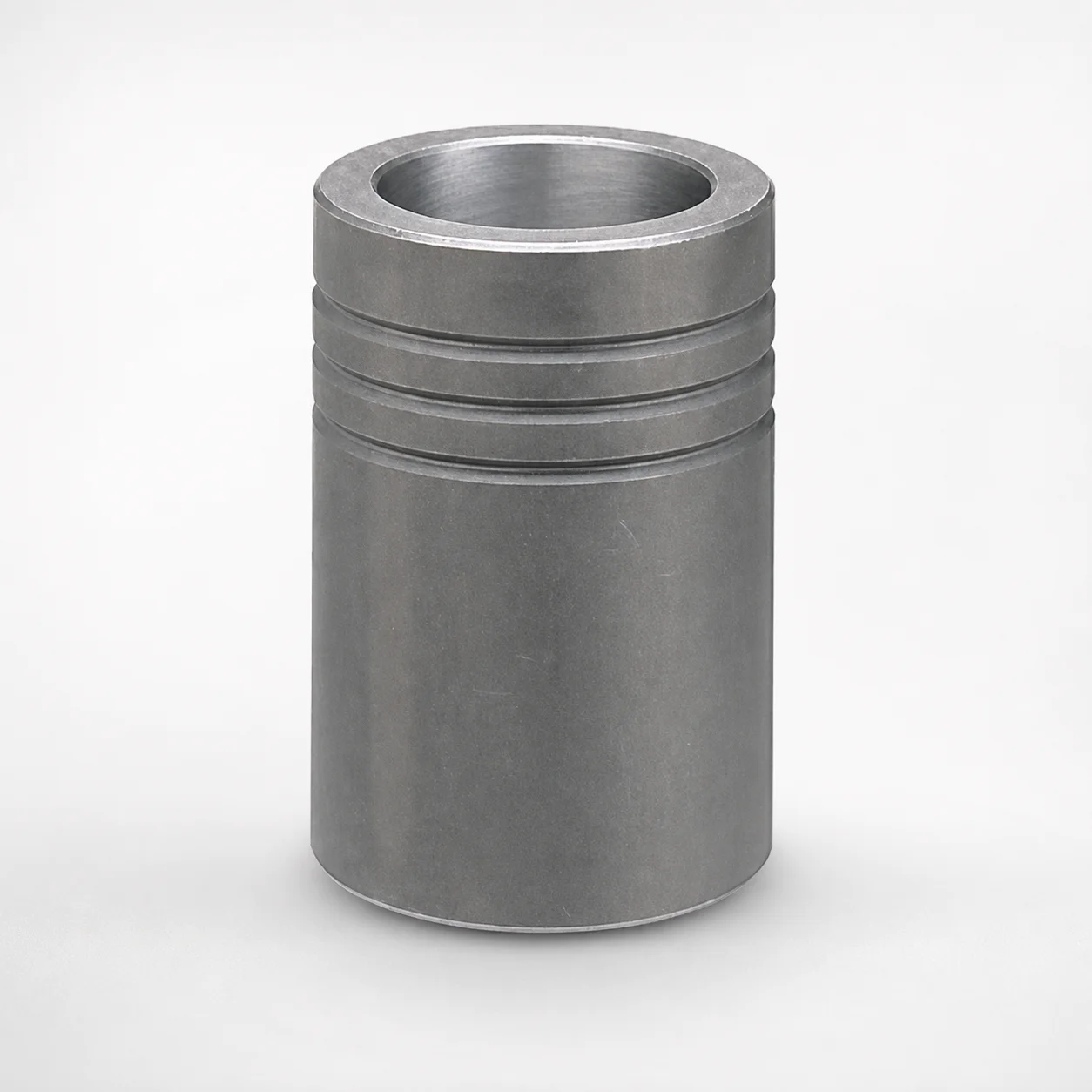
MBB Ball Guide Bushings for Die Sets Bonded by Devcon Adhesive
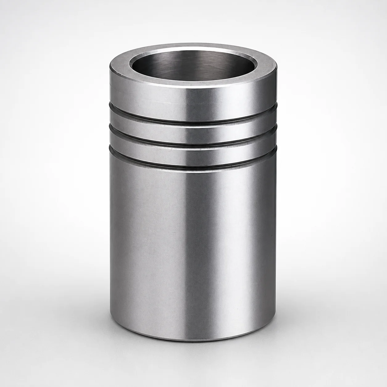
Ball Guide Bushings for Die Sets
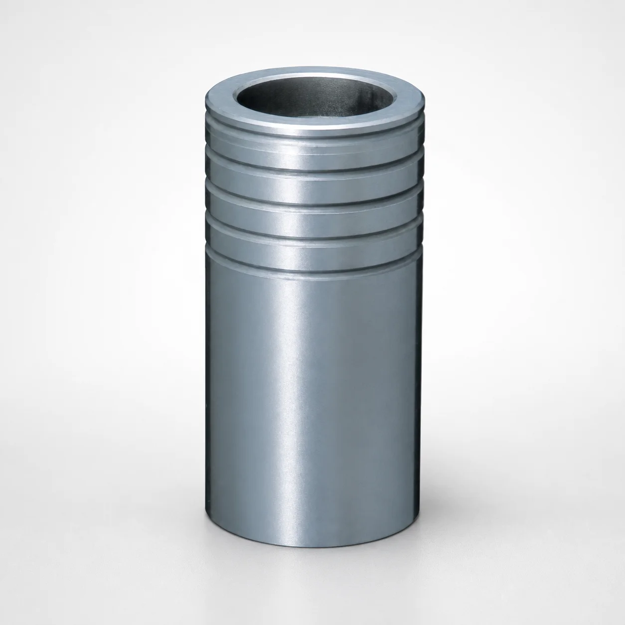
Ball Guide Bushings for Die Sets - Loctite Adhesive LBB Type
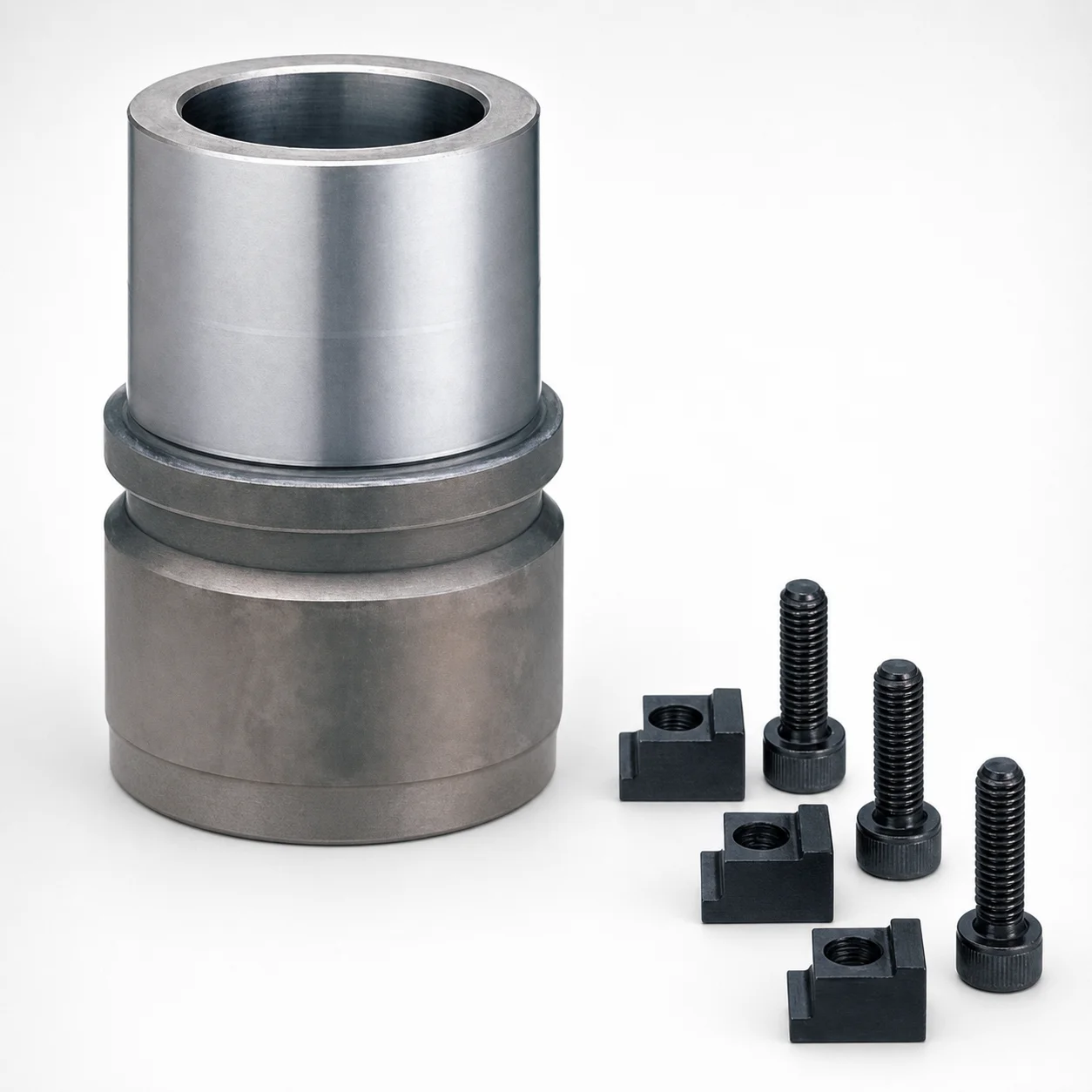
RBB Ball Guide Bushings for Die Sets - Detachable Type
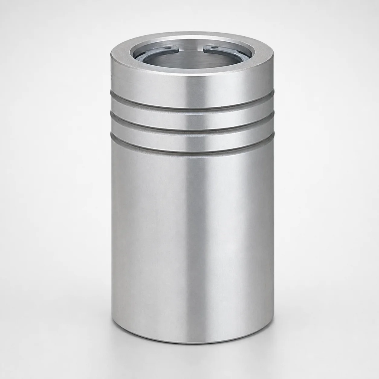
Ball Guide Bushings (LBBS) Loctite Bonded
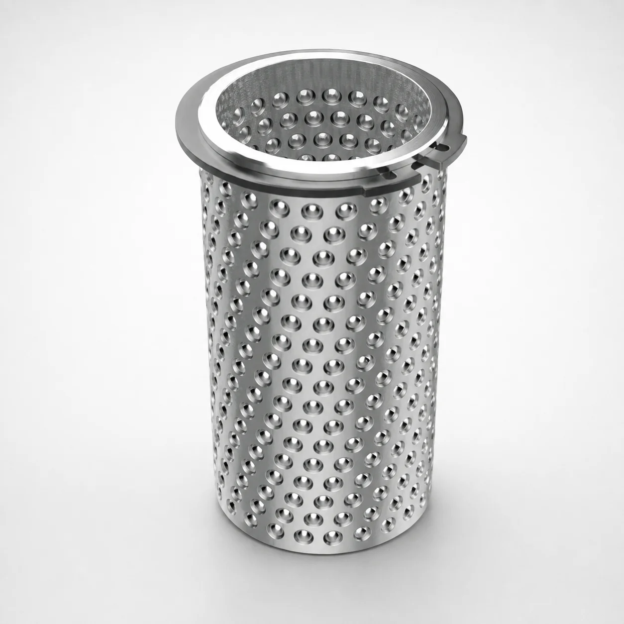
Aluminum Ball Cages for Guide Bushings with Groove & Circlip
Need Custom Specifications?
Our engineering team can help with custom configurations, material selection, and volume pricing.