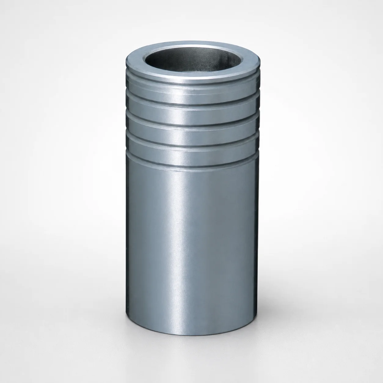
Ball Guide Bushings for Die Sets - Loctite Adhesive LBB Type
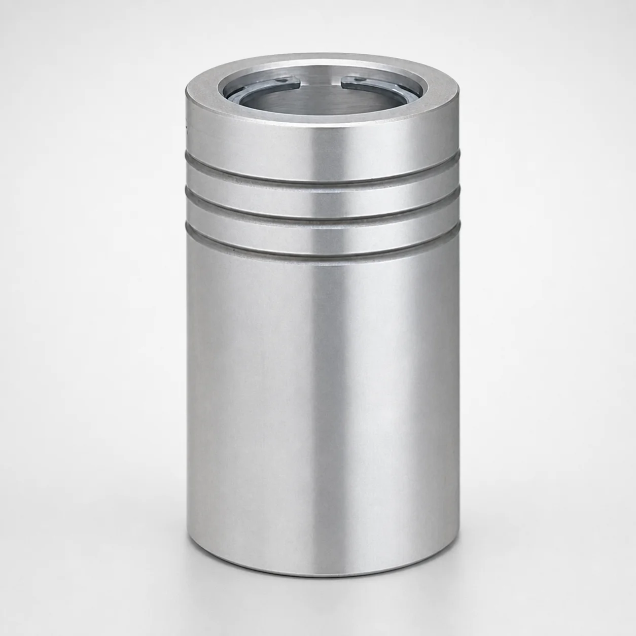
Ball guide bushings for die sets (LBB type) are designed as bushing-only components bonded with Loctite adhesive for reliable guidance inside die assemblies. They help maintain smooth, stable movement during repeated production cycles.
- Loctite adhesive mounting method supports consistent fit and retention
- Ball guide bushing type improves die set alignment for smoother motion
- Optimized for die set applications requiring stable positioning
- Available in multiple post diameter and length ranges for planning compatibility
Specifications
35 configurations available
| PD (Post diameter) (mm) | Length L (mm) | LC (L dimension) (mm) | type |
|---|---|---|---|
| 20 | 50 | - | - |
| 20 | - | 25 ~ 49 | - |
| 20 | - | 51 ~ 120 | - |
| 22 | 50 ~ 60 | - | - |
| 22 | - | 25 ~ 49 | - |
| 22 | - | 51 ~ 59 | - |
| 22 | - | 61 ~ 120 | - |
| 25 | 60 ~ 80 | - | - |
| 25 | - | 30 ~ 59 | - |
| 25 | - | 61 ~ 79 | - |
| 25 | - | 81 ~ 120 | - |
| 28 | 60 ~ 80 | - | - |
| 28 | - | 30 ~ 59 | - |
| 28 | - | 61 ~ 79 | - |
| 28 | - | 81 ~ 150 | - |
| 32 | 80 ~ 100 | - | - |
| 32 | - | 40 ~ 79 | - |
| 32 | - | 81 ~ 99 | - |
| 32 | - | 101 ~ 150 | - |
| 38 | 80 ~ 100 | - | - |
| 38 | - | 40 ~ 79 | - |
| 38 | - | 81 ~ 99 | - |
| 38 | - | 101 ~ 180 | - |
| 45 | 100 ~ 120 | - | - |
| 45 | - | 50 ~ 99 | - |
| 45 | - | 101 ~ 119 | - |
| 45 | - | 121 ~ 180 | - |
| 50 | 100 ~ 120 | - | - |
| 50 | - | 50 ~ 99 | - |
| 50 | - | 101 ~ 119 | - |
| 50 | - | 121 ~ 200 | - |
| 60 | 100 ~ 120 | - | - |
| 60 | - | 50 ~ 99 | - |
| 60 | - | 101 ~ 119 | - |
| 60 | - | 121 ~ 200 | - |
Product Guide
Application Scenarios+
Ball guide bushings (LBB type) are used as bushing-only guidance components inside die sets where the tooling must preserve alignment through repeated press cycles. The Loctite adhesive bonding approach helps lock the bushing in position reliably, reducing the risk of shifting under vibration or wear.
In automotive and large-part die casting systems, these bushings support smooth die set movement by improving localized guidance, which helps maintain consistent shut height and alignment during high-frequency operation.
They are also suited for industrial transfer and progressive die assemblies that require stable linear travel and repeatable motion across long runs. The bushing-only format allows you to integrate the component into an existing die design using the specified post diameter and length ranges.
- Adhesive retention supports consistent fit without mechanical-only holding.
- LBB guidance improves stability for smooth, repeatable die set motion.
Material & Process Details+
The provided product specifications define the LBB-type bushing geometry and mounting approach, including post diameter (PD) and length (L) ranges, but do not state a specific steel grade or heat-treatment process. Therefore, material hardness (HRC), wear resistance ratings, and any quench/temper or surface treatments (e.g., nitriding) cannot be confirmed from the supplied data.
What can be confirmed is the manufacturing concept: these bushings are designed for Loctite adhesive bonding, meaning the component must be compatible with adhesive mounting for secure retention under die set loads.
- Material selection: not provided—select based on your die set wear environment (sliding load, contamination, and cycle count) and confirm the supplier’s datasheet for the exact grade.
- Heat treatment: not provided—confirm any hardness target and trade-offs (higher hardness vs. toughness) from the material certificate.
Sizing & Selection Guide+
Select the ball guide bushing by matching post diameter (PD) and the installed length (L) to your die set guide features. The available PD range is 20 ~ 60 mm, and length options include 50 mm, 50 ~ 60 mm, 60 ~ 80 mm, 80 ~ 100 mm, and 100 ~ 120 mm.
Use LC (L dimension) to align with your die interface height requirements; the supplied LC range is 25 ~ 121 mm. When planning the cavity/core or die-mounting stack-up, ensure the bushing’s effective mounting length fits between adjacent guide surfaces with sufficient clearance for adhesive thickness and assembly variation.
- Core alignment: verify that PD matches the guide post feature diameter to avoid binding during die closure.
- Fit & retention: because mounting uses Loctite adhesive, consider adhesive application needs and confirm fit tolerances in your die assembly drawing/spec.
- Configurable dimensions: PD and L are range-based options; choose the bracket that covers your required values.
Frequently Asked Questions
How do I choose the correct PD (post diameter) for an LBB-type ball guide bushing in a die set?+
What L (length) and LC ranges should I verify to ensure proper die set stack-up clearance?+
Is this component intended to be used as a bushing-only guidance part (not a complete guide assembly)?+
How does Loctite adhesive bonding affect installation planning compared with mechanical retention?+
Can this bushing be selected for different die set guidance duty cycles based on material grade or hardness?+
Related Products
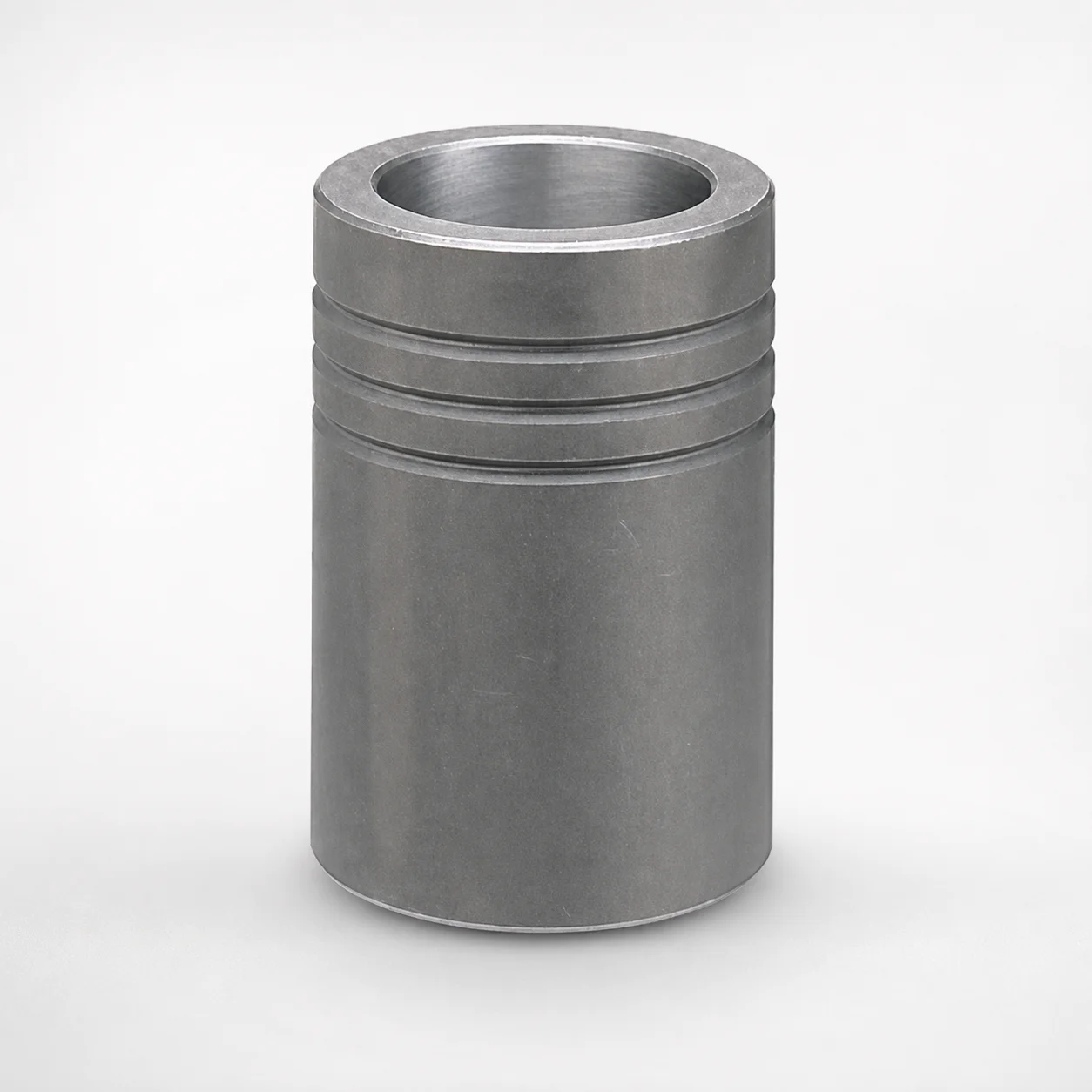
MBB Ball Guide Bushings for Die Sets Bonded by Devcon Adhesive
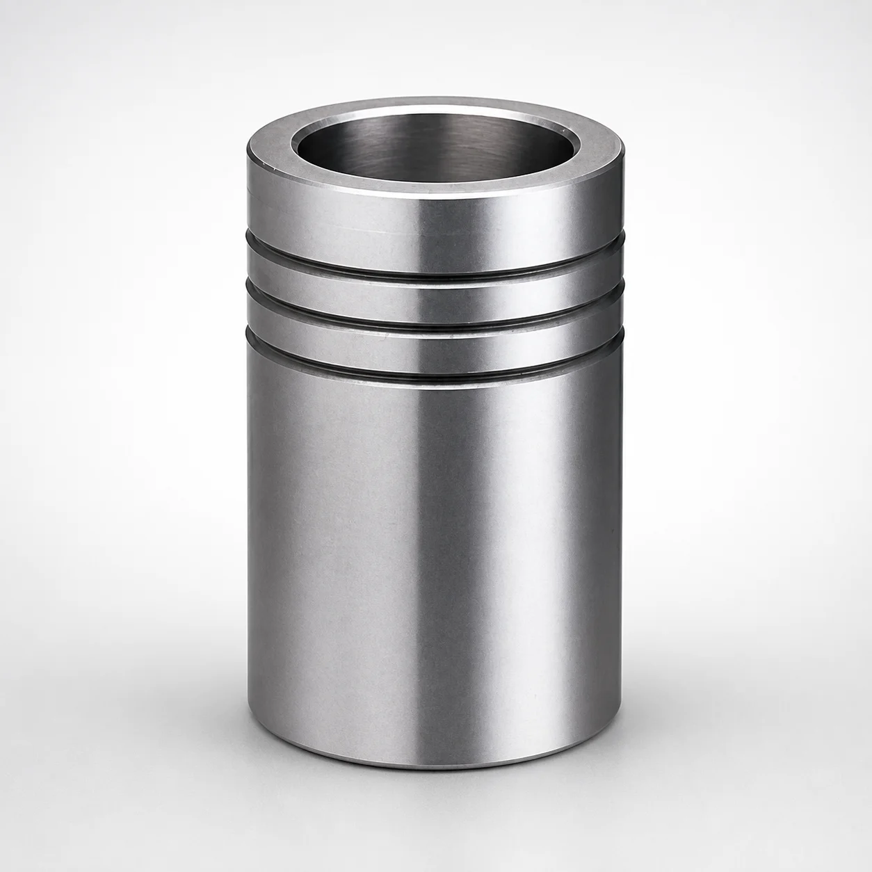
Ball Guide Bushings for Die Sets
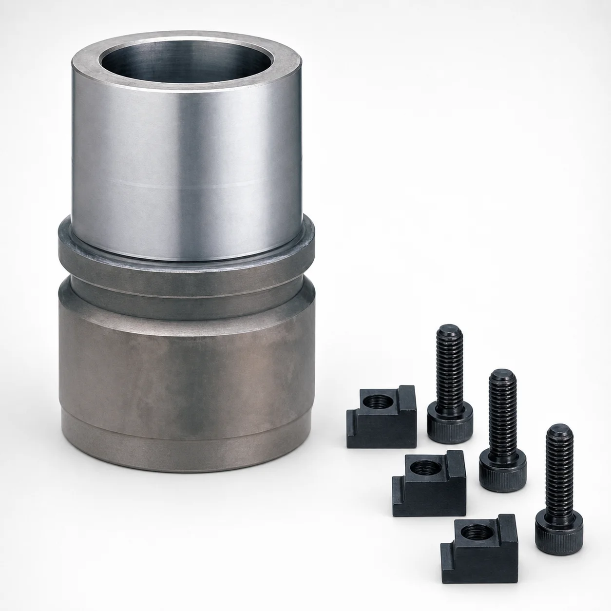
RBB Ball Guide Bushings for Die Sets - Detachable Type
Ball Guide Bushings (LBBS) Loctite Bonded
Aluminum Ball Cages for Guide Bushings with Groove & Circlip
Ball Cages for Guide Bushings - Brass, Groove, with Circlip
Need Custom Specifications?
Our engineering team can help with custom configurations, material selection, and volume pricing.