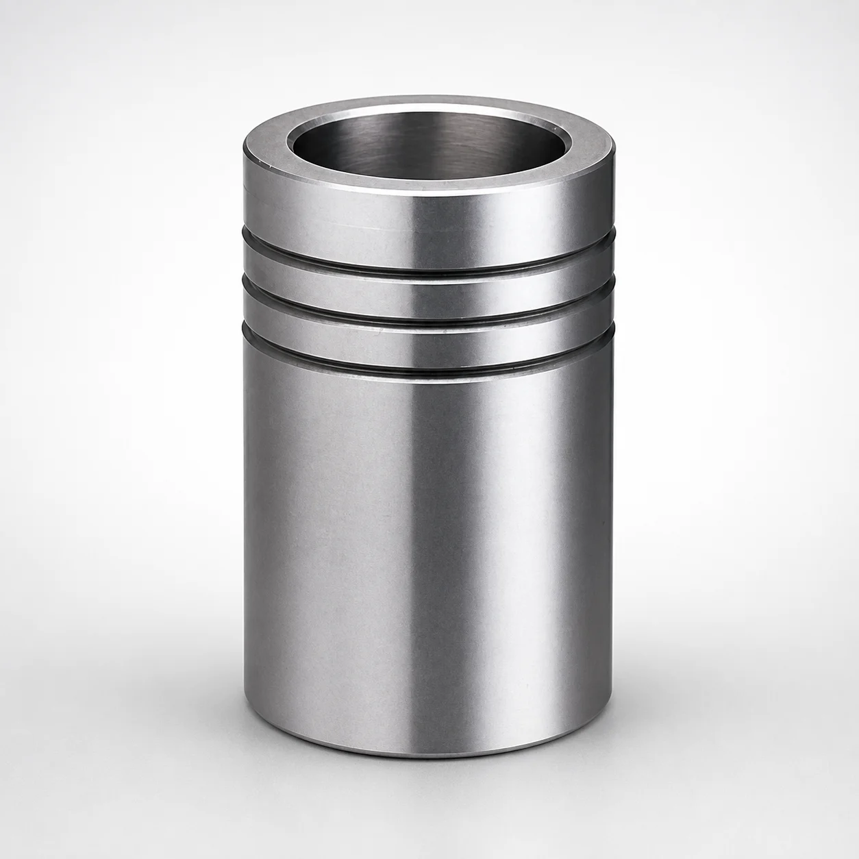
Ball Guide Bushings for Die Sets
Ball guide bushings for die sets are provided as bushing-only components, designed for reliable ball-guided alignment in die sets. The bushing is bonded with Loctite adhesive to help maintain position during production.
- Ball guide bushing type for stable die set guidance and smoother operation
- Loctite adhesive mounting improves retention and assembly consistency
- LBB type construction supports consistent dimensional fit in tooling
- Used in precision die sets where controlled guidance and repeatable assembly matter
Specifications
73 configurations available
| PD (Post diameter) (mm) | Length L (mm) | Alteration LC (L dimension alteration) (mm) | type |
|---|---|---|---|
| 20 | 50 | - | - |
| 20 | - | 25 | - |
| 20 | - | 26 | - |
| 20 | - | 27 | - |
| 20 | - | 28 | - |
| 20 | - | 29 | - |
| 20 | - | 30 | - |
| 20 | - | 31 | - |
| 20 | - | 32 | - |
| 20 | - | 33 | - |
| 20 | - | 34 | - |
| 20 | - | 35 | - |
| 20 | - | 36 | - |
| 20 | - | 37 | - |
| 20 | - | 38 | - |
| 20 | - | 39 | - |
| 20 | - | 40 | - |
| 20 | - | 41 | - |
| 20 | - | 42 | - |
| 20 | - | 43 | - |
| 20 | - | 44 | - |
| 20 | - | 45 | - |
| 20 | - | 46 | - |
| 20 | - | 47 | - |
| 20 | - | 48 | - |
| 20 | - | 49 | - |
| 22 | - | 25 | - |
| 22 | - | 26 | - |
| 22 | - | 27 | - |
| 22 | - | 28 | - |
| 22 | - | 29 | - |
| 22 | - | 30 | - |
| 22 | - | 31 | - |
| 22 | - | 32 | - |
| 22 | - | 33 | - |
| 22 | - | 34 | - |
| 22 | - | 35 | - |
| 22 | - | 36 | - |
| 22 | - | 37 | - |
| 22 | - | 38 | - |
| 22 | - | 39 | - |
| 22 | - | 40 | - |
| 22 | - | 41 | - |
| 22 | - | 42 | - |
| 22 | - | 43 | - |
| 22 | - | 44 | - |
| 22 | - | 45 | - |
| 22 | - | 46 | - |
| 22 | - | 47 | - |
| 22 | - | 48 | - |
Product Guide
Application Scenarios+
Ball guide bushings are used inside large die sets to maintain consistent alignment between moving and fixed tooling during injection, compression, or die-casting cycles. In a typical setup, the bushing-only component is installed in a guide post/bushing interface to provide a stable ball-guided pathway that improves motion repeatability and reduces misalignment wear.
- Automotive and industrial die-casting alignments: Suitable for die sets requiring smooth shut-off and predictable guiding at high cycle rates. The Loctite adhesive bonding helps keep the bushing position stable through repeated thermal cycling.
- Precision forming and stamping tooling: Used where repeatable assembly of subcomponents is critical. The ball guide type supports controlled guidance while the adhesive mounting improves retention during operation.
- Large mold die-set housings and die carriers: The LBB-type construction supports consistent dimensional fit for secure placement when post diameters and bushing lengths must match tooling drawings.
This variant’s adhesive-bonded, ball-guided construction is well-suited when placement accuracy and retention are required after assembly.
Material & Process Details+
The provided specification data identifies this product as a ball guide bushing with Loctite adhesive bonding, but it does not list the steel grade, hardness (HRC), or heat treatment state. Therefore, material properties such as wear resistance and toughness trade-offs cannot be verified from the supplied inputs.
- Material / heat treatment: Not specified in the input data (e.g., nitrided, quenched & tempered, or pre-hardened states are not provided).
- Hardness & wear behavior: No HRC value is included, so performance claims must not be inferred.
- Manufacturing process: The key process detail is adhesive bonding using Loctite to secure placement during die-set assembly.
If your application requires a defined wear/toughness balance, request the corresponding steel grade and heat-treatment/target hardness for this series code before finalizing the die design.
Sizing & Selection Guide+
Correct selection starts by matching the guide interface geometry. Use the post diameter (PD) and the bushing length (L) from your die-set drawing to choose the closest available dimensions. This series supports PD values from 20–60 mm and offers L options of 50, 60, 80, 100, 120 mm.
- Step 1 — PD match: Select the bushing with PD within 20–60 mm that corresponds to the guide post diameter in your die set.
- Step 2 — axial engagement (L): Choose L so the bushing length supports the required guidance overlap and load path for stable alignment.
- Step 3 — LC adjustment: Verify the alteration LC range of 25–59 mm aligns with your planned L dimension alteration between tooling components.
Because this is a bonded placement component, confirm fit strategy with your assembly tolerances. The spec values are the primary constraints; any additional clearance or adhesive gap should be validated against your die-set tolerance stack-up.
Frequently Asked Questions
How do I select the correct ball guide bushing size for my die set using PD and L?+
Choose the bushing PD to match the guide post diameter. This series covers PD = 20–60 mm and provides fixed bushing lengths L = 50, 60, 80, 100, 120 mm.
Then confirm the selected L supports the required axial guidance engagement in your tooling design.
What does the LC (L dimension alteration) specification mean for tooling compatibility?+
The input provides an LC range of 25–59 mm, indicating allowable variation related to L dimension alteration between mating components.
When integrating this bushing into a die-set assembly, verify your planned L alteration falls within that range to avoid misalignment or insufficient engagement.
Is the bushing supplied as a complete ball-guided component, or does it require additional parts?+
This product is described as a bushing-only component designed for ball-guided alignment in die sets.
It is intended to be mounted in the tooling interface and secured by the included Loctite adhesive bonding approach.
What is the purpose of Loctite adhesive bonding on this ball guide bushing?+
The description states that the bushing is bonded with Loctite adhesive to help maintain placement during production.
In die-set applications, this improves retention and assembly consistency so the bushing stays properly located as the tooling cycles.
Do I need to verify the steel grade and hardness before selecting this bushing?+
The supplied specification data does not include a steel grade, heat-treatment condition, or target hardness (HRC).
For applications where wear resistance and toughness are critical, request the corresponding material/heat-treatment details for series code 110100159770 before finalizing the design.
Related Products
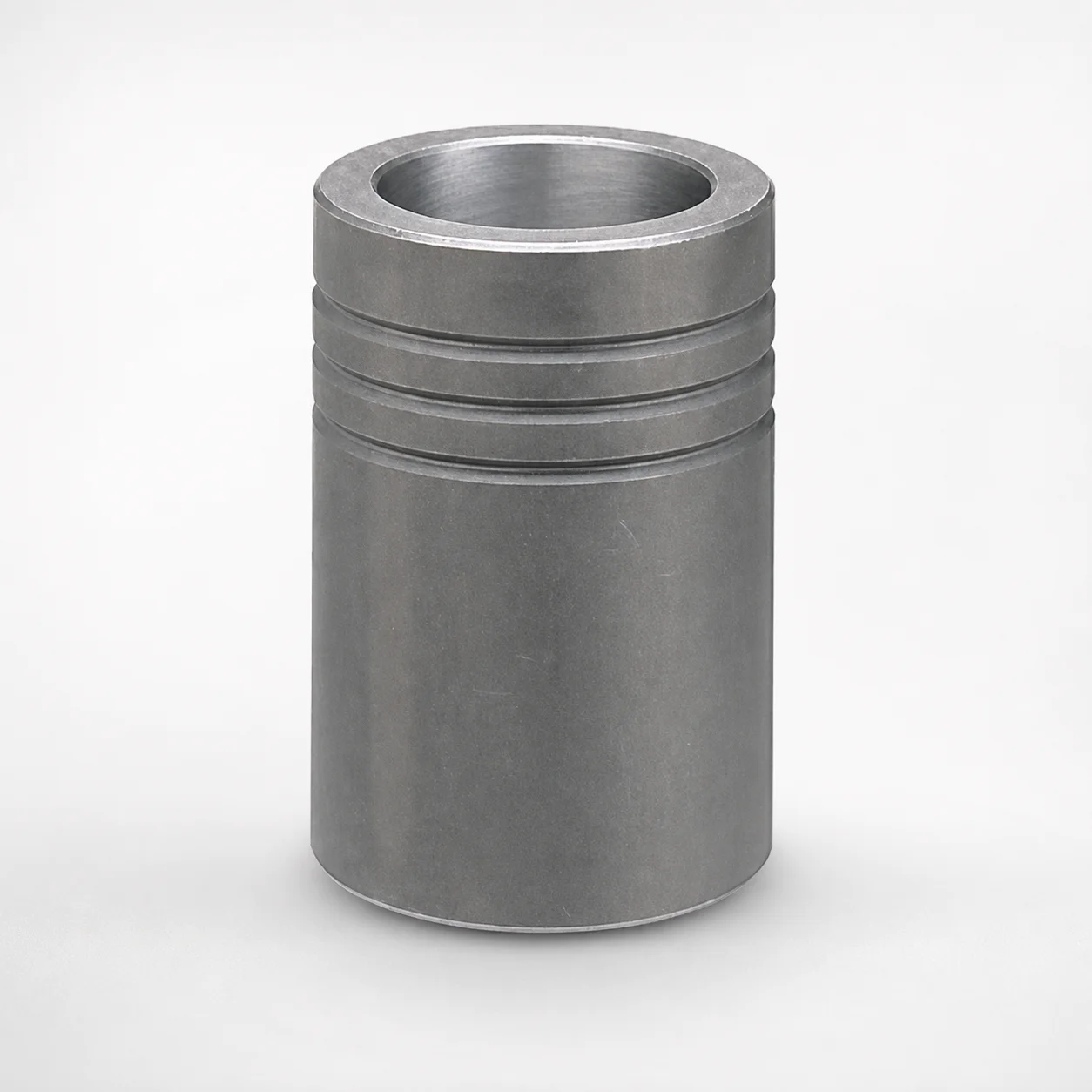
MBB Ball Guide Bushings for Die Sets Bonded by Devcon Adhesive
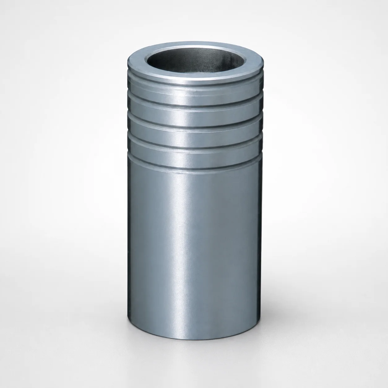
Ball Guide Bushings for Die Sets - Loctite Adhesive LBB Type
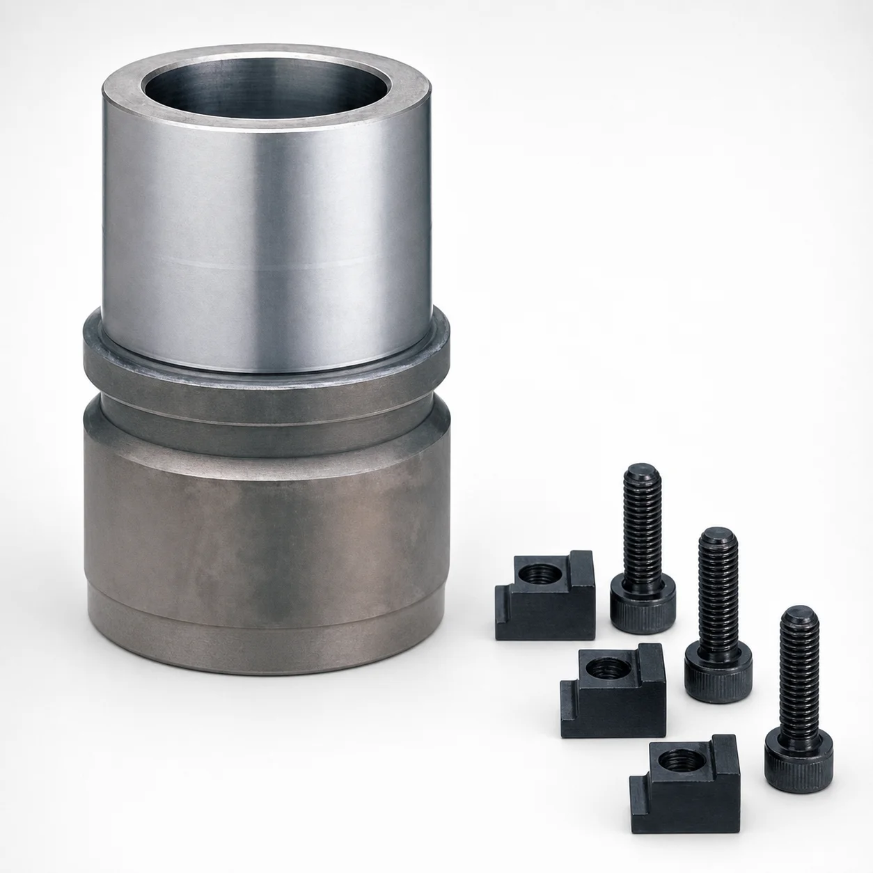
RBB Ball Guide Bushings for Die Sets - Detachable Type
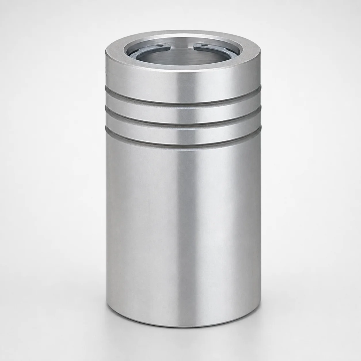
Ball Guide Bushings (LBBS) Loctite Bonded
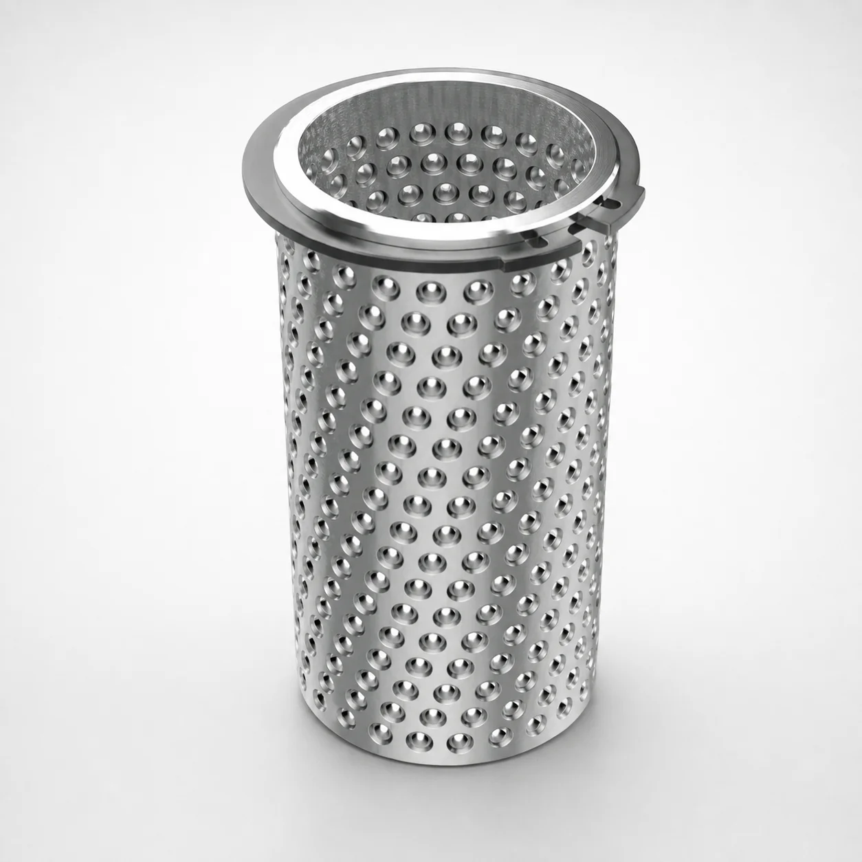
Aluminum Ball Cages for Guide Bushings with Groove & Circlip
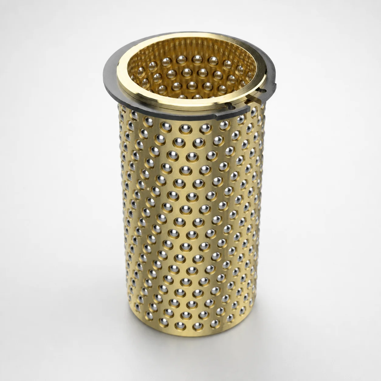
Ball Cages for Guide Bushings - Brass, Groove, with Circlip
Need Custom Specifications?
Our engineering team can help with custom configurations, material selection, and volume pricing.