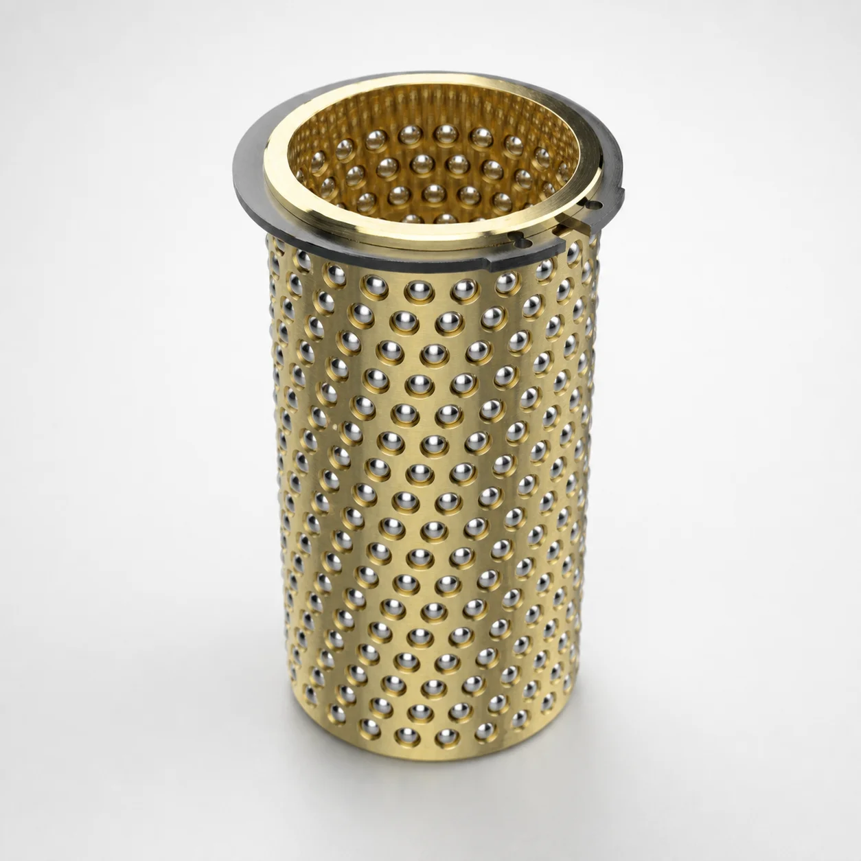
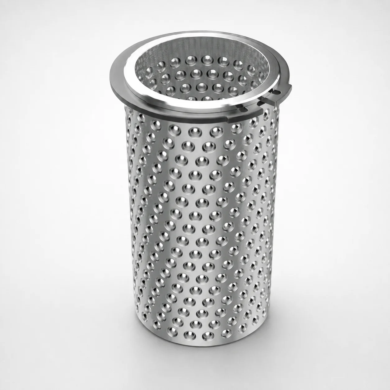
Ball Cages for Guide Bushings - Brass, Groove, with Circlip
Ball Cages for Guide Bushings (Brass/Steel) with a groove and circlip retain rolling elements to support consistent guide performance in die set mechanisms. Designed to match DGBI3S, DGBI5S, and DGBI7S guide bushing systems for smooth, controlled motion.
- Groove cage geometry with integrated circlip for positive ball retention during operation
- Material options of Brass and Steel balance wear resistance and dimensional stability
- Supports a wide range of cage lengths L and ball counts to fit different guide layouts
- Used in precision die set guide bushings requiring repeatable alignment and reliable ball guidance
Specifications
133 configurations available
| Length L (mm) | D (Diameter) (mm) | Number of Balls |
|---|---|---|
| 40 | 12 | 176 |
| 56 | 12 | 272 |
| 45 | 15 | 144 |
| 56 | 15 | 192 |
| 63 | 15 | 224 |
| 71 | 15 | 256 |
| 24 | 16 | 64 |
| 28 | 16 | 80 |
| 45 | 16 | 144 |
| 56 | 16 | 192 |
| 63 | 16 | 224 |
| 71 | 16 | 256 |
| 31 | 19 | 120 |
| 45 | 19 | 180 |
| 56 | 19 | 240 |
| 71 | 19 | 320 |
| 80 | 19 | 360 |
| 95 | 19 | 440 |
| 24 | 20 | 80 |
| 28 | 20 | 80 |
| 31 | 20 | 120 |
| 45 | 20 | 180 |
| 56 | 20 | 240 |
| 71 | 20 | 320 |
| 80 | 20 | 360 |
| 95 | 20 | 440 |
| 31 | 24 | 120 |
| 40 | 24 | 160 |
| 45 | 24 | 180 |
| 56 | 24 | 240 |
| 71 | 24 | 320 |
| 80 | 24 | 360 |
| 95 | 24 | 440 |
| 120 | 24 | 560 |
| 40 | 25 | 160 |
| 45 | 25 | 180 |
| 56 | 25 | 240 |
| 71 | 25 | 320 |
| 80 | 25 | 360 |
| 95 | 25 | 440 |
| 120 | 25 | 560 |
| 40 | 30 | 120 |
| 45 | 30 | 140 |
| 50 | 30 | 160 |
| 56 | 30 | 180 |
| 71 | 30 | 240 |
| 80 | 30 | 280 |
| 95 | 30 | 340 |
| 105 | 30 | 380 |
| 120 | 30 | 440 |
Product Guide
Application Scenarios+
These ball cages are used inside guide bushing assemblies for large injection and die-casting tooling where smooth, repeatable sliding motion is required. In die set mechanisms such as automotive connector and bracket molds, the cage’s groove geometry and integrated circlip help maintain stable ball circulation, supporting consistent alignment during repeated open/close cycles.
- Large die-casting tooling: Pair with DGBI3S/DGBI5S/DGBI7S guide bushing systems to preserve controlled motion under frequent load reversals.
- High-cycle production molds: Brass/steel cage construction helps retain dimensional stability while supporting reliable ball guidance over long runs.
- Long stroke guide layouts: The available cage length L = 24–240 mm allows matching different guide spans without compromising retention.
This variant is suited because it is specifically intended for the DGBI3S, DGBI5S, and DGBI7S ball-guide architecture, with circlip retention to reduce ball migration risk.
Material & Process Details+
This series is offered as a brass cage and a steel cage (brass/steel cage family), targeting balanced performance between wear resistance and dimensional stability in guide bushing service. Brass is typically selected when smoother sliding and stable dimensions are prioritized in systems where balls circulate under controlled loads.
- Brass cage: Good bearing behavior for ball guidance; favors stable operation where surface finish and running smoothness are critical.
- Steel cage: Higher structural robustness for applications requiring greater mechanical stiffness and long-term dimensional retention under heavier duty cycles.
Heat treatment and hardness values are not provided in the supplied data; therefore, selection should be based on whether your die set load profile and wear expectations favor the brass vs. steel cage variant. For hardness and wear-critical designs, request the specific material/process documentation for the chosen cage option before final qualification.
Sizing & Selection Guide+
To select the correct cage, start by matching the diameter D and overall length L to your guide bushing system geometry. This series covers D = 12–80 mm and L = 24–240 mm, so choose the variant that fits the guide bushing’s internal cage envelope and stroke requirements.
- Match D: Select the cage diameter within 12–80 mm so the cage groove profile aligns with the ball path in your DGBI3S, DGBI5S, or DGBI7S assembly.
- Match L: Use the required 24–240 mm cage length to span the active guide region and maintain correct ball spacing along the guide.
- Verify ball count: Confirm the available Number of Balls = 64–1472 matches the designed ball layout for your guide bushing to avoid under/over-loading of the race.
Tolerances are not specified in the provided data; consult your bushing design drawing for fit requirements. If multiple sizes are candidates, prioritize the exact D and L dimensions that align with the guide bushing cavity/core and the calculated ball count.
Frequently Asked Questions
Which guide bushing types are these ball cages compatible with?+
These ball cages are specified for the DGBI3S, DGBI5S, and DGBI7S guide bushing systems. When designing a die set guide mechanism, ensure the cage’s groove and retention style match that architecture.
How do I choose the correct cage diameter and length for my guide bushing?+
Select D within 12–80 mm and L within 24–240 mm. The cage’s diameter must align with the ball path in the DGBI series bushing, while the length should cover the active guide region required for controlled motion.
What ball count range is available, and how does it affect design load distribution?+
The series covers Number of Balls = 64–1472. Match the ball count to your guide bushing’s designed ball layout so the load is distributed as intended across the circulating rolling elements.
Should I select a brass cage or a steel cage for wear-critical die set operation?+
Both brass and steel variants are available in this series, targeting different duty profiles. Use brass when smoother running behavior and stable operation are prioritized, and consider steel when added structural stiffness and robustness are needed.
Does the integrated circlip influence ball retention during mold open/close cycles?+
Yes. The cage design includes an integrated circlip to support positive ball retention during operation. For high-cycle molds, this helps reduce the risk of ball migration that could disturb alignment and guidance.
Related Products
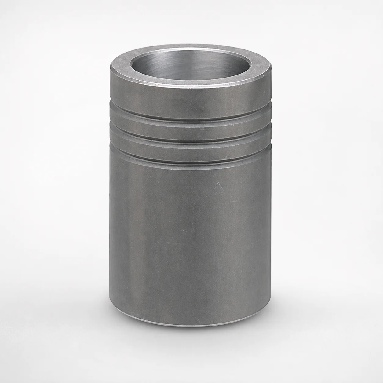
MBB Ball Guide Bushings for Die Sets Bonded by Devcon Adhesive
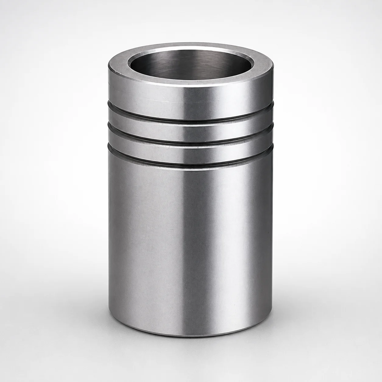
Ball Guide Bushings for Die Sets
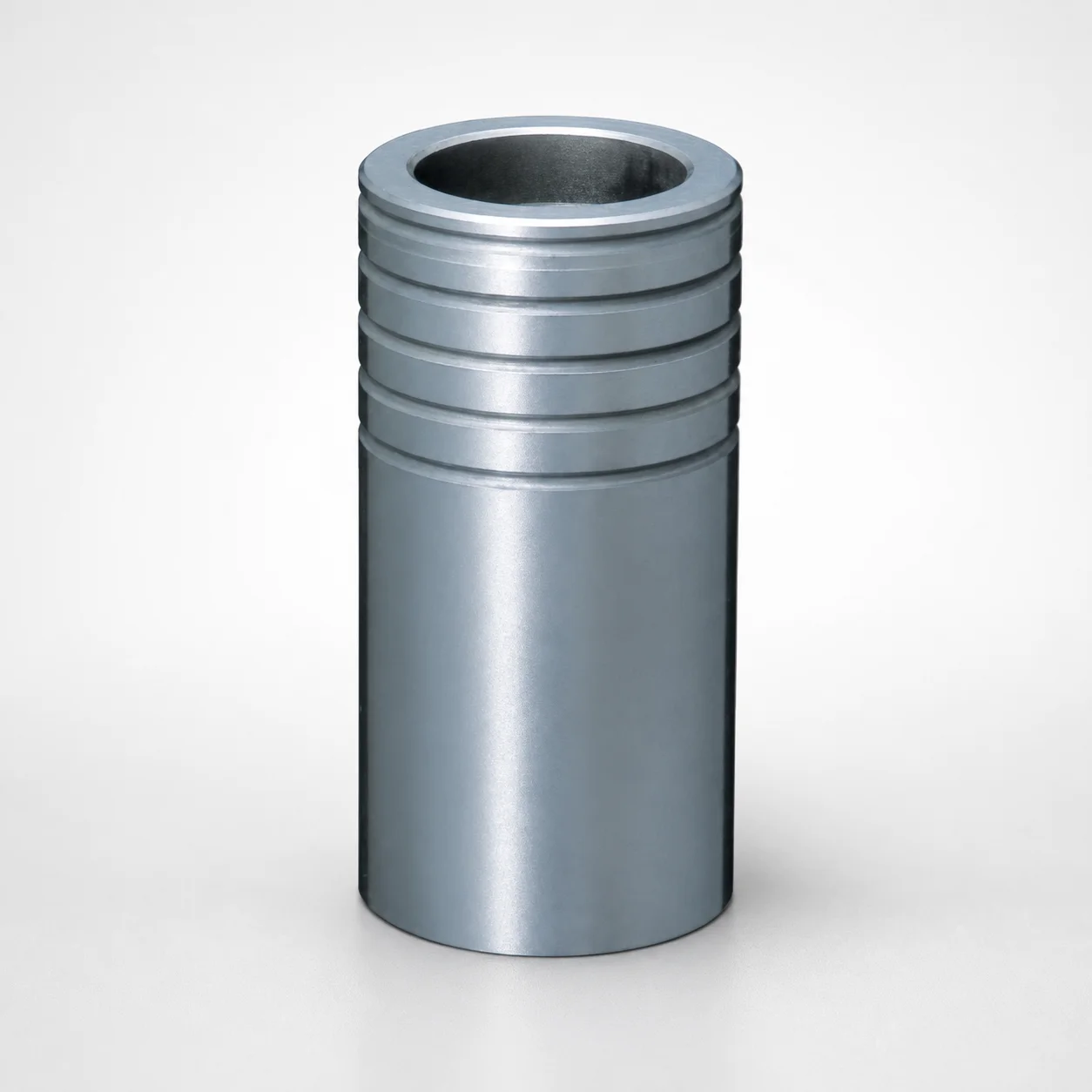
Ball Guide Bushings for Die Sets - Loctite Adhesive LBB Type
RBB Ball Guide Bushings for Die Sets - Detachable Type
Ball Guide Bushings (LBBS) Loctite Bonded
Aluminum Ball Cages for Guide Bushings with Groove & Circlip
Need Custom Specifications?
Our engineering team can help with custom configurations, material selection, and volume pricing.