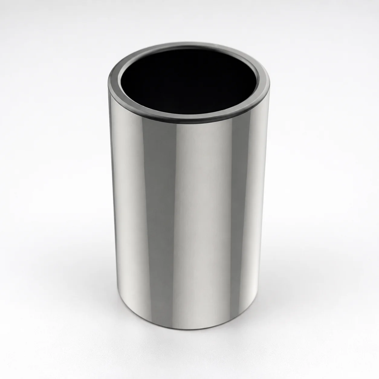
ISO 9448-3 1.1730 Steel Guide Bushings for Ball Cages
Guide Bushings for Ball Cages (1.1730 steel) are manufactured to ISO 9448-3 and heat-treated to 61–63 HRC for stable support of ball cages. Anaerobic adhesive type helps achieve consistent bonding during die set assembly.
- Built to ISO 9448-3 for repeatable compatibility with guide assemblies
- Heat-treated 1.1730 steel at 61–63 HRC for wear-resistant performance
- Anaerobic adhesive type supports secure positioning and assembly integrity
- Designed for ball cage guidance in precision die set mechanisms
Specifications
85 configurations available
| Length L (mm) | D (Pillar outer diameter) (mm) | Preferred Ball Cage Length l (mm) |
|---|---|---|
| 23 | 15 | 45 |
| 30 | 15 | - |
| 37 | 15 | - |
| 47 | 15 | - |
| 60 | 15 | - |
| 23 | 16 | 45 |
| 30 | 16 | - |
| 37 | 16 | - |
| 47 | 16 | - |
| 60 | 16 | - |
| 23 | 19 | 45 |
| 30 | 19 | 45 |
| 37 | 19 | 45 |
| 47 | 19 | 56 |
| 60 | 19 | 71 |
| 77 | 19 | 95 |
| 23 | 20 | 45 |
| 30 | 20 | 45 |
| 37 | 20 | 45 |
| 47 | 20 | 56 |
| 60 | 20 | 71 |
| 77 | 20 | 95 |
| 23 | 24 | 45 |
| 30 | 24 | 45 |
| 37 | 24 | 45 |
| 47 | 24 | 56 |
| 60 | 24 | 71 |
| 77 | 24 | 95 |
| 23 | 25 | 45 |
| 30 | 25 | 45 |
| 37 | 25 | 45 |
| 47 | 25 | 56 |
| 60 | 25 | 71 |
| 77 | 25 | 95 |
| 30 | 30 | 45 |
| 37 | 30 | 50 |
| 47 | 30 | 56 |
| 60 | 30 | 71 |
| 77 | 30 | 95 |
| 95 | 30 | 120 |
| 30 | 32 | 45 |
| 37 | 32 | 50 |
| 47 | 32 | 56 |
| 60 | 32 | 71 |
| 77 | 32 | 95 |
| 95 | 32 | 120 |
| 30 | 38 | 45 |
| 37 | 38 | 50 |
| 47 | 38 | 63 |
| 60 | 38 | 80 |
Product Guide
Application Scenarios+
Guide bushing elements like these are used in injection and die-casting mold tooling where a ball cage must be precisely guided during die set motion.
- For precision die sets, they support ball cages that slide within the guide path, helping maintain alignment under repeated opening/closing.
- In large mold mechanisms (e.g., die-casting accessory assemblies), the stable 61–63 HRC heat treatment supports wear-resistant guidance even with frequent contact between cage and guide surfaces.
- When assembly repeatability is critical, the anaerobic adhesive type is suited to secure positioning during die assembly, reducing micro-shifts that can degrade cage alignment over time.
The ISO 9448-3 conformance and hardened 1.1730 steel variant are particularly suitable when engineers need consistent fit with standardized guide assemblies and predictable wear performance for long-cycle mold operation.
Material & Process Details+
This guide bushing is made from 1.1730 steel and manufactured to ISO 9448-3. The part is heat-treated to 61–63 HRC, providing a balance of wear resistance and toughness for sliding contact with ball cage components.
- Hardness (61–63 HRC): improves abrasion and surface durability in guide applications.
- Wear vs. toughness trade-off: higher hardness increases resistance to scuffing but requires sound mounting practices to avoid stress concentrations.
- Adhesive compatibility: the specified anaerobic adhesive type supports stable assembly bonding to maintain guidance geometry.
If alternative steels are considered for other duty cycles, hardness targets should remain comparable; lower hardness generally reduces wear life, while significantly higher hardness can increase sensitivity to impact or misalignment.
Sizing & Selection Guide+
Select the guide bushing to match your mold’s ball-cage guidance geometry and the required insertion footprint.
- Choose the pillar outer diameter D within 15–80 mm to fit the guide bore or corresponding seat in the die set.
- Select length L from 23–120 mm based on how much axial support your ball cage needs for stable alignment across the stroke.
- Confirm the preferred ball cage length l matches the application within 45–140 mm, so the bushing provides full guidance coverage where the cage travels.
Because the bushing is produced to ISO 9448-3, use the standard to ensure compatibility with your guide assembly stack-up. Verify fit at assembly interfaces (bushing seat and cage mating surfaces) and maintain proper installation alignment to preserve performance at 61–63 HRC.
Frequently Asked Questions
How do I select the correct guide bushing diameter (D) and length (L) for a ball cage guidance application?+
Use D (pillar outer diameter) in the range 15–80 mm to match the die set guide bore or seat. Then choose L (length) between 23–120 mm so the bushing provides sufficient axial support along the cage travel. Finally, verify the application’s preferred ball cage length l is within 45–140 mm for consistent guidance coverage.
What hardness does this ISO 9448-3 guide bushing reach, and why does it matter for wear during mold cycles?+
This variant is heat-treated to 61–63 HRC. That hardness level improves resistance to abrasion and scuffing where the guide surface supports sliding ball cage motion. The higher hardness-to-wear benefit should still be balanced with careful alignment to avoid stressing the hardened components.
Is the adhesive type compatible with die set assembly, and what does “anaerobic” imply for positioning?+
The specification indicates an anaerobic adhesive type for secure assembly bonding. In practical terms, it helps maintain the bushing’s relative position during die assembly, reducing the risk of micro-shift that can affect ball cage alignment. Use installation alignment procedures to ensure the bonded joint supports the hardened bushing geometry.
What does ISO 9448-3 compliance guarantee for compatibility with standardized guide assemblies?+
The part is manufactured to ISO 9448-3, which is intended to standardize dimensional compatibility for guide bushing applications. For engineers, this reduces uncertainty when integrating with existing standardized guide components and mechanisms in die sets. When selecting dimensions, stay within the listed ranges for D, L, and the intended ball cage length l.
When choosing between different steel grades for guide bushings, how should I compare hardness targets to 1.1730 at 61–63 HRC?+
This bushing uses 1.1730 steel and is heat-treated to 61–63 HRC. If you compare alternative steels, align your selection to similar hardness targets to maintain wear resistance under sliding contact. Be mindful that lower hardness can shorten wear life, while significantly higher hardness may reduce toughness margins if misalignment or shock loads occur.
Related Products
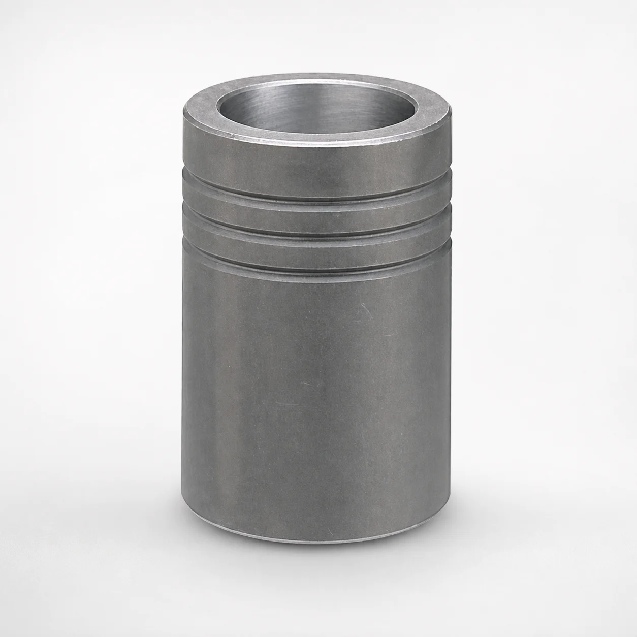
MBB Ball Guide Bushings for Die Sets Bonded by Devcon Adhesive
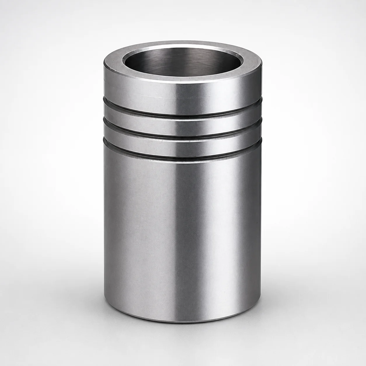
Ball Guide Bushings for Die Sets
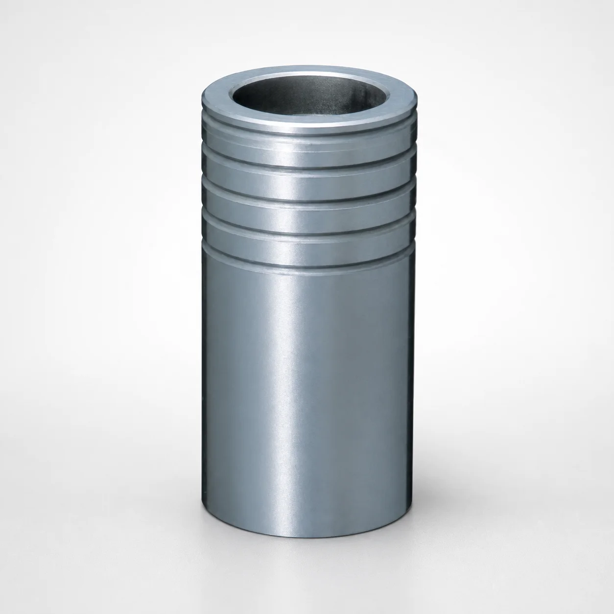
Ball Guide Bushings for Die Sets - Loctite Adhesive LBB Type
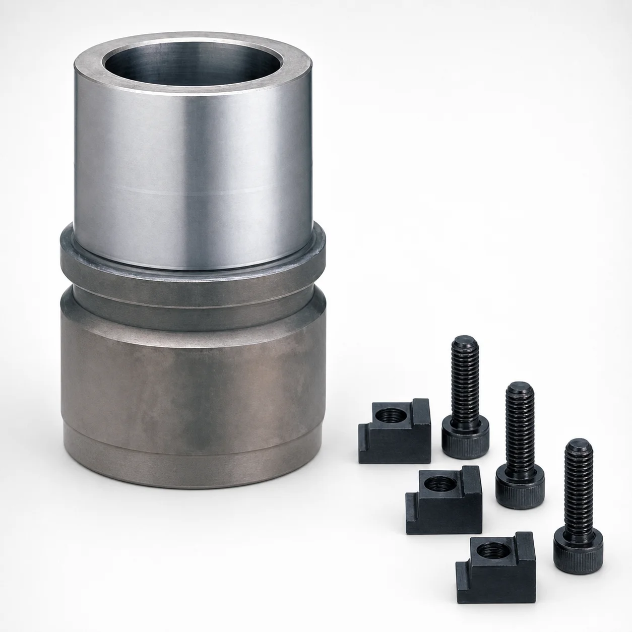
RBB Ball Guide Bushings for Die Sets - Detachable Type
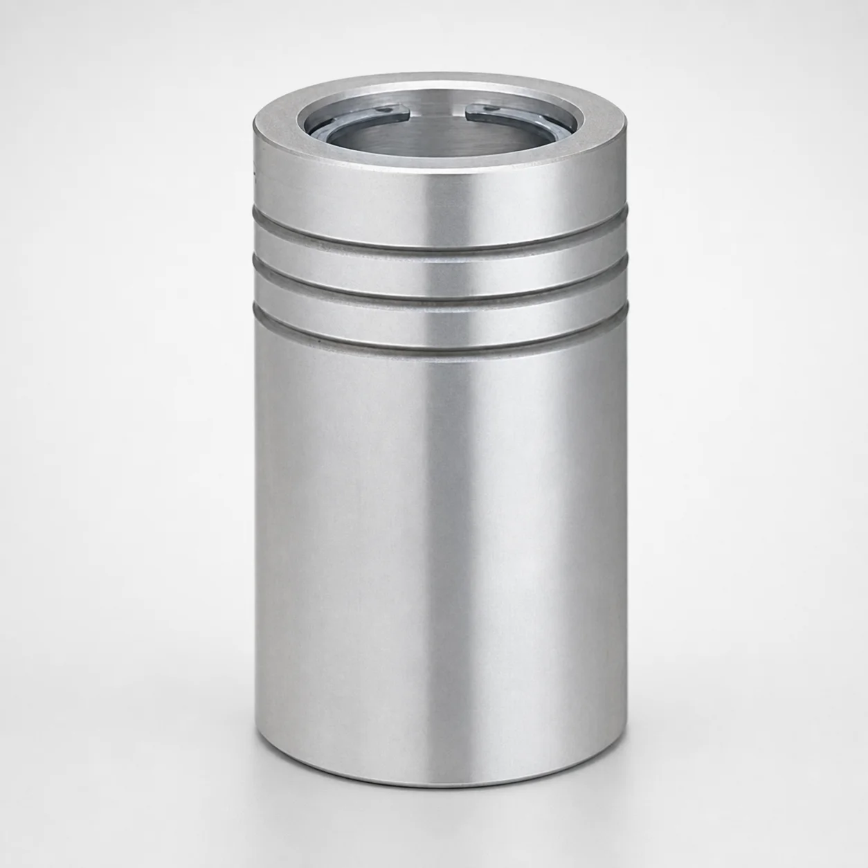
Ball Guide Bushings (LBBS) Loctite Bonded
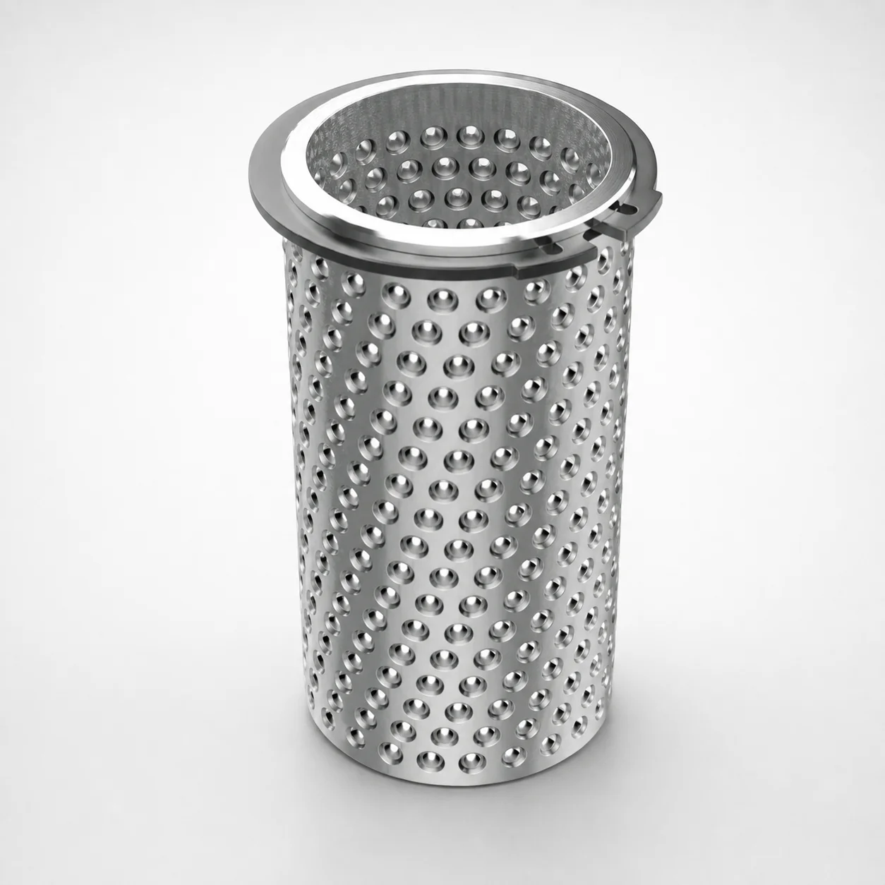
Aluminum Ball Cages for Guide Bushings with Groove & Circlip
Need Custom Specifications?
Our engineering team can help with custom configurations, material selection, and volume pricing.