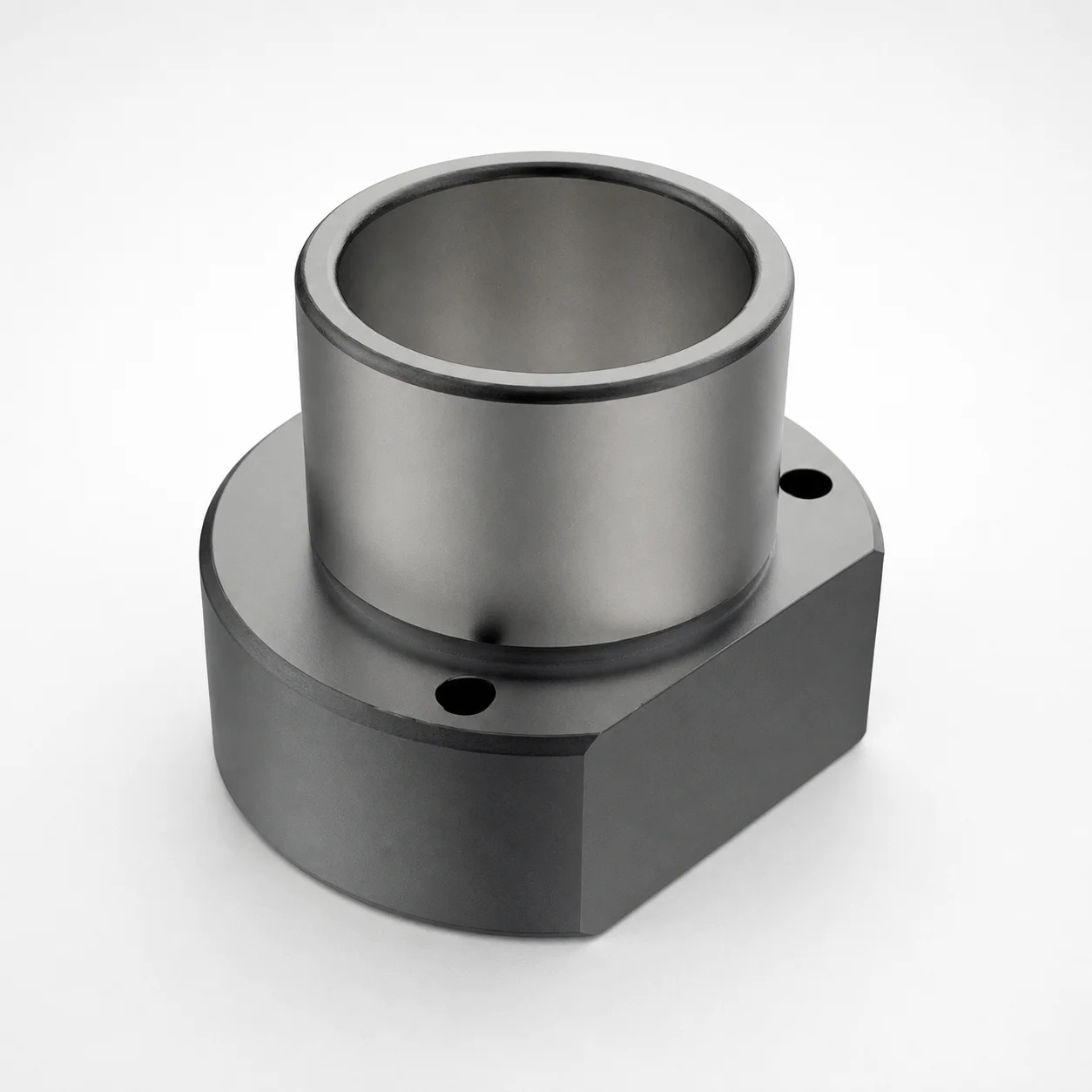
ISO 9448-5 Steel Guide Bushings for Ball Cages - Flange Flat-Sided
Guide bushings for ball cages (1.7131 steel) are designed for stable alignment in ball cage assemblies, featuring a flange flat-sided profile that improves handling, seating, and positioning. Built for reliable guide performance under production load.
- One-side flange flat-sided geometry supports consistent cage alignment and mounting
- 1.7131 steel provides robust core strength for guide bushing applications
- 61~63 HRC hardening supports wear-resistant performance in continuous use
- ISO 9448-5 configuration supports compatibility with standard die and ball cage systems
Specifications
35 configurations available
| Length L (mm) | D (Pillar outer diameter) (mm) |
|---|---|
| 38 | 19 |
| 45 | 19 |
| 52 | 19 |
| 38 | 20 |
| 45 | 20 |
| 52 | 20 |
| 38 | 24 |
| 55 | 24 |
| 62 | 24 |
| 38 | 25 |
| 55 | 25 |
| 62 | 25 |
| 45 | 30 |
| 62 | 30 |
| 72 | 30 |
| 45 | 32 |
| 62 | 32 |
| 72 | 32 |
| 55 | 38 |
| 67 | 38 |
| 77 | 38 |
| 55 | 40 |
| 67 | 40 |
| 77 | 40 |
| 62 | 48 |
| 89 | 48 |
| 102 | 48 |
| 62 | 50 |
| 89 | 50 |
| 102 | 50 |
| 89 | 60 |
| 102 | 60 |
| 89 | 63 |
| 102 | 63 |
| 125 | 80 |
Product Guide
Application Scenarios+
Where it fits in the tool: This flange flat-sides guide bushing is used inside injection mold die sets that incorporate ball cage mechanisms, where the cage must remain precisely aligned during opening/closing and under cyclic loading.
- Automotive connector and housing molds: In high-cycle tooling, the one-side flange with flat-sided geometry helps consistent seating and prevents rotational misalignment of the ball cage guide area.
- Large die-casting and heavy-part molds: For the large-mold-die-casting category, the bushing’s wear-resistant hardness supports stable guide performance when sliding friction and contamination are present.
- Precision actuation molds: When maintaining repeatable motion is critical, the ISO 9448-5 configuration supports compatibility with standard die/ball cage layouts while using this variant’s flattened flange profile for easier handling and positioning.
Why this variant: The flat-sides flange improves mounting repeatability and alignment stability, while the specified hardened steel range supports long service life in abrasive, production conditions.
Material & Process Details+
Steel grade & meaning: The bushing is made from 1.7131 steel (as specified for this ISO 9448-5 guide bushing variant). With a target hardness of 61~63 HRC, it is designed to balance wear resistance for sliding guide contact with sufficient toughness for guide operation in production environments.
Heat treatment state: The stated hardness implies a hardened condition suitable for guide bushings (i.e., heat treated to the 61~63 HRC range rather than supplied in a soft condition).
- Wear resistance: Higher hardness (61~63 HRC) improves resistance to abrasive wear at the guide interface.
- Toughness trade-off: At this hardness level, components typically require controlled design and installation to avoid chipping under edge loading or misalignment.
- Compatibility: The ISO 9448-5 configuration is intended to fit standard ball cage tooling systems, allowing material performance to translate directly into guide life.
Sizing & Selection Guide+
Key dimensions to match: Select the guide bushing by D (pillar outer diameter) and L (length). Available ranges for this series are D = 19 ~ 80 mm and L = 38 ~ 125 mm.
- Match D to the cage/pillar interface: Choose the bushing with the same pillar outer diameter target so the guide seats correctly within the ball cage assembly without excessive clearance.
- Match L to the guide engagement depth: Use L to ensure sufficient guiding length for stable alignment while fitting within the die space of the large-mold-die-casting tool.
- Flange flat-sides orientation: Confirm that the one-side flattened flange profile is oriented for correct seating and anti-rotation behavior in your assembly.
Tolerance & fit considerations: Since only the dimensional ranges are provided here, verify your drawing tolerances for the mating pillar and cage bores. If your ball cage system is sensitive to play, prioritize minimizing clearance by selecting the tightest compatible D and ensuring proper seating of the flange flat-sides feature.
Frequently Asked Questions
How do I choose the correct D (pillar outer diameter) for ISO 9448-5 ball cage guide bushings?+
What L (length) range should I consider for stable guide engagement in large die-casting tools?+
Why is the one-side flange with flat-sided geometry important for ball cage alignment?+
What hardness level does this bushing provide, and how does it affect wear resistance?+
Is this guide bushing compatible with standard ISO 9448-5 ball cage die layouts?+
Related Products
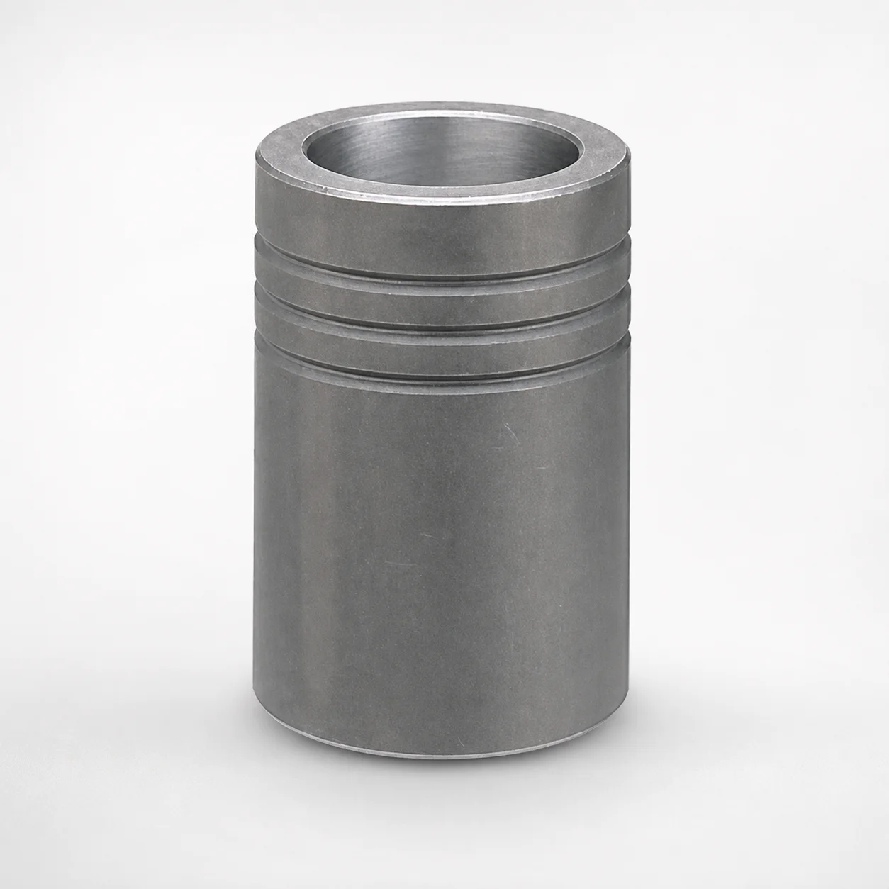
MBB Ball Guide Bushings for Die Sets Bonded by Devcon Adhesive
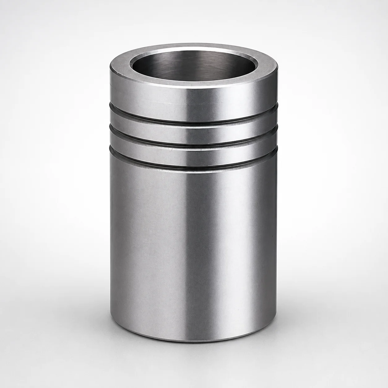
Ball Guide Bushings for Die Sets
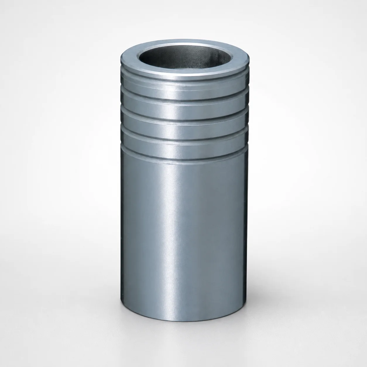
Ball Guide Bushings for Die Sets - Loctite Adhesive LBB Type
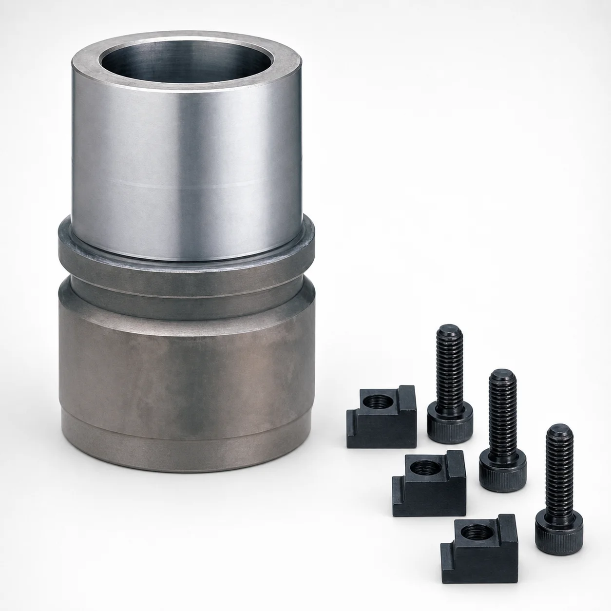
RBB Ball Guide Bushings for Die Sets - Detachable Type
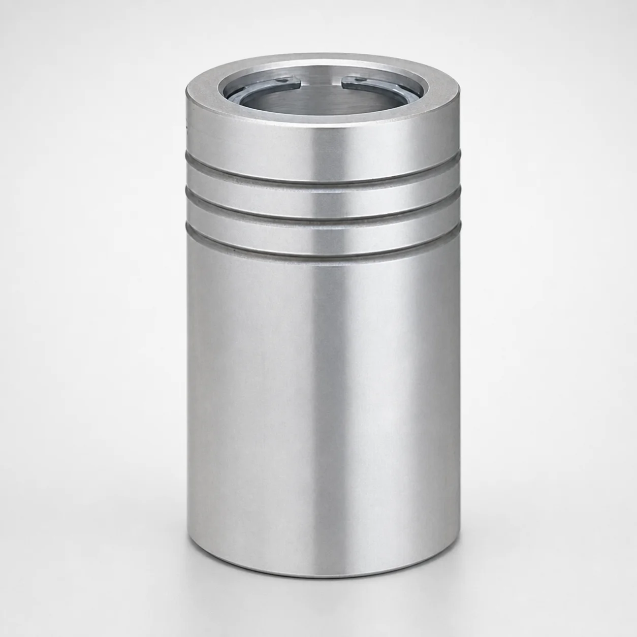
Ball Guide Bushings (LBBS) Loctite Bonded
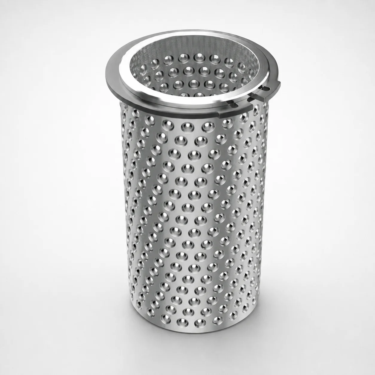
Aluminum Ball Cages for Guide Bushings with Groove & Circlip
Need Custom Specifications?
Our engineering team can help with custom configurations, material selection, and volume pricing.