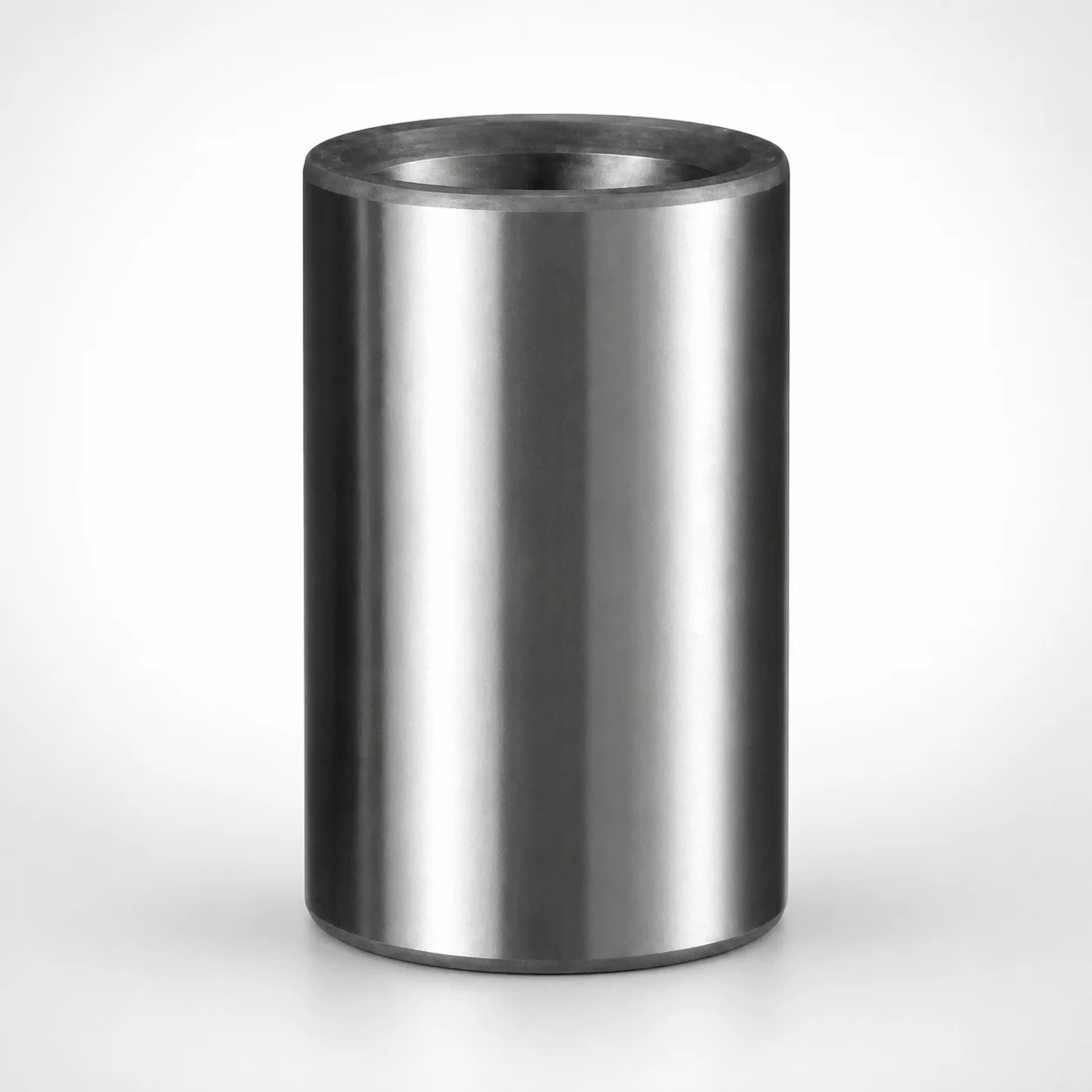
Ball Guide Sleeve Bushings - Press Fit Type - Inch
Ball Guide Sleeve Bushings (Steel) are designed for press-fit installation in inch-based die sets, delivering stable linear guidance and reliable component alignment. As bushings only, they simplify maintenance and replacements while keeping guided motion consistent under cycling loads.
- Ball guide design supports smooth, repeatable motion during press operation
- Steel construction resists wear for long service intervals in tooling
- Tight inch tolerance range (0.0005 in) helps maintain precise fit-up
- Inch press-fit style for guide hardware compatibility in die set assemblies
Specifications
138 configurations available
| Nom. Pin Diameter (in) | Dimension L1 (in) |
|---|---|
| 3/4 | 1.625 |
| 3/4 | 1.875 |
| 3/4 | 2.125 |
| 3/4 | 2.375 |
| 3/4 | 2.625 |
| 3/4 | 2.875 |
| 3/4 | 3.125 |
| 3/4 | 3.375 |
| 3/4 | 3.625 |
| 3/4 | 3.875 |
| 3/4 | 4.375 |
| 3/4 | 5.875 |
| 1 | 1.875 |
| 1 | 2.125 |
| 1 | 2.375 |
| 1 | 2.625 |
| 1 | 2.875 |
| 1 | 3.125 |
| 1 | 3.375 |
| 1 | 3.625 |
| 1 | 3.875 |
| 1 | 4.125 |
| 1 | 4.375 |
| 1 | 4.625 |
| 1 | 4.875 |
| 1 | 5.375 |
| 1 | 5.875 |
| 1 | 6.375 |
| 1 | 6.875 |
| 1 1/4 | 2.375 |
| 1 1/4 | 2.625 |
| 1 1/4 | 2.875 |
| 1 1/4 | 3.125 |
| 1 1/4 | 3.375 |
| 1 1/4 | 3.625 |
| 1 1/4 | 3.875 |
| 1 1/4 | 4.125 |
| 1 1/4 | 4.375 |
| 1 1/4 | 4.625 |
| 1 1/4 | 4.875 |
| 1 1/4 | 5.375 |
| 1 1/4 | 5.875 |
| 1 1/4 | 6.375 |
| 1 1/4 | 6.875 |
| 1 1/4 | 7.875 |
| 1 1/4 | 8.875 |
| 1 1/2 | 2.875 |
| 1 1/2 | 3.125 |
| 1 1/2 | 3.375 |
| 1 1/2 | 3.625 |
Product Guide
Application Scenarios+
In injection molding and die-casting tooling, press-fit guide sleeve bushings are used to control linear motion of mating guide components during opening/closing cycles and under die-set loads. This inch-based variant is suited to large-mold and die-casting assemblies where consistent alignment reduces wear and helps stabilize parting-line behavior.
- Die-set guide systems: Install as a sleeve bushing in inch-compatible guide hardware to support smooth, repeatable motion; the press-fit style helps maintain position with minimal adjustment.
- Precision die sets for tough cycling: Steel construction supports wear resistance in guided interfaces where frequent press operation can otherwise degrade guidance accuracy over time.
- Maintenance and component replacement: Because this is a bushing-only element, it simplifies refurbishment so guided motion remains consistent after wear inspection.
Material & Process Details+
This product is built from steel, selected for durability in guided motion interfaces. In press-fit guide applications, the key goal is maintaining stable dimensional integrity while resisting surface wear from repeated sliding/rolling contacts in the guide path.
- Heat treatment state: The provided data does not specify a particular hardness or heat treatment (e.g., quenched & tempered, nitrided). Please confirm the heat-treatment spec from your quote request for exact performance targets.
- Hardness & wear vs. toughness trade-off: Typical hardened guide steels balance higher wear resistance (often via quench/temper or surface hardening) with controlled toughness to avoid chipping under load. The final balance depends on the documented hardness and heat treatment.
- Material comparison: No alternate material grades are listed in the input; selection is therefore limited to the steel construction indicated.
For design validation, request the hardness (HRC) and treatment details to match your cycling loads and allowable guide wear.
Sizing & Selection Guide+
Use the provided dimensions to match the sleeve bushing to your guide pin and die-set layout. Start by selecting the Nom. Pin Diameter (in) in the range 1 ~ 3 (inches) so the bushing correctly fits the mating guide pin size used in your inch-based tooling.
- Choose the correct length L1: Select Dimension L1 (in) within 1.625 ~ 13.875 to match the required guide support length in the cavity/core structure.
- Match to cavity/core requirements: Verify that the installed bushing length provides the intended bearing/support zone without interfering with adjacent components or ejector/actuation hardware.
- Fit and tolerance considerations: The description indicates a tight inch tolerance range of 0.0005 in; ensure your guide-pin and mating bore specs in the die set are consistent with this tolerance to achieve stable alignment after press-fit installation.
- Configurable vs. fixed: Pin diameter and L1 are variable within the given ranges; other dimensions are not provided in the input and should be confirmed for your part number.
Frequently Asked Questions
How do I select the correct Nom. Pin Diameter when using this press-fit ball guide sleeve bushing in an inch die set?+
What L1 length should I use to ensure proper guide support in a large-mold die-casting assembly?+
What tolerance should I expect for press-fit alignment performance?+
Is the sleeve bushing meant to be maintenance-replaced without reworking the entire guide system?+
What steel hardness or heat treatment is used, and how does it affect wear and toughness?+
Related Products
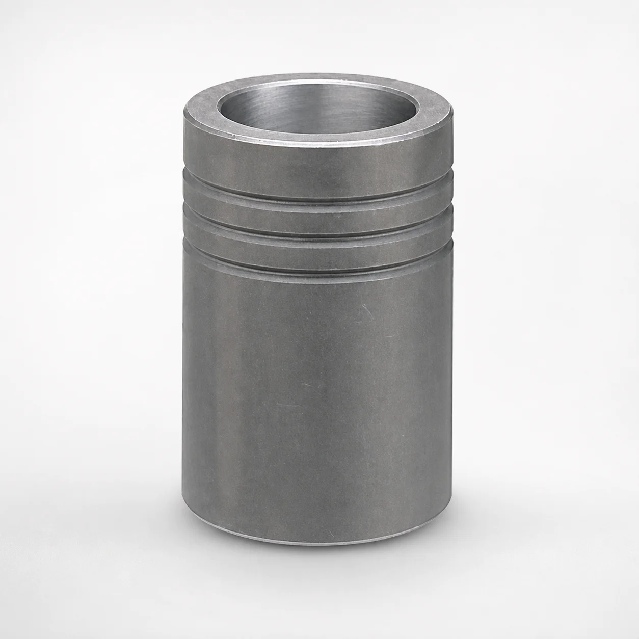
MBB Ball Guide Bushings for Die Sets Bonded by Devcon Adhesive
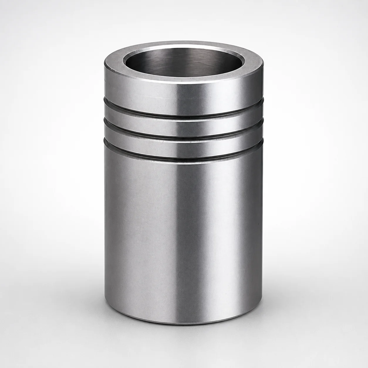
Ball Guide Bushings for Die Sets
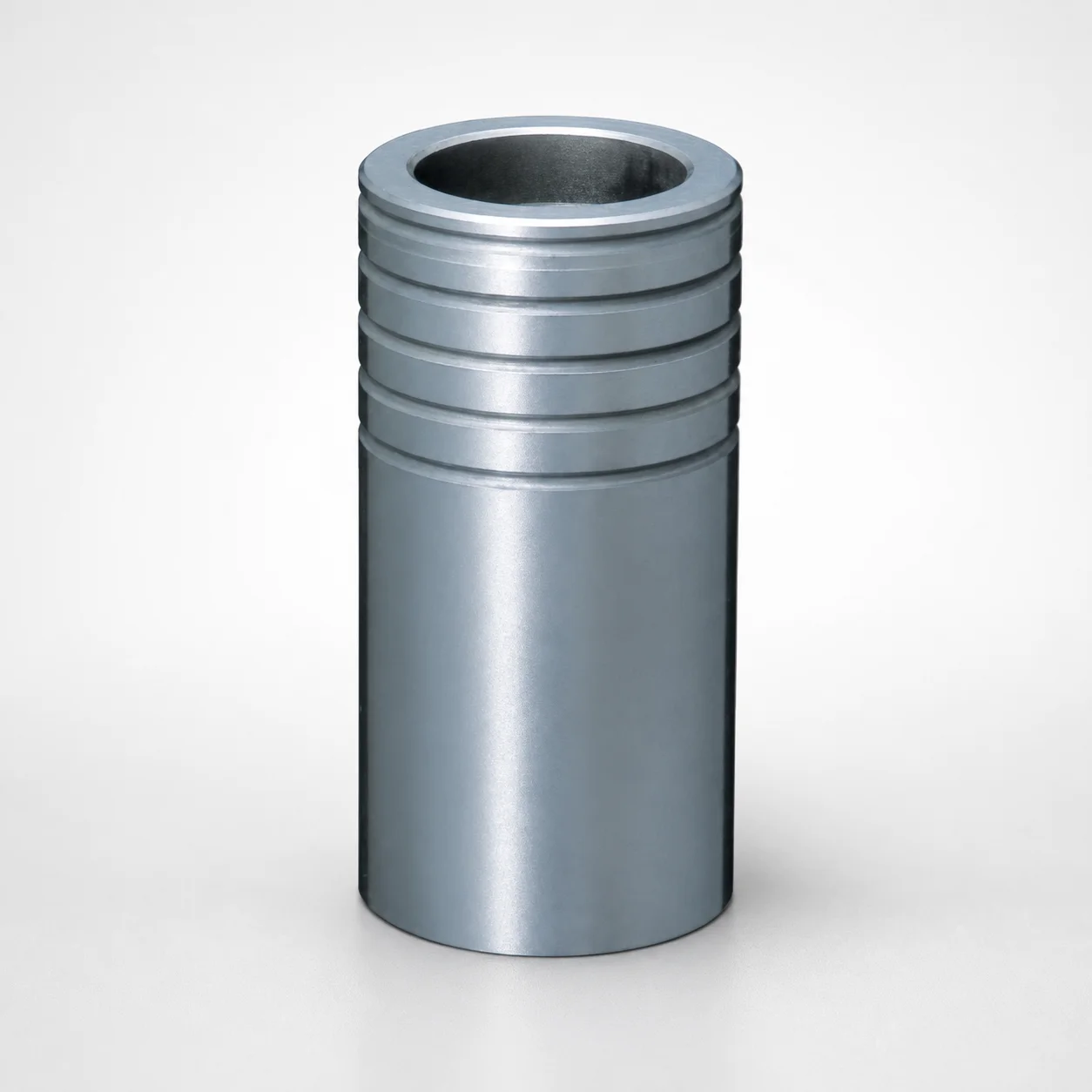
Ball Guide Bushings for Die Sets - Loctite Adhesive LBB Type
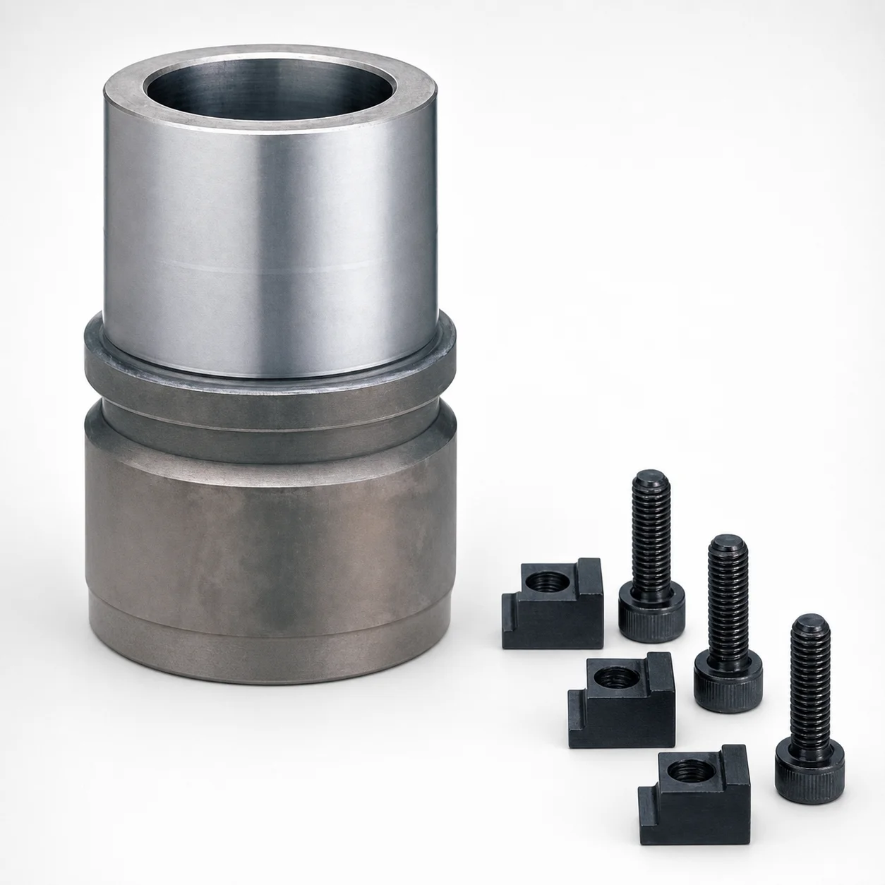
RBB Ball Guide Bushings for Die Sets - Detachable Type
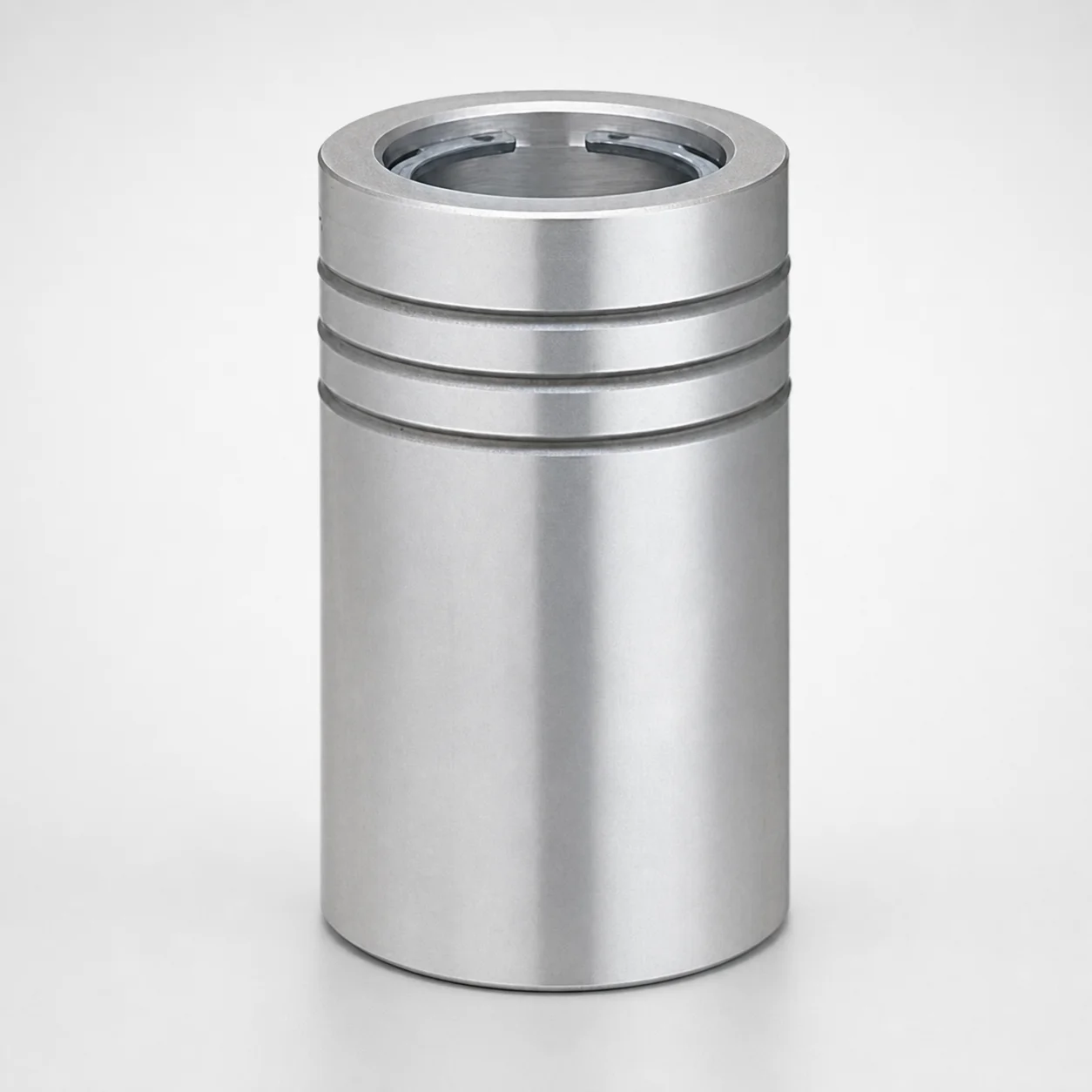
Ball Guide Bushings (LBBS) Loctite Bonded
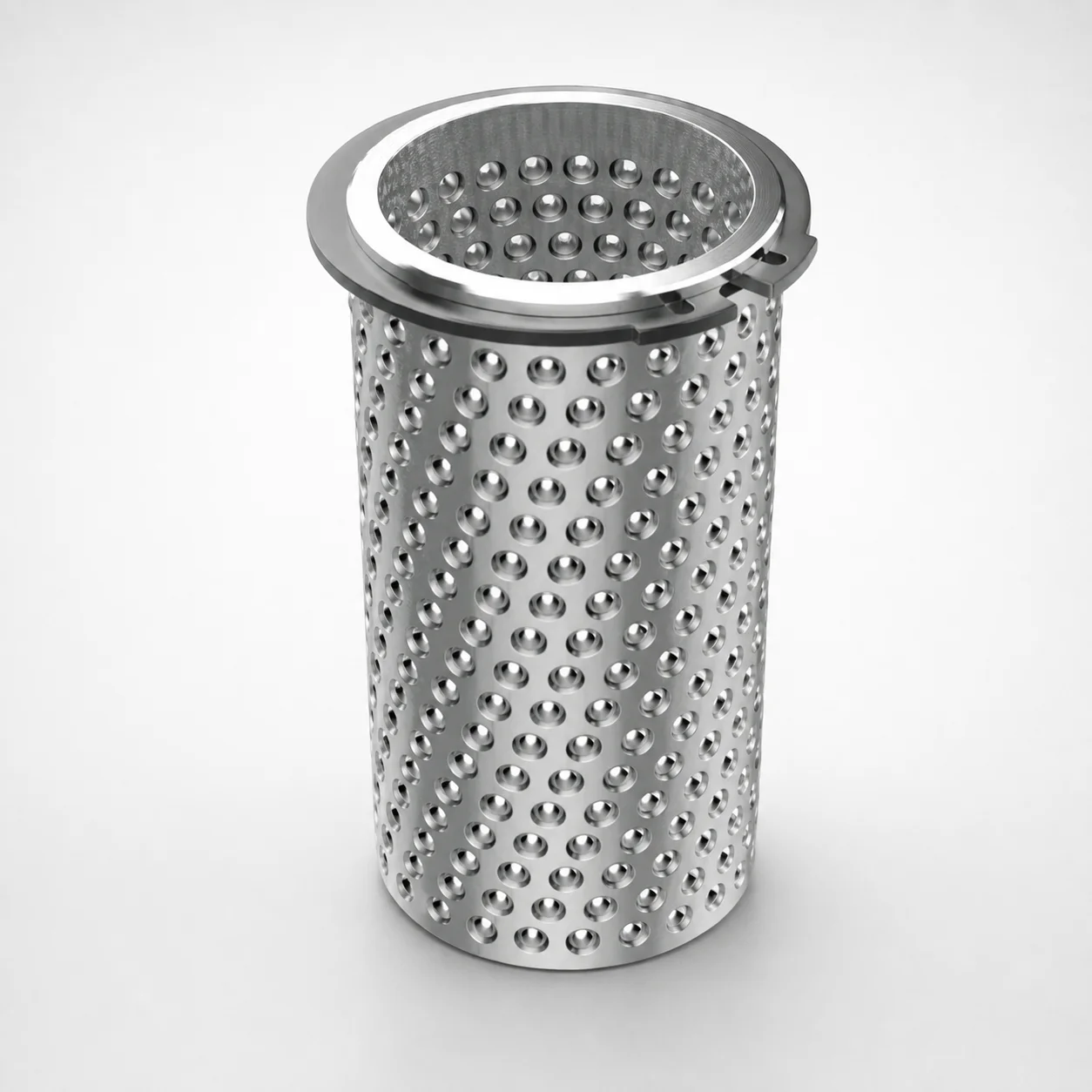
Aluminum Ball Cages for Guide Bushings with Groove & Circlip
Need Custom Specifications?
Our engineering team can help with custom configurations, material selection, and volume pricing.