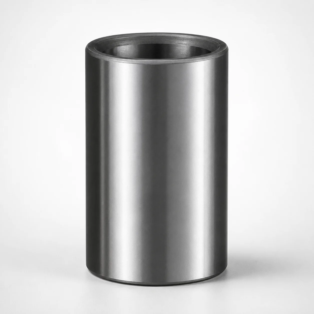
Ball Guide Bushings Metric (Steel)
Ball guide bushings (Steel) for metric applications deliver steady alignment and smooth guided movement in die sets. Designed as bushing-only components, they help maintain consistent motion during forming and press cycles.
- Ball guide bushing type for stable, low-friction guidance
- Steel construction provides durable wear resistance in tooling
- Supports metric die set integration for efficient assembly
- Commonly used with die set guided systems requiring precise fit
Specifications
71 configurations available
| Nom. Pin Diameter (mm) | Dimension L1 (mm) |
|---|---|
| 32 | 75 |
| 32 | 80 |
| 32 | 90 |
| 32 | 95 |
| 32 | 100 |
| 32 | 105 |
| 32 | 115 |
| 32 | 125 |
| 32 | 140 |
| 32 | 150 |
| 32 | 165 |
| 32 | 175 |
| 32 | 220 |
| 32 | 230 |
| 40 | 100 |
| 40 | 105 |
| 40 | 115 |
| 40 | 120 |
| 40 | 125 |
| 40 | 135 |
| 40 | 140 |
| 40 | 150 |
| 40 | 165 |
| 40 | 175 |
| 40 | 190 |
| 40 | 200 |
| 40 | 215 |
| 40 | 230 |
| 40 | 250 |
| 40 | 280 |
| 40 | 300 |
| 50 | 125 |
| 50 | 135 |
| 50 | 140 |
| 50 | 150 |
| 50 | 165 |
| 50 | 175 |
| 50 | 190 |
| 50 | 200 |
| 50 | 215 |
| 50 | 230 |
| 50 | 250 |
| 50 | 280 |
| 50 | 300 |
| 50 | 330 |
| 50 | 350 |
| 63 | 150 |
| 63 | 165 |
| 63 | 175 |
| 63 | 190 |
Product Guide
Application Scenarios+
Ball guide bushings (steel) are used inside metric die sets to maintain stable alignment and smooth, guided motion during repeated press or forming cycles. Because they act as bushing-only components, they integrate into the guided system to support consistent movement without forcing changes to the rest of the die build.
- Automotive/industrial die-casting tooling: for large, high-cycle die sets that require reliable guided motion to keep the parting line alignment stable as loads fluctuate.
- Progressive or forming press stations: to reduce misalignment during stroke-to-stroke operation, supporting smooth movement where low-friction guidance helps maintain repeatability.
- General metalworking fixtures: in guided mechanisms where metric die set integration is required for efficient assembly and consistent fit.
This steel variant is suited for tooling environments where durable wear resistance and long service life are needed under sliding contact.
Material & Process Details+
This bushing is made from steel, selected for durable wear resistance in guided die-set applications. In tooling use, steel bushings typically balance hardness and toughness so the component can resist abrasion while still tolerating the shocks and load variations common in press cycles.
- Wear resistance: improved by adopting an appropriate heat treatment for the steel grade used by the manufacturer.
- Toughness trade-off: higher hardness generally increases wear resistance but can reduce impact toughness if over-hardened; proper tempering maintains toughness.
- Heat treatment state: typically supplied in a heat-treated condition suitable for sliding guidance (exact grade and hardness are not specified in the provided data).
When comparing steel options, the main engineering decision is whether the selected heat treatment targets higher abrasion resistance or greater resistance to chipping under intermittent load.
Sizing & Selection Guide+
Use the provided nominal pin diameter and axial length to match the bushing to your guided system requirements. Select the Nom. Pin Diameter (mm) from the available sizes: 32, 40, 50, 63, 80. Then choose the required Dimension L1 (mm) within 75 ~ 500.
- Match to the die guided components: the bushing’s nominal pin diameter must correspond to the diameter of the mating guide pin used in your metric die set.
- Set effective guidance length: dimension L1 should provide the contact/support length needed to maintain alignment across the stroke.
- Fit and tolerance considerations: confirm clearance/interference assumptions with your guide pin and housing design. For sliding guidance, ensure the overall assembly tolerances allow smooth motion without excessive play.
Dimensions listed above are the selectable sizes for this series; configure L1 to your die stack-up and stroke alignment needs.
Frequently Asked Questions
Which nominal pin diameters are available for this metric ball guide bushing?+
What is the available range for the bushing length (L1) when designing a die guided system?+
Is this a full guide rail component or a bushing-only element inside the die set?+
What material performance should I expect from the steel construction?+
How do I select the correct bushing size to minimize misalignment during press operation?+
Related Products
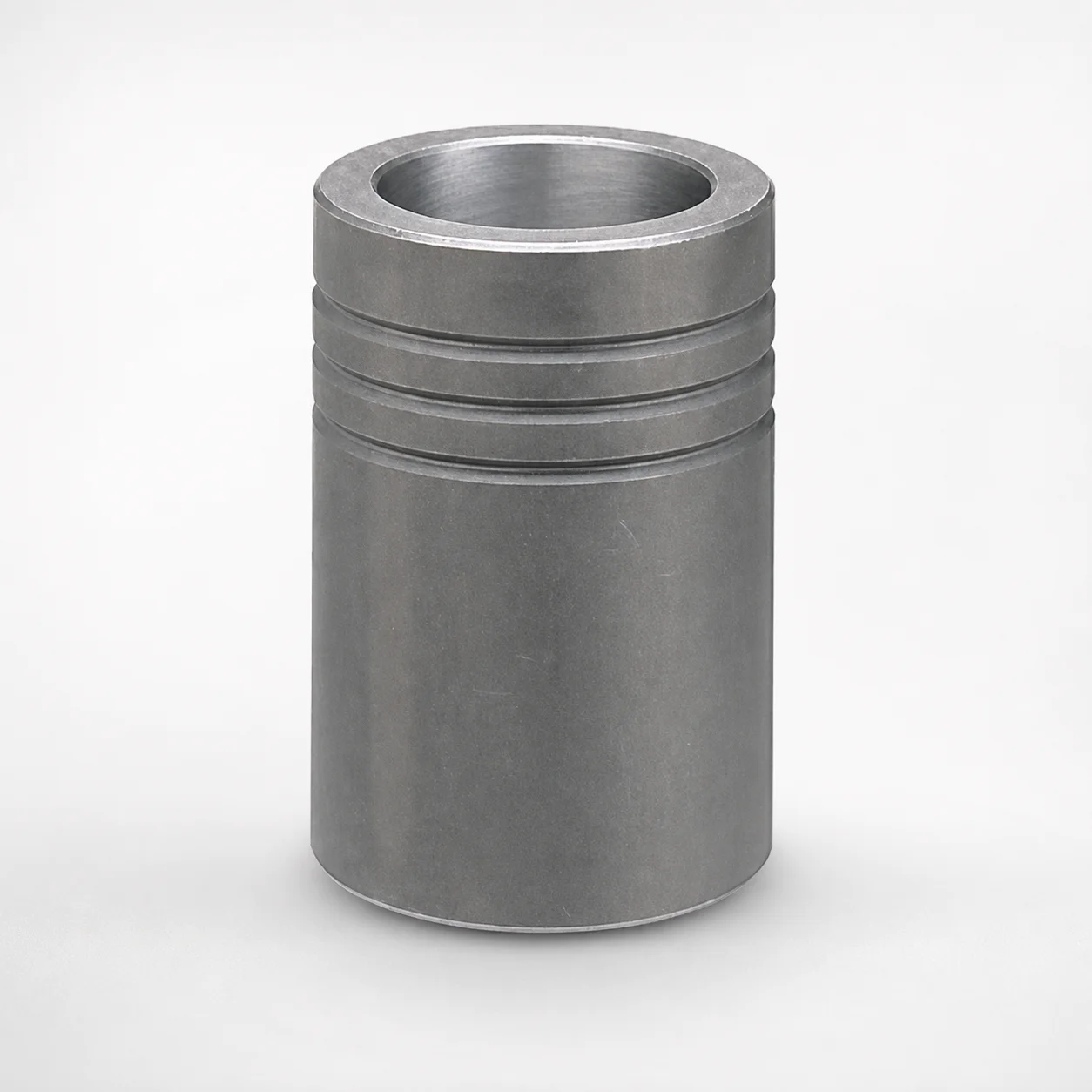
MBB Ball Guide Bushings for Die Sets Bonded by Devcon Adhesive
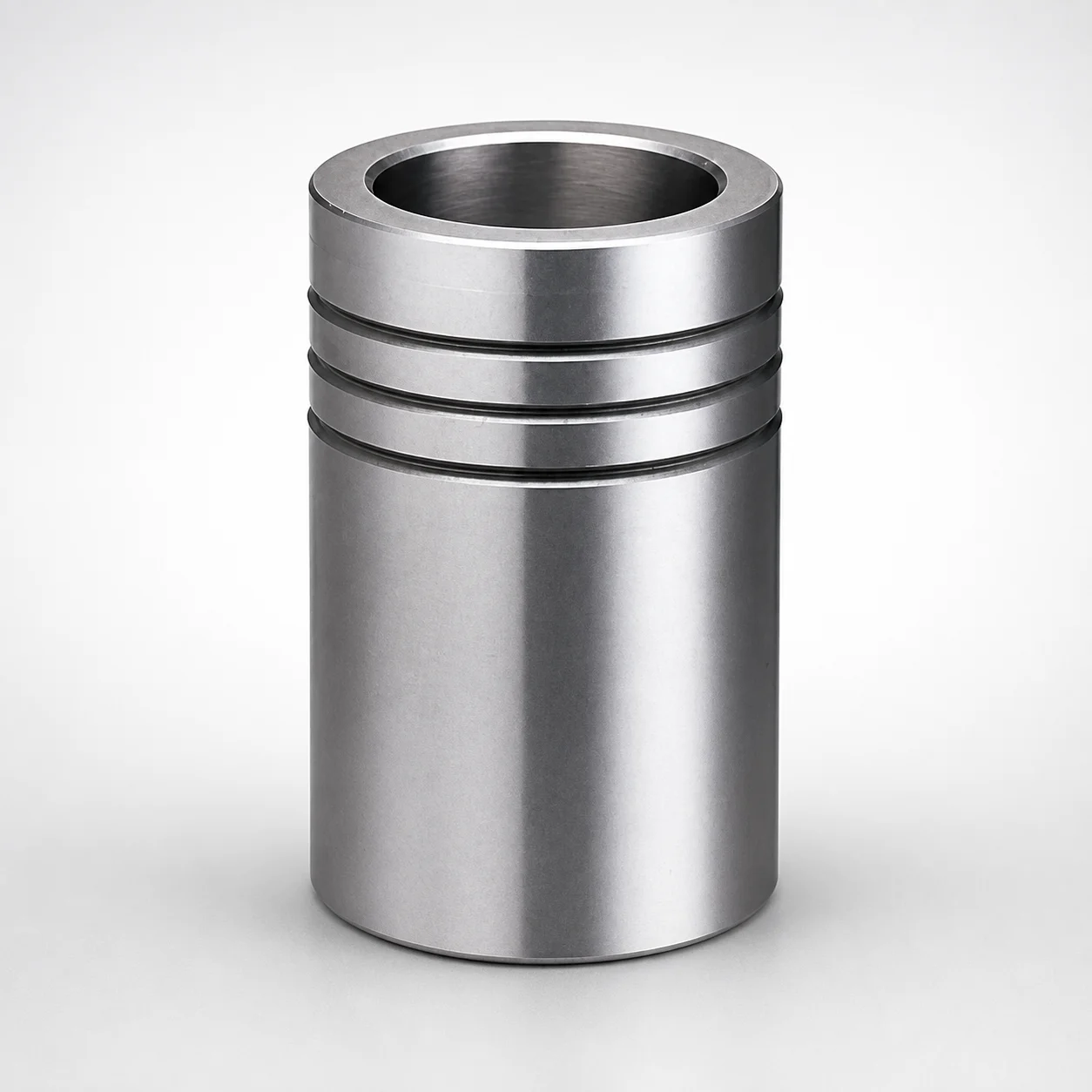
Ball Guide Bushings for Die Sets
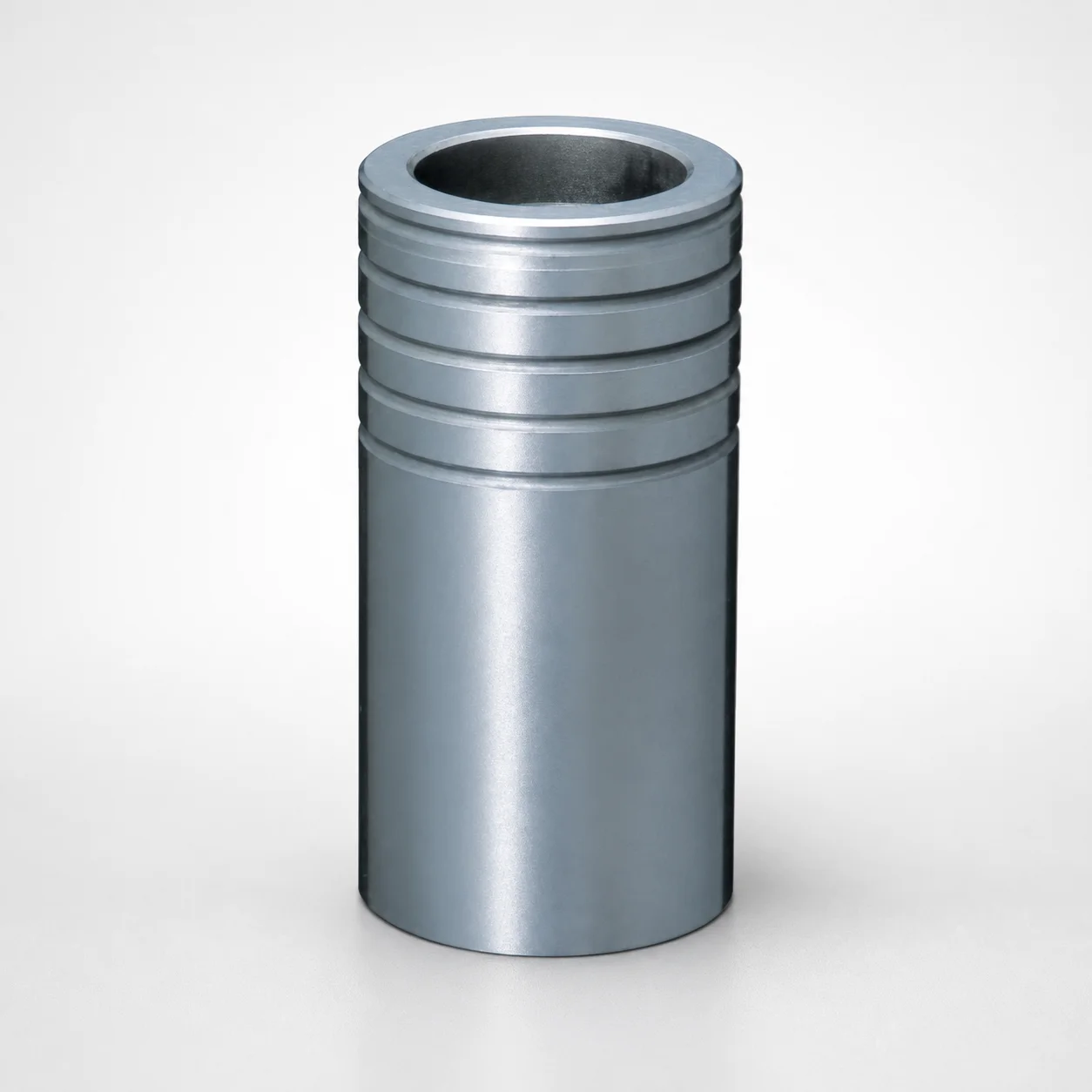
Ball Guide Bushings for Die Sets - Loctite Adhesive LBB Type
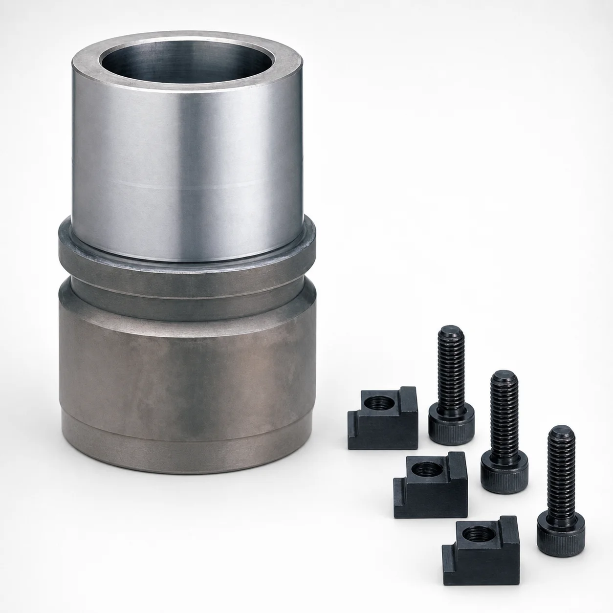
RBB Ball Guide Bushings for Die Sets - Detachable Type
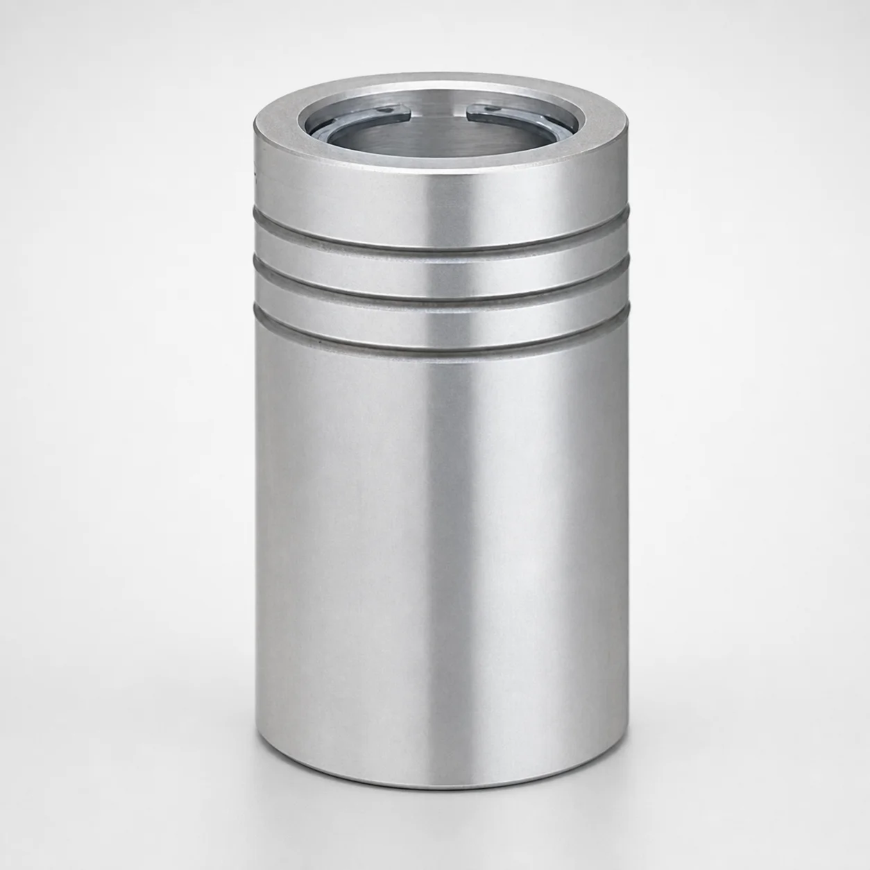
Ball Guide Bushings (LBBS) Loctite Bonded
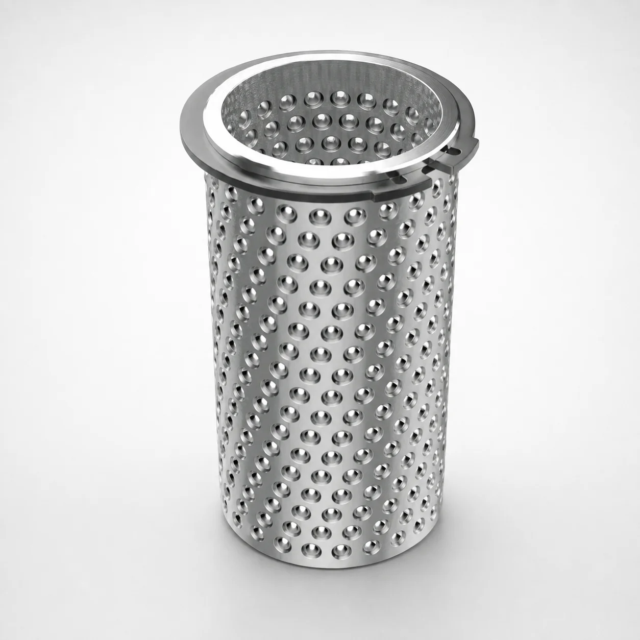
Aluminum Ball Cages for Guide Bushings with Groove & Circlip
Need Custom Specifications?
Our engineering team can help with custom configurations, material selection, and volume pricing.