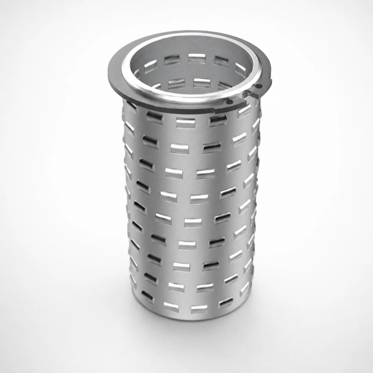
Aluminum Groove Ball Cages for Guide Bushings with Circlip
Aluminum groove ball cages for guide bushings with circlip provide rigid spacing for rolling elements used with DGBI3S, DGBI5S, and DGBI7S assemblies, helping maintain smooth guidance under production load.
- Groove roller cage design improves ball retention and guidance consistency
- Aluminum/steel construction supports stable dimensional performance in die environments
- Circlip installation enables secure cage mounting for repeatable service
- Compatible with DGBI3S, DGBI5S, DGBI7S guide bushing systems
Specifications
62 configurations available
| Length L (mm) | D (Diameter) (mm) | Number of Balls |
|---|---|---|
| 45 | 19 | 40 |
| 55 | 19 | 46 |
| 65 | 19 | 56 |
| 75 | 19 | 64 |
| 45 | 20 | 40 |
| 55 | 20 | 46 |
| 65 | 20 | 56 |
| 75 | 20 | 64 |
| 45 | 24 | 40 |
| 55 | 24 | 48 |
| 65 | 24 | 56 |
| 75 | 24 | 64 |
| 85 | 24 | 72 |
| 45 | 25 | 40 |
| 55 | 25 | 48 |
| 65 | 25 | 56 |
| 75 | 25 | 64 |
| 85 | 25 | 72 |
| 45 | 30 | 48 |
| 55 | 30 | 60 |
| 65 | 30 | 72 |
| 75 | 30 | 84 |
| 85 | 30 | 96 |
| 95 | 30 | 108 |
| 105 | 30 | 120 |
| 45 | 32 | 48 |
| 55 | 32 | 60 |
| 65 | 32 | 72 |
| 75 | 32 | 84 |
| 85 | 32 | 96 |
| 95 | 32 | 108 |
| 105 | 32 | 120 |
| 55 | 38 | 72 |
| 65 | 38 | 84 |
| 75 | 38 | 96 |
| 85 | 38 | 108 |
| 95 | 38 | 120 |
| 105 | 38 | 120 |
| 115 | 38 | 144 |
| 125 | 38 | 156 |
| 55 | 40 | 72 |
| 65 | 40 | 84 |
| 75 | 40 | 96 |
| 85 | 40 | 108 |
| 95 | 40 | 120 |
| 105 | 40 | 120 |
| 115 | 40 | 144 |
| 125 | 40 | 156 |
| 65 | 48 | 105 |
| 75 | 48 | 120 |
Product Guide
Application Scenarios+
This aluminum groove ball cage with circlip is used inside large injection mold or die-casting guide bushing assemblies where rolling-element spacing must remain stable under repeated opening/closing cycles. In practical tooling, it supports the guide balls that carry thrust loads and help maintain straight, low-friction movement of the moving mold plate or slide.
- Die-casting and heavy-duty tooling: The rigid groove-cage spacing helps retain the rolling balls consistently, supporting smoother guidance in high-cycle environments where alignment drift can cause wear.
- Guide bushing systems (DGBI3S / DGBI5S / DGBI7S): The circlip-mounted cage geometry enables secure installation so the cage stays properly located, improving repeatability during service.
- Precision mold base movement: Selecting the correct diameter range (D 19–50 mm) and length (L 45–125 mm) helps match the assembly envelope, keeping ball distribution uniform for reliable guide performance.
Material & Process Details+
The provided specification does not state a specific steel grade, hardness (HRC), or heat-treatment condition. Therefore, material-property claims are limited to the product’s aluminum groove ball cage construction and its role within a guide bushing assembly.
- Material behavior: Aluminum cages are commonly selected in guidance systems where stable dimensional behavior and manageable mass support reliable movement under tooling cycling.
- Manufacturing process (typical for this component type): Groove features are formed to control ball spacing, and the circlip interface is produced to ensure repeatable mounting.
- Selection trade-off: Compared with all-steel cages, aluminum variants can reduce weight and simplify handling, while duty life still depends on the overall guide bushing system design and operating loads.
If you need confirmed metallurgy, hardness, or surface treatment details for this specific MISUMI series, request the material certs for series code 110110366209.
Sizing & Selection Guide+
To select the correct cage for a guide bushing assembly, match the cage diameter D, length L, and ball count to the housing and internal rolling-element specification of the target guide bushing system.
- Diameter (D): Choose within 19–50 mm to fit the guide bushing’s internal envelope and maintain proper ball positioning.
- Length (L): Select within 45–125 mm so the cage fully spans the functional guide zone without under- or over-travel inside the assembly.
- Number of balls: Use the required count from 40–195 to ensure the groove spacing and retention geometry aligns with your ball arrangement.
Install compatibility is supported by the circlip mounting feature, but final fit also depends on your assembly tolerances and the specific DGBI3S, DGBI5S, or DGBI7S design. Where tolerances are critical, verify groove/cage dimensions against the bushing’s datasheet and allow for assembly clearance.
Frequently Asked Questions
How do I choose the correct cage diameter (D 19–50 mm) for DGBI3S, DGBI5S, or DGBI7S guide bushing assemblies?+
What length range (L 45–125 mm) should be used to ensure full ball guidance coverage?+
Does the circlip feature affect how the cage seats in the guide bushing, and what should I verify?+
How does ball count (40–195) influence assembly performance and cage selection?+
Are there multiple material options for series 110110366209, and what material properties are specified?+
Related Products
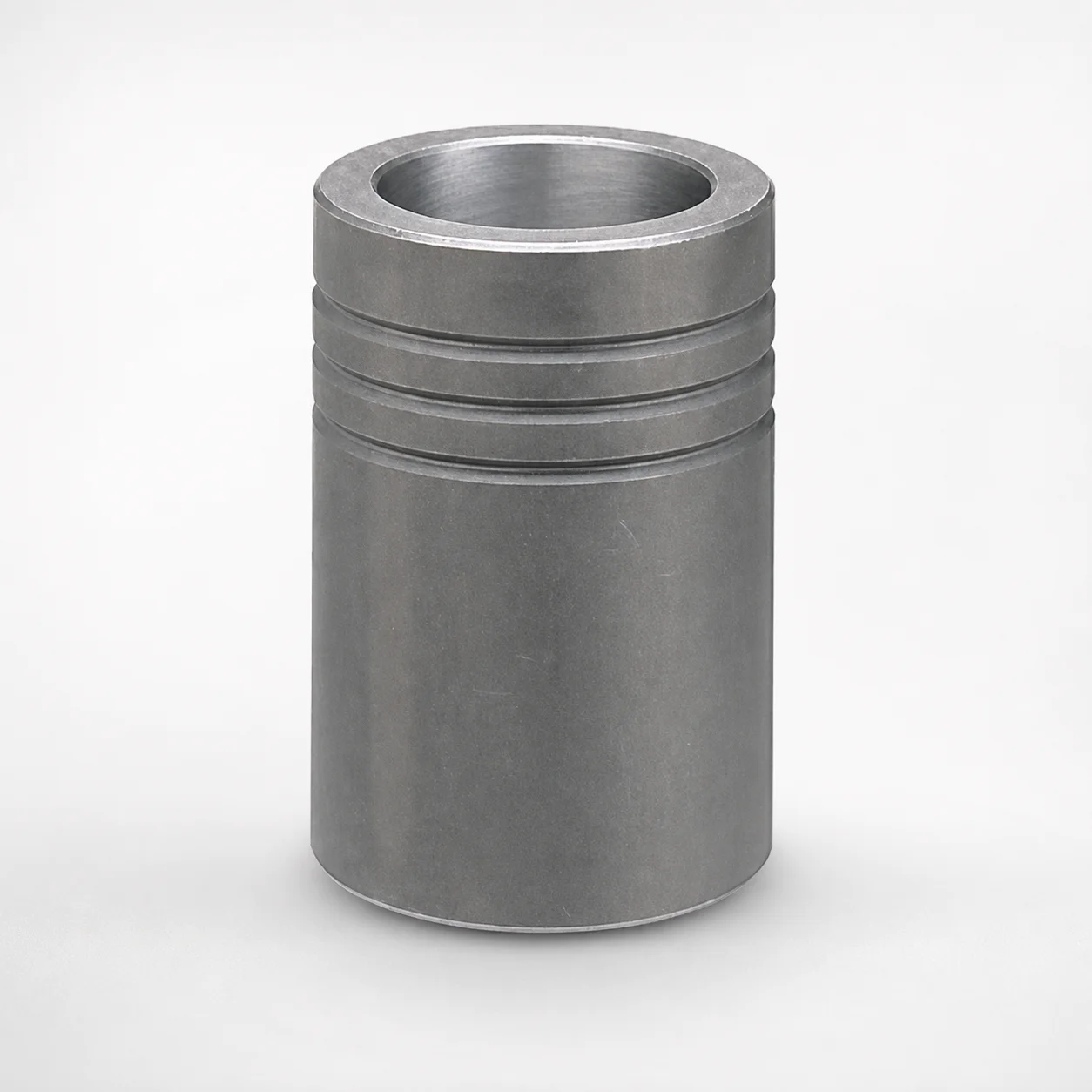
MBB Ball Guide Bushings for Die Sets Bonded by Devcon Adhesive
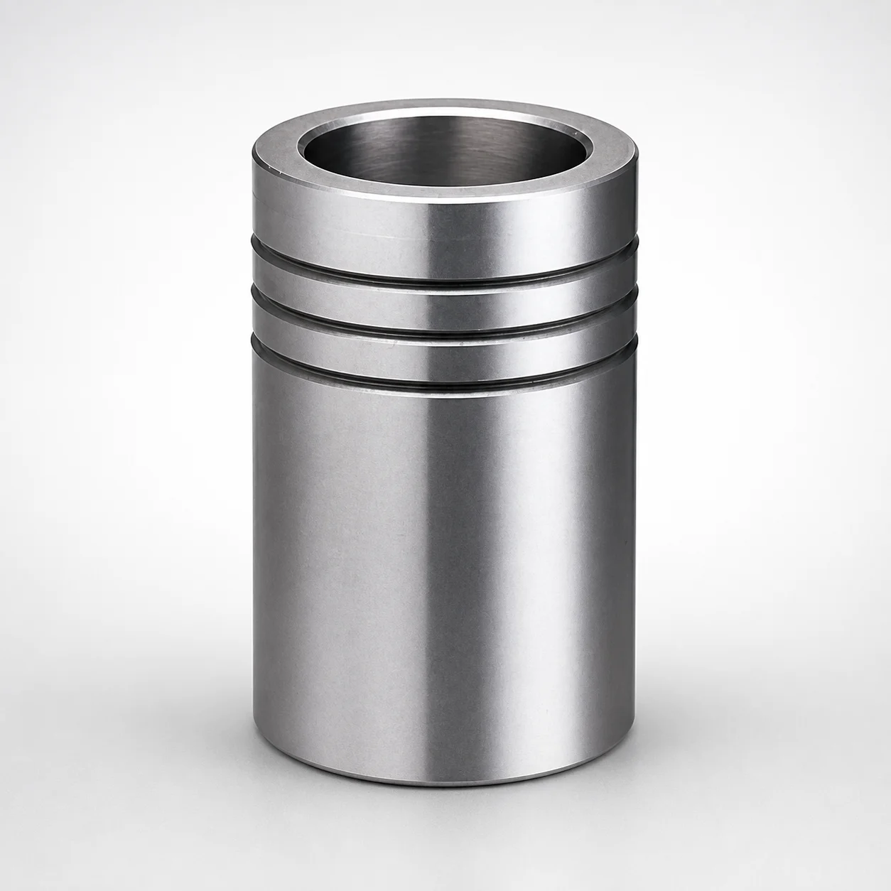
Ball Guide Bushings for Die Sets
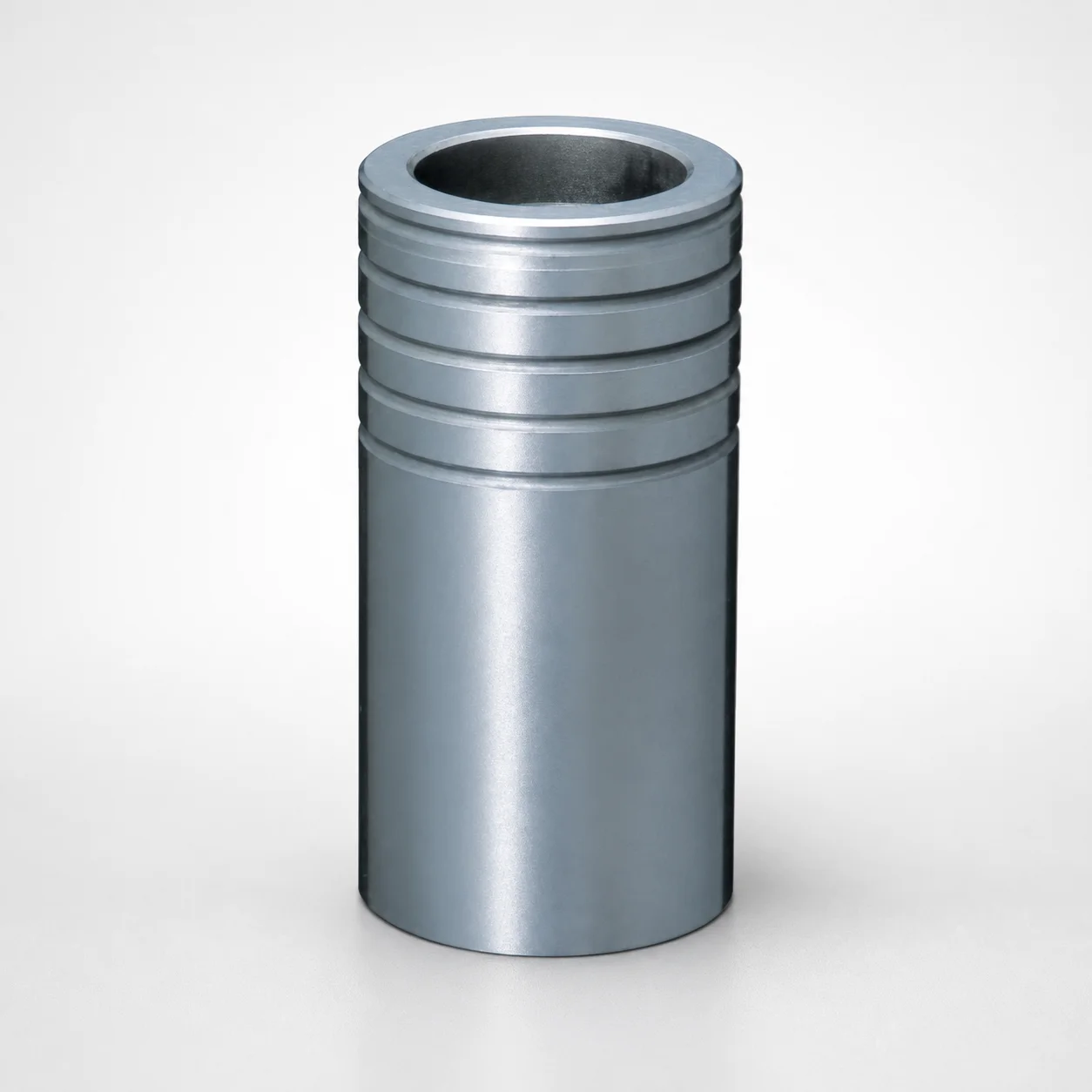
Ball Guide Bushings for Die Sets - Loctite Adhesive LBB Type
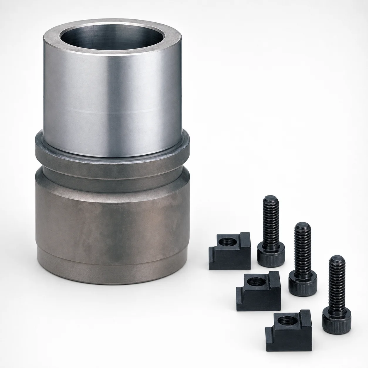
RBB Ball Guide Bushings for Die Sets - Detachable Type
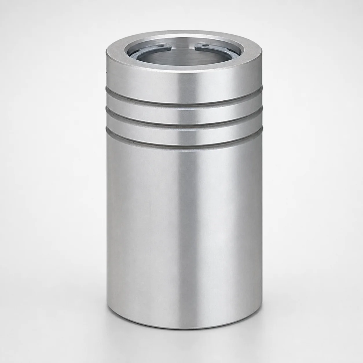
Ball Guide Bushings (LBBS) Loctite Bonded
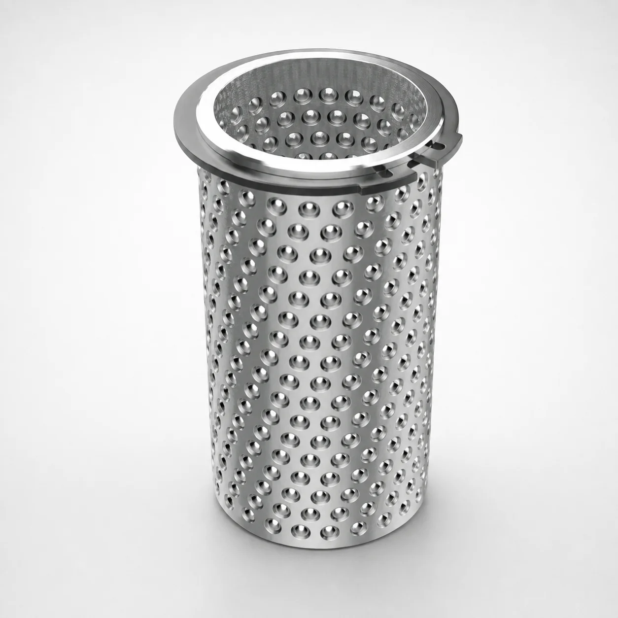
Aluminum Ball Cages for Guide Bushings with Groove & Circlip
Need Custom Specifications?
Our engineering team can help with custom configurations, material selection, and volume pricing.