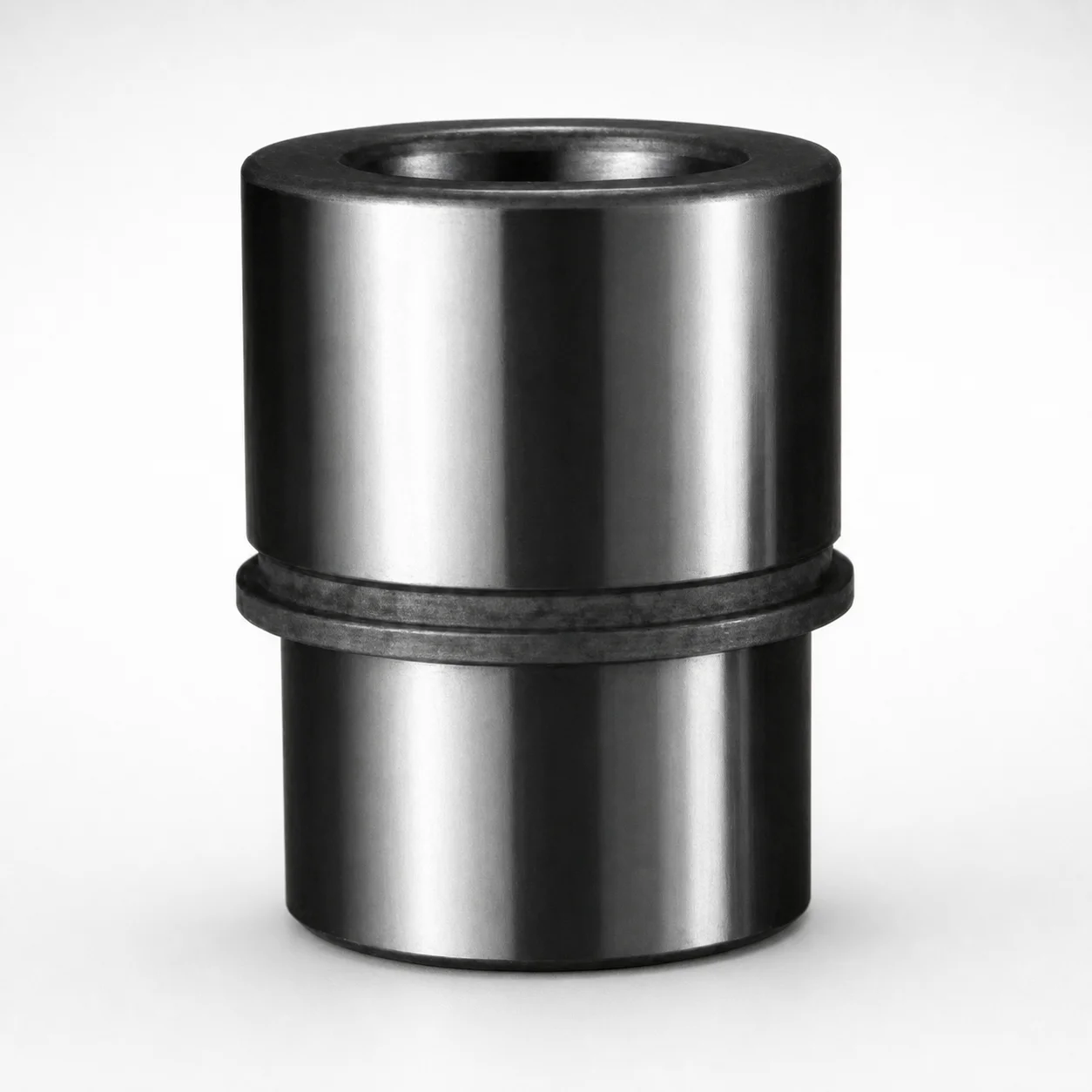
Ball Bearing Ball Guide Bushings (Metric) - Steel
Ball Bearing Ball Guide Bushings (Metric) (Steel) are bushing-only components designed for clamp-mounted guide systems. The ball-guide construction helps maintain stable alignment while supporting smooth operation in die-set and industrial assemblies.
- Ball guide bushing design for controlled motion and alignment
- Steel construction delivers rigidity and reliable service life
- Clamp-mounted interface supports straightforward installation
- Available in multiple pin diameters and L lengths for fit
Specifications
51 configurations available
| Nom. Pin Diameter (mm) | Dimension L1 (mm) |
|---|---|
| 32 | 65 |
| 32 | 70 |
| 32 | 75 |
| 32 | 80 |
| 32 | 85 |
| 32 | 90 |
| 32 | 95 |
| 32 | 105 |
| 32 | 110 |
| 32 | 115 |
| 32 | 130 |
| 32 | 140 |
| 32 | 155 |
| 40 | 75 |
| 40 | 80 |
| 40 | 85 |
| 40 | 90 |
| 40 | 95 |
| 40 | 100 |
| 40 | 110 |
| 40 | 115 |
| 40 | 120 |
| 40 | 125 |
| 40 | 135 |
| 40 | 140 |
| 40 | 155 |
| 50 | 75 |
| 50 | 90 |
| 50 | 95 |
| 50 | 100 |
| 50 | 110 |
| 50 | 115 |
| 50 | 125 |
| 50 | 135 |
| 50 | 140 |
| 50 | 155 |
| 50 | 165 |
| 50 | 180 |
| 50 | 190 |
| 63 | 125 |
| 63 | 140 |
| 63 | 155 |
| 63 | 165 |
| 63 | 180 |
| 63 | 190 |
| 80 | 125 |
| 80 | 140 |
| 80 | 155 |
| 80 | 165 |
| 80 | 180 |
Product Guide
Application Scenarios+
These metric ball guide bushings are used inside clamp-mounted guide systems for large injection molding, die casting, and industrial die-set applications where repeatable alignment is critical. The ball-guide construction promotes smooth, stable motion between mating guide components, helping reduce stick-slip effects and preserving cycle-to-cycle positioning.
In automotive connector and housing molds, the guided alignment helps maintain uniform part geometry during opening/closing, especially when the mold experiences high clamping loads and frequent cycles. The steel construction provides the rigidity needed for long-running service.
For large die-casting tooling, the bushings support controlled motion at the guide interface, improving steadiness during ejection and reducing wear concentration at misaligned contact zones.
- Clamp-mounted assembly: enables straightforward installation into the guide layout.
- Multiple pin diameters and L lengths: lets engineers match the guide stack geometry for proper engagement.
Material & Process Details+
The bushings are supplied in steel, selected to deliver high stiffness for guided clamp-mounted systems. Steel provides a good balance of wear resistance and toughness, helping the ball guide maintain dimensional stability under repeated load cycles.
- Hardness (HRC): not specified in the provided datasheet, so selection should be confirmed against the manufacturer’s material/heat-treatment certificate for the exact series.
- Wear vs. toughness trade-off: for ball-guide duty, higher surface hardness improves resistance to fretting and localized wear, while retained toughness helps prevent chipping or deformation under shock loading.
Heat treatment state (e.g., quenched & tempered, nitrided, or pre-hardened) is not explicitly listed in the provided data. When sourcing for high-wear die casting or high-cycle molding, request the heat-treatment condition and surface treatment details for reliable performance targeting.
Sizing & Selection Guide+
Correct selection is driven by two series-specific variables: the nominal pin diameter and the L length. Choose the nominal pin diameter from 32, 40, 50, 63, or 80 mm to match the guide pin diameter used in your mold guide stack.
- Pin diameter match: select the bushing so its internal fit corresponds to the mating guide pin diameter to ensure controlled ball alignment without excessive clearance.
- Length L: select an L in the range 65 ~ 190 mm to achieve the required guide engagement length within the clamp-mounted housing.
Match the L length to the cavity/core guide design so the bushing supports the full stroke zone where alignment matters (opening/closing and ejection phases). If your design uses tightened fits, confirm the required clearance and tolerances with the guide pin specification; the provided dataset lists only the nominal diameter and L range, so tolerance values should be verified in the series drawing.
These dimensions are configurable within the stated diameter options and the L length range.
Frequently Asked Questions
Which nominal pin diameter options are available for this metric ball guide bushing series?+
This series is offered with nominal pin diameters of 32, 40, 50, 63, or 80 mm. Select the diameter that matches your guide pin to ensure proper ball-guide engagement and alignment.
How do I choose the correct L length (65 ~ 190 mm) for my mold guide engagement?+
Choose L from 65 to 190 mm to cover the guide engagement length needed in your clamp-mounted assembly. Ensure the chosen length supports alignment across the stroke where the die-set positions the core/cavity accurately.
Is this bushing intended for clamp-mounted guide systems only?+
Yes. The component is described as a bushing-only part for clamp-mounted guide systems. This means it is used as part of the guide interface within a larger die-set or industrial assembly.
What steel-related performance details (hardness/heat treatment) should I verify before ordering?+
The provided information states steel construction, but does not list hardness (HRC) or a specific heat-treatment condition. For applications with high wear (e.g., die casting), request the series material/heat-treatment data to confirm surface hardness and toughness.
Can I use these bushings in large die-casting tooling where alignment and motion stability are critical?+
The ball-guide construction is intended to provide stable alignment and smooth guided motion in die-set style assemblies. Since the dataset specifies clamp-mounted usage and provides pin diameter and L range options, you can size the bushing to the guide stack geometry used in your tooling.
Related Products
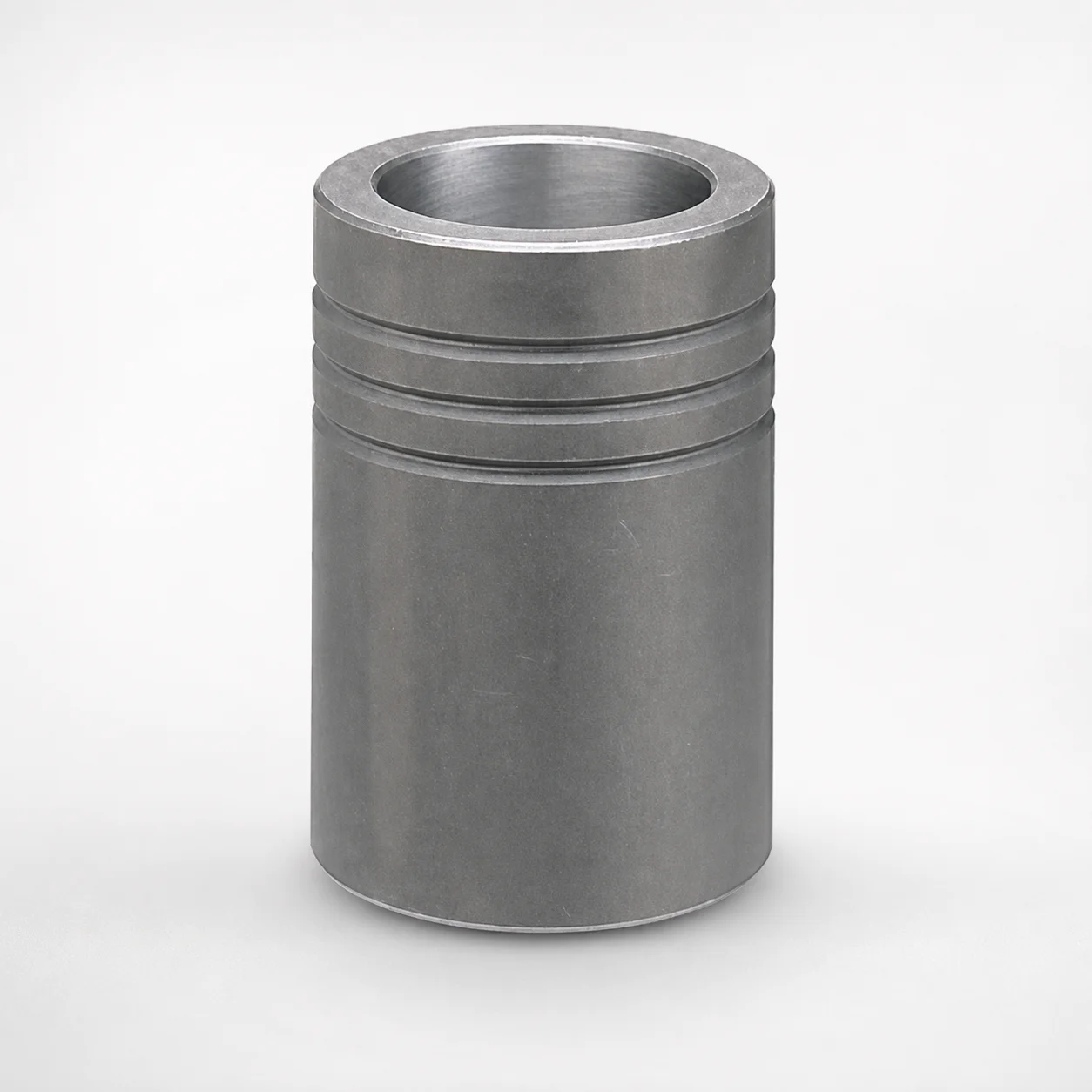
MBB Ball Guide Bushings for Die Sets Bonded by Devcon Adhesive
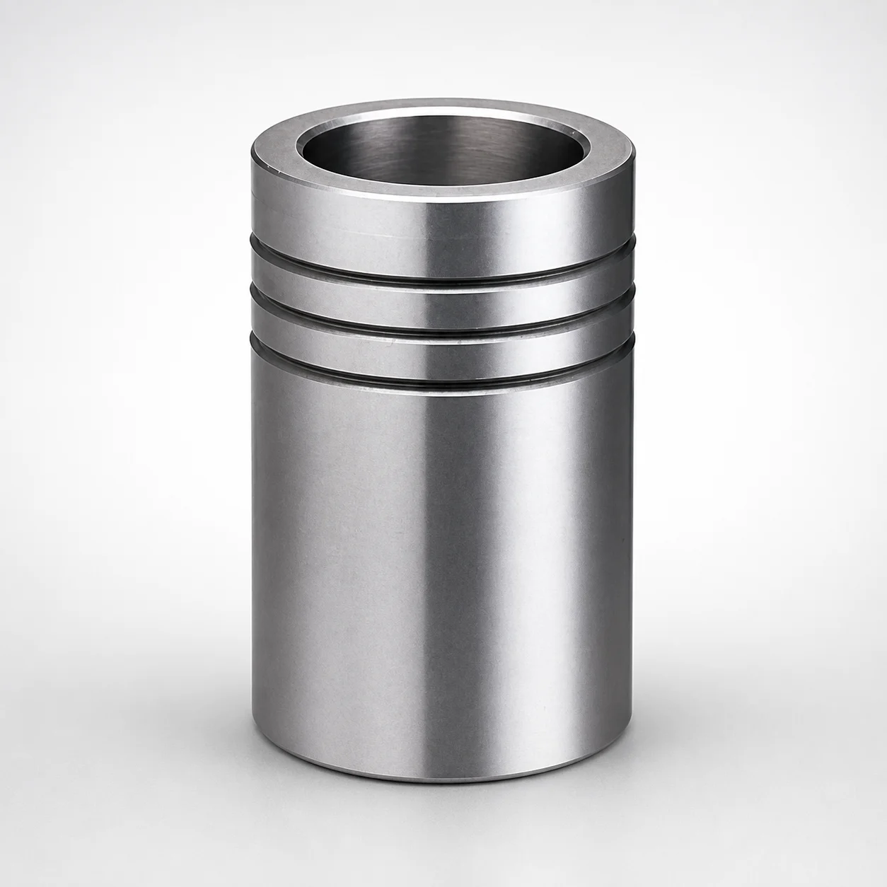
Ball Guide Bushings for Die Sets
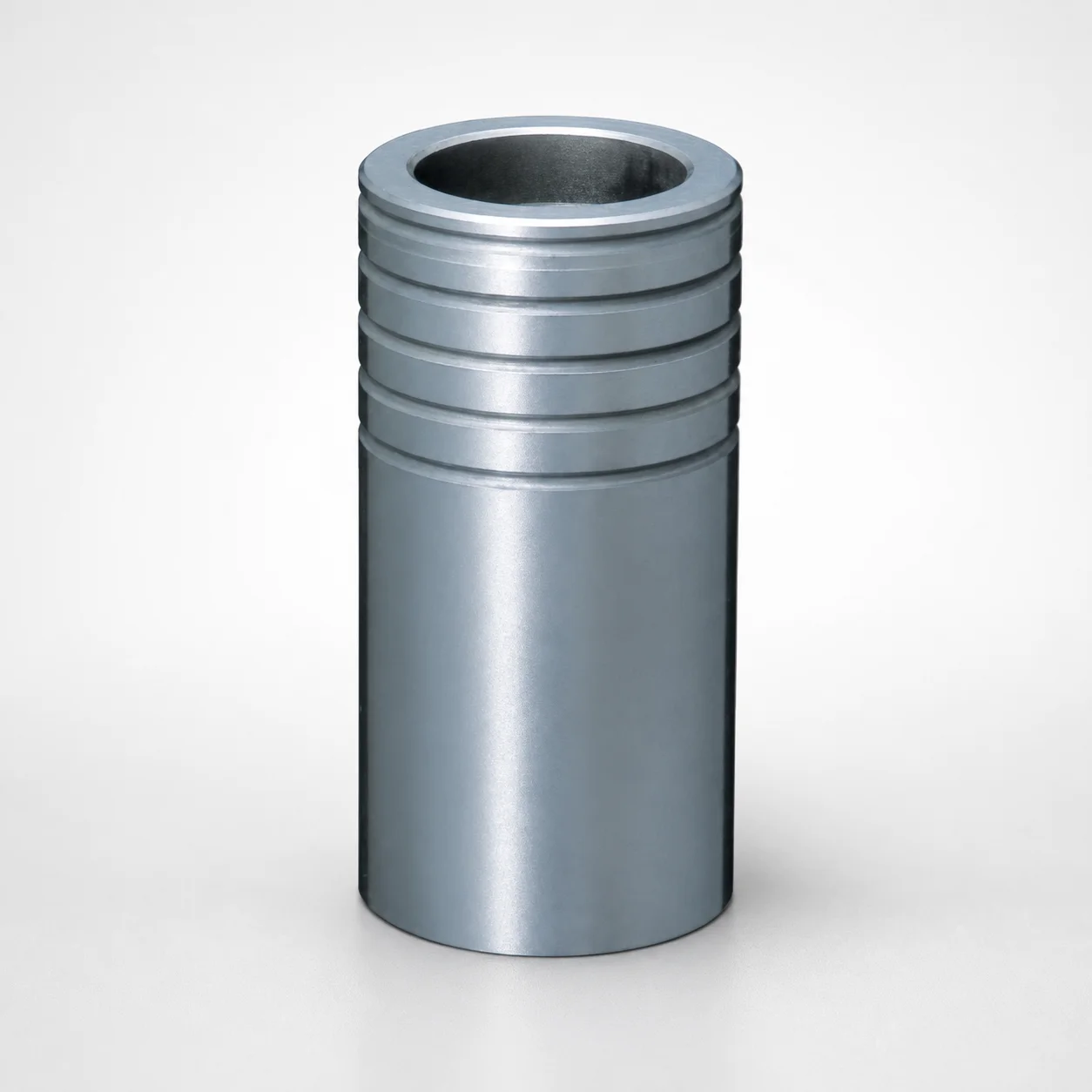
Ball Guide Bushings for Die Sets - Loctite Adhesive LBB Type
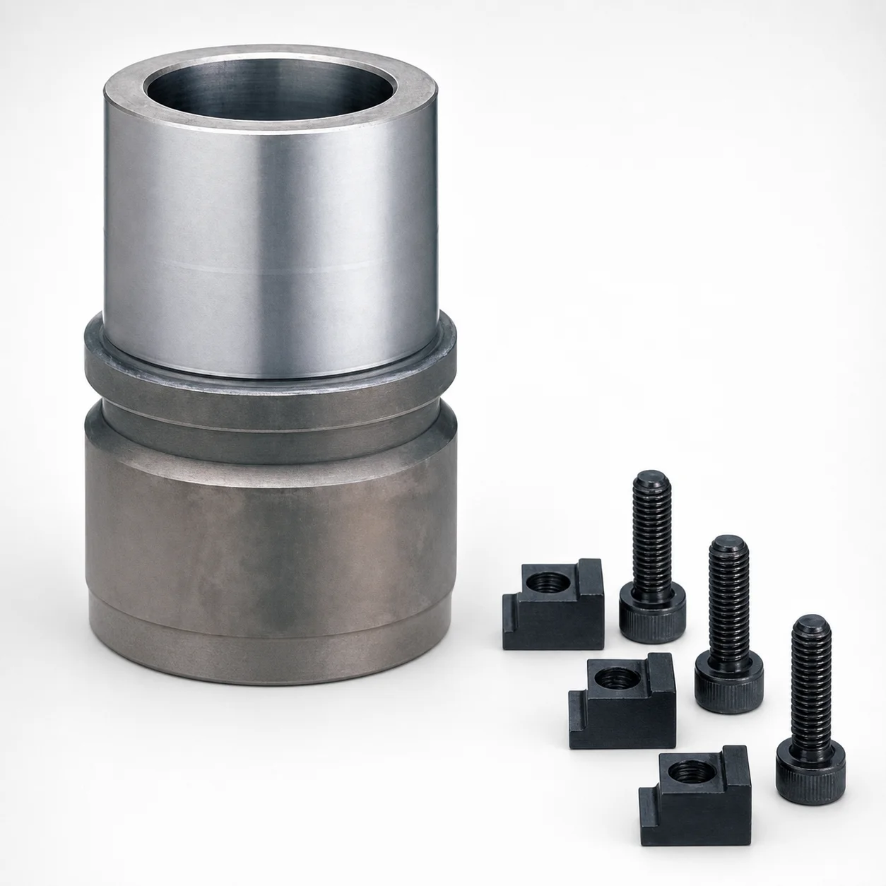
RBB Ball Guide Bushings for Die Sets - Detachable Type
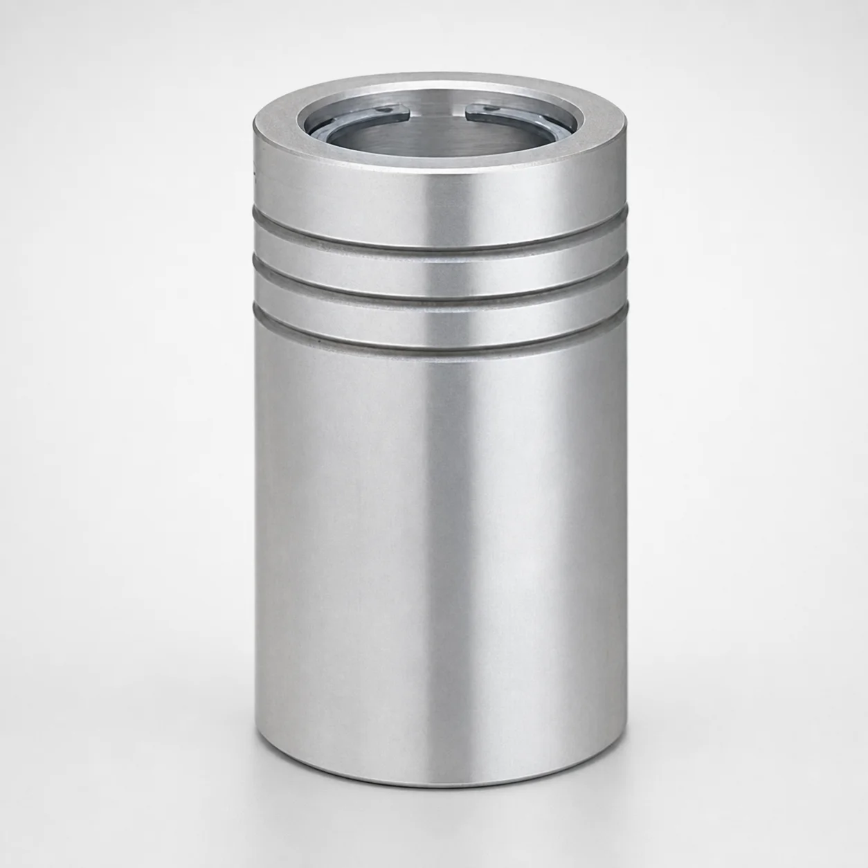
Ball Guide Bushings (LBBS) Loctite Bonded
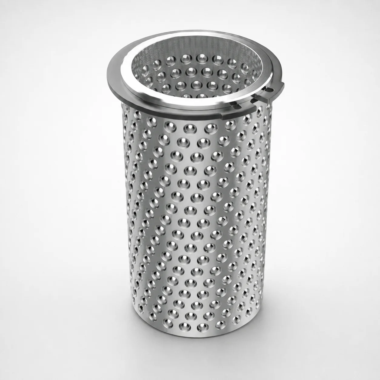
Aluminum Ball Cages for Guide Bushings with Groove & Circlip
Need Custom Specifications?
Our engineering team can help with custom configurations, material selection, and volume pricing.