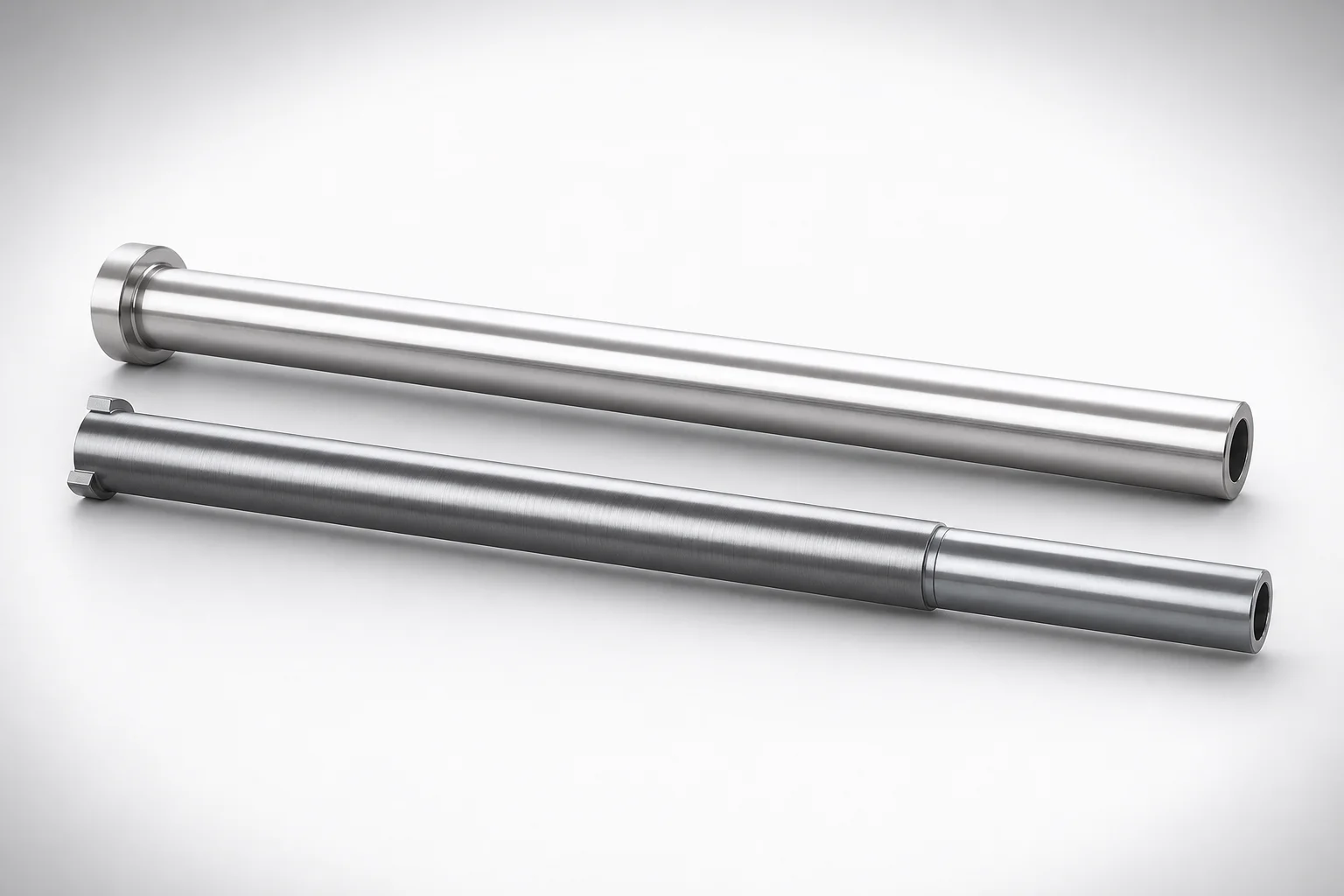
JIS Standard M2 Steel Precision Straight Ejector Sleeves
Precision straight ejector sleeves (M2 steel) are engineered as a single-sleeve component for reliable straight ejection systems, with a JIS-standard head and wire-cut bore finishing for stable fit and alignment.
- Single-sleeve design for consistent straight guiding during mold ejection
- Wire cutting & polishing boring method to produce a smooth, precise bore
- Supports tight inner diameter tolerance references and controlled concentricity
- Made for JIS-head compatibility in standard tooling and precision mold builds
Specifications
64 configurations available
| Head Thickness | Shaft Diameter Tolerance | D/P (Shaft Diameter) (mm) | V (Hole Diameter) (mm) | Boring Method | Shaft diameter designation method | L (L dimension) (mm) | S (V hole diameter length) (mm) | type |
|---|---|---|---|---|---|---|---|---|
| 4mm(T4) | 0/-0.005 | 3.5 | 0.8 ~ 2.3 | Wire cutting & polishing | Shaft diameter selection | 40 ~ 225 | 1 ~ 23 | - |
| 4mm(T4) | 0/-0.005 | 4 | 0.8 ~ 2.8 | Wire cutting & polishing | Shaft diameter selection | 40 ~ 225 | 1 ~ 28 | - |
| 4mm(T4) | 0/-0.005 | 5 | 0.8 ~ 3.8 | Wire cutting & polishing | Shaft diameter selection | 40 ~ 225 | 1 ~ 38 | - |
| 4mm(T4) | 0/-0.005 | 6 | 0.8 ~ 4.8 | Wire cutting & polishing | Shaft diameter selection | 40 ~ 225 | 1 ~ 48 | - |
| 4mm(T4) | 0/-0.005 | 7 | 0.8 ~ 5.8 | Wire cutting & polishing | Shaft diameter selection | 40 ~ 225 | 1 ~ 50 | - |
| 4mm(T4) | 0/-0.005 | 8 | 2 ~ 6.2 | Wire cutting & polishing | Shaft diameter selection | 40 ~ 250 | 1 ~ 50 | - |
| 4mm(T4) | 0/-0.005 | 9 | 2 ~ 7.2 | Wire cutting & polishing | Shaft diameter selection | 40 ~ 250 | 1 ~ 50 | - |
| 4mm(T4) | 0/-0.005 | 10 | 2 ~ 8.2 | Wire cutting & polishing | Shaft diameter selection | 40 ~ 250 | 1 ~ 50 | - |
| 4mm(T4) | 0/-0.005 | 11 | 2 ~ 9.2 | Wire cutting & polishing | Shaft diameter selection | 40 ~ 250 | 1 ~ 50 | - |
| 4mm(T4) | 0/-0.005 | 12 | 2 ~ 10.2 | Wire cutting & polishing | Shaft diameter selection | 40 ~ 250 | 1 ~ 50 | - |
| 4mm(T4) | 0/-0.005 | 13 | 2 ~ 11.2 | Wire cutting & polishing | Shaft diameter selection | 40 ~ 250 | 1 ~ 50 | - |
| 4mm(T4) | 0/-0.005 | 14 | 2 ~ 12.2 | Wire cutting & polishing | Shaft diameter selection | 40 ~ 250 | 1 ~ 50 | - |
| 4mm(T4) | -0.01/-0.02 | 3.5 | 0.8 ~ 2.3 | - | Shaft diameter selection | 40 ~ 225 | 1 ~ 23 | - |
| 4mm(T4) | -0.01/-0.02 | 4 | 0.8 ~ 2.8 | - | Shaft diameter selection | 40 ~ 225 | 1 ~ 28 | - |
| 4mm(T4) | -0.01/-0.02 | 5 | 0.8 ~ 3.8 | - | Shaft diameter selection | 40 ~ 225 | 1 ~ 38 | - |
| 4mm(T4) | -0.01/-0.02 | 6 | 0.8 ~ 4.8 | - | Shaft diameter selection | 40 ~ 225 | 1 ~ 48 | - |
| 4mm(T4) | -0.01/-0.02 | 7 | 0.8 ~ 5.8 | - | Shaft diameter selection | 40 ~ 225 | 1 ~ 50 | - |
| 4mm(T4) | -0.01/-0.02 | 8 | 2 ~ 6.2 | - | Shaft diameter selection | 40 ~ 250 | 1 ~ 50 | - |
| 4mm(T4) | -0.01/-0.02 | 9 | 2 ~ 7.2 | - | Shaft diameter selection | 40 ~ 250 | 1 ~ 50 | - |
| 4mm(T4) | -0.01/-0.02 | 10 | 2 ~ 8.2 | - | Shaft diameter selection | 40 ~ 250 | 1 �� 50 | - |
| 4mm(T4) | -0.01/-0.02 | 11 | 2 ~ 9.2 | - | Shaft diameter selection | 40 ~ 250 | 1 ~ 50 | - |
| 4mm(T4) | -0.01/-0.02 | 12 | 2 ~ 10.2 | - | Shaft diameter selection | 40 ~ 250 | 1 ~ 50 | - |
| 4mm(T4) | -0.01/-0.02 | 13 | 2 ~ 11.2 | - | Shaft diameter selection | 40 ~ 250 | 1 ~ 50 | - |
| 4mm(T4) | -0.01/-0.02 | 14 | 2 ~ 12.2 | - | Shaft diameter selection | 40 ~ 250 | 1 ~ 50 | - |
| 4mm(T4) | 0/-0.005 | 3.2 ~ 3.99 | 0.8 ~ 2.79 | Wire cutting & polishing | Shaft diameter 0.01mm increments | 40 ~ 225 | 1 ~ 27.5 | - |
| 4mm(T4) | 0/-0.005 | 4 ~ 4.99 | 0.8 ~ 3.79 | Wire cutting & polishing | Shaft diameter 0.01mm increments | 40 ~ 225 | 1 ~ 37.5 | - |
| 4mm(T4) | 0/-0.005 | 5 ~ 5.99 | 0.8 ~ 4.79 | Wire cutting & polishing | Shaft diameter 0.01mm increments | 40 ~ 225 | 1 ~ 47.5 | - |
| 4mm(T4) | 0/-0.005 | 6 ~ 6.99 | 0.8 ~ 5.79 | Wire cutting & polishing | Shaft diameter 0.01mm increments | 40 ~ 225 | 1 ~ 50 | - |
| 4mm(T4) | 0/-0.005 | 7 ~ 7.99 | 2 ~ 6.19 | Wire cutting & polishing | Shaft diameter 0.01mm increments | 40 ~ 250 | 1 ~ 50 | - |
| 4mm(T4) | 0/-0.005 | 8 ~ 8.99 | 2 ~ 7.19 | Wire cutting & polishing | Shaft diameter 0.01mm increments | 40 ~ 250 | 1 ~ 50 | - |
| 4mm(T4) | 0/-0.005 | 9 ~ 9.99 | 2 ~ 8.19 | Wire cutting & polishing | Shaft diameter 0.01mm increments | 40 ~ 250 | 1 ~ 50 | - |
| 4mm(T4) | 0/-0.005 | 10 ~ 10.99 | 2 ~ 9.19 | Wire cutting & polishing | Shaft diameter 0.01mm increments | 40 ~ 250 | 1 ~ 50 | - |
| 4mm(T4) | 0/-0.005 | 11 ~ 11.99 | 2 ~ 10.19 | Wire cutting & polishing | Shaft diameter 0.01mm increments | 40 ~ 250 | 1 ~ 50 | - |
| 4mm(T4) | 0/-0.005 | 12 ~ 12.99 | 2 ~ 11.19 | Wire cutting & polishing | Shaft diameter 0.01mm increments | 40 ~ 250 | 1 ~ 50 | - |
| 4mm(T4) | 0/-0.005 | 13 ~ 13.99 | 2 ~ 12.19 | Wire cutting & polishing | Shaft diameter 0.01mm increments | 40 ~ 250 | 1 ~ 50 | - |
| 4mm(T4) | -0.01/-0.02 | 3.2 ~ 3.99 | 0.8 ~ 2.79 | - | Shaft diameter 0.01mm increments | 40 ~ 225 | 1 ~ 27.5 | - |
| 4mm(T4) | -0.01/-0.02 | 4 ~ 4.99 | 0.8 ~ 3.79 | - | Shaft diameter 0.01mm increments | 40 ~ 225 | 1 ~ 37.5 | - |
| 4mm(T4) | -0.01/-0.02 | 5 ~ 5.99 | 0.8 ~ 4.79 | - | Shaft diameter 0.01mm increments | 40 ~ 225 | 1 ~ 47.5 | - |
| 4mm(T4) | -0.01/-0.02 | 6 ~ 6.99 | 0.8 ~ 5.79 | - | Shaft diameter 0.01mm increments | 40 ~ 225 | 1 ~ 50 | - |
| 4mm(T4) | -0.01/-0.02 | 7 ~ 7.99 | 2 ~ 6.19 | - | Shaft diameter 0.01mm increments | 40 ~ 250 | 1 ~ 50 | - |
| 4mm(T4) | -0.01/-0.02 | 8 ~ 8.99 | 2 ~ 7.19 | - | Shaft diameter 0.01mm increments | 40 ~ 250 | 1 ~ 50 | - |
| 4mm(T4) | -0.01/-0.02 | 9 ~ 9.99 | 2 ~ 8.19 | - | Shaft diameter 0.01mm increments | 40 ~ 250 | 1 ~ 50 | - |
| 4mm(T4) | -0.01/-0.02 | 10 ~ 10.99 | 2 ~ 9.19 | - | Shaft diameter 0.01mm increments | 40 ~ 250 | 1 ~ 50 | - |
| 4mm(T4) | -0.01/-0.02 | 11 ~ 11.99 | 2 ~ 10.19 | - | Shaft diameter 0.01mm increments | 40 ~ 250 | 1 ~ 50 | - |
| 4mm(T4) | -0.01/-0.02 | 12 ~ 12.99 | 2 ~ 11.19 | - | Shaft diameter 0.01mm increments | 40 ~ 250 | 1 ~ 50 | - |
| 4mm(T4) | -0.01/-0.02 | 13 ~ 13.99 | 2 ~ 12.19 | - | Shaft diameter 0.01mm increments | 40 ~ 250 | 1 ~ 50 | - |
| 6mm(JIS) | 0/-0.005 | 6 | 0.8 ~ 4.8 | Wire cutting & polishing | Shaft diameter selection | 40 ~ 225 | 1 ~ 48 | - |
| 6mm(JIS) | 0/-0.005 | 7 | 0.8 ~ 5.8 | Wire cutting & polishing | Shaft diameter selection | 40 ~ 225 | 1 ~ 50 | - |
| 8mm(JIS) | 0/-0.005 | 8 | 2 ~ 6.2 | Wire cutting & polishing | Shaft diameter selection | 40 ~ 250 | 1 ~ 50 | - |
| 8mm(JIS) | 0/-0.005 | 9 | 2 ~ 7.2 | Wire cutting & polishing | Shaft diameter selection | 40 ~ 250 | 1 ~ 50 | - |
Product Guide
Application Scenarios+
This precision straight ejector sleeve is used inside injection mold ejector systems where straight guiding is critical for stable part release and consistent ejection force transmission. The single-sleeve layout supports straight-line motion during high-cycle mold operation, helping maintain alignment between the ejector pin and the surrounding components.
In automotive connector and sensor housing molds, the wire-cut and polished bore finish helps achieve smooth sliding under repeated start/stop conditions, reducing stick-slip and promoting uniform ejection across multiple cavities.
For consumer electronics and slim enclosure parts, the sleeve’s tight inner diameter tolerance options (e.g., 0/-0.005 to -0.01/-0.02 style selections) are suited to designs that demand controlled clearance and concentricity at small shaft diameters (3.2–14 mm).
- Choose the variant matching your required head thickness (4 mm, 6 mm, or 8 mm) for reliable seating and load transfer.
- Select V (hole diameter) and L (length) from the available ranges to match your ejector pin guide geometry.
Material & Process Details+
This component is specified as JIS Standard M2 steel for precision wear resistance in ejector guide applications. In practical terms, M2 is commonly associated with the high-speed steel family used for tooling components requiring good hardness and abrasion resistance.
Because the bore is produced by wire cutting & polishing, the steel’s ability to hold a tight geometry after heat treatment is important for long-term dimensional stability and smooth sliding.
- Hardness: For M2 (HSS), typical heat-treated hardness is often around the mid-to-high HRC range depending on supplier process, balancing wear resistance and toughness.
- Trade-off: Higher hardness improves wear resistance but can reduce toughness if used beyond recommended tempering practice.
- Heat treatment state: Usually provided in a precision-machined, heat-treated condition (commonly quenched and tempered) suitable for fine-bore guiding.
Sizing & Selection Guide+
Start by matching the sleeve to the ejector pin shaft size. The available shaft diameter (D/P) range is 3.2 to 14 mm, and the sleeve supports 0.01 mm increments for shaft diameter selection.
Select the hole diameter (V) from 0.8 to 2 mm and confirm the tolerance style you require: available shaft diameter tolerance selections include 0/-0.005 and -0.01/-0.02 style options (use the tighter selection when you need controlled clearance).
Then choose length L from 40–225 mm or 40–250 mm depending on configuration, and verify the S (V hole diameter length) is 1 mm (fixed in the provided specification set).
- Match head thickness to your tooling: options are T4 = 4 mm, and JIS head thickness of 6 mm or 8 mm.
- Use the tolerance selection to manage running clearance and ensure smooth ejection without binding.
Frequently Asked Questions
Which shaft diameter range and tolerance styles are available for this JIS M2 precision straight ejector sleeve?+
How do I select the correct head thickness for proper seating in an ejector system?+
What bore finishing method is used, and why does it matter for sliding performance?+
What are the available lengths (L) and fixed dimensions for V-hole length (S) in this sleeve?+
Is the hole diameter V variable, and what impact does it have on clearance with the ejector pin?+
Related Products
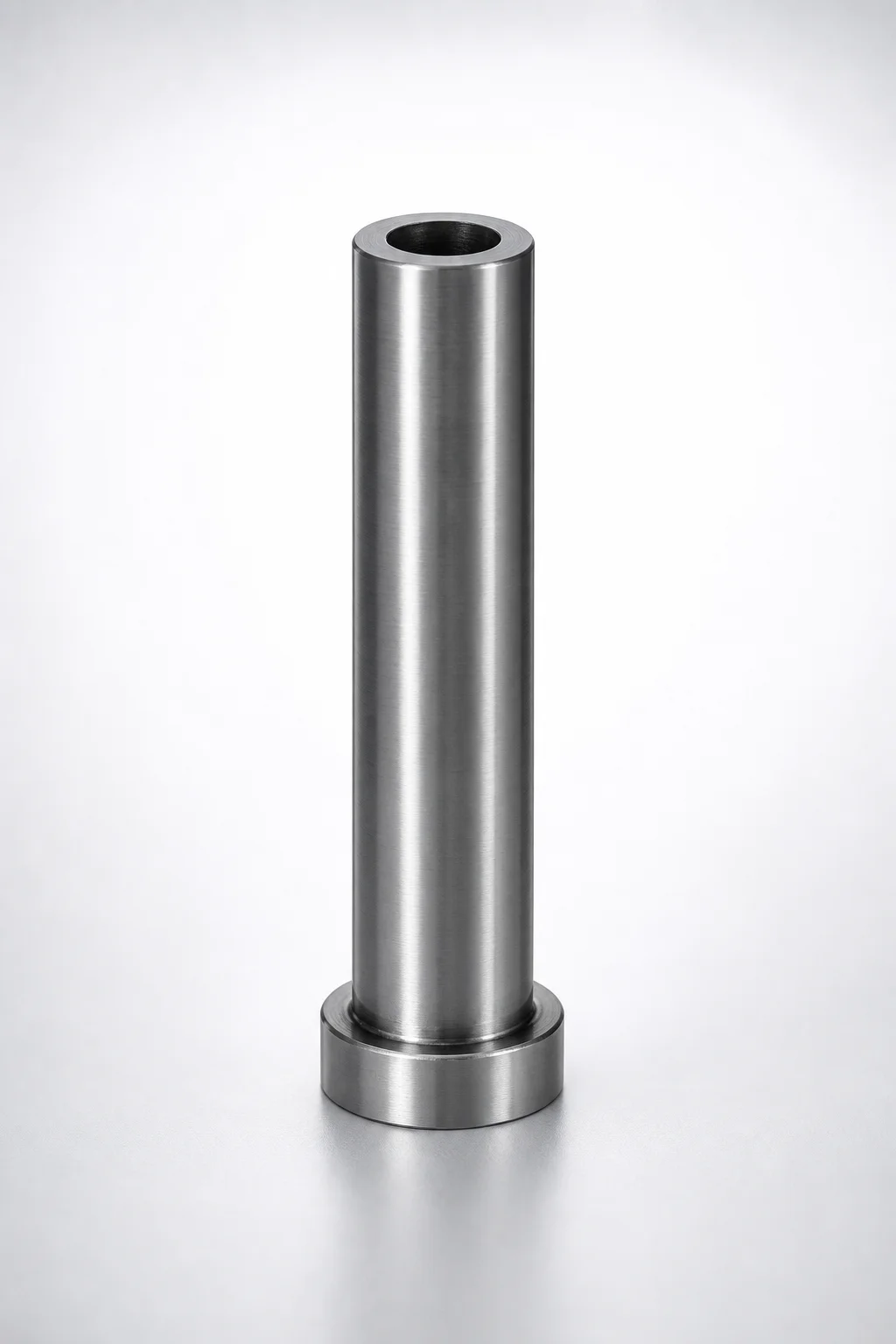
SKD61 Steel Short Straight Ejector Sleeves with Nitride Coating - Head T4
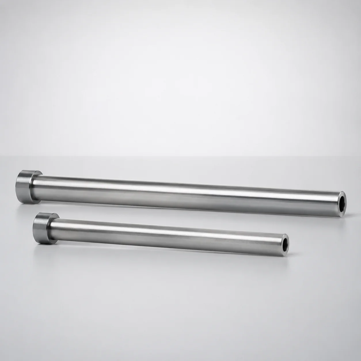
SKD61 Steel Nitrided Straight Ejector Sleeves (ESNV) Head T=4 mm
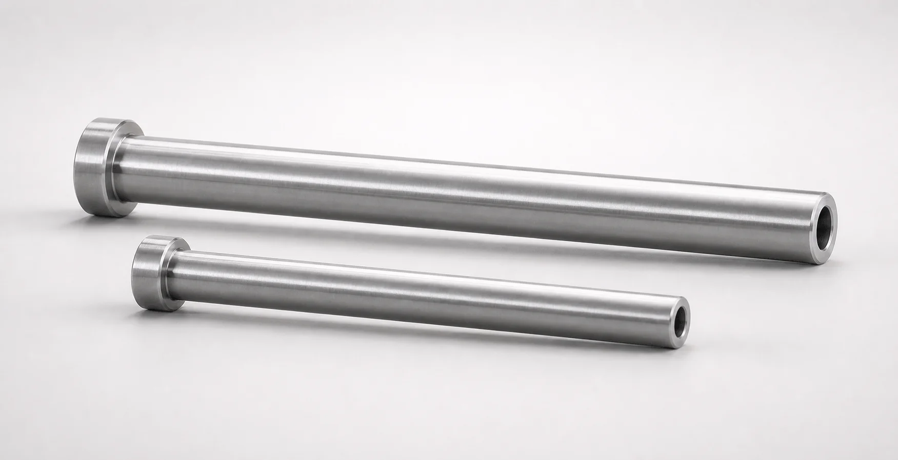
SKD61 Steel Nitrided Straight Ejector Sleeves
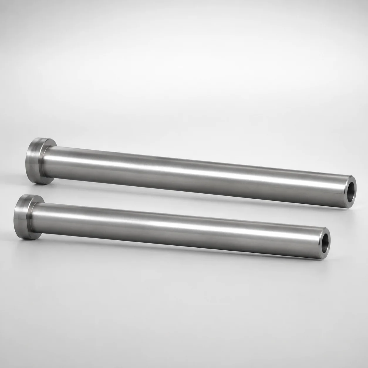
SKD61 Steel Nitrided Straight Ejector Sleeves Head T4
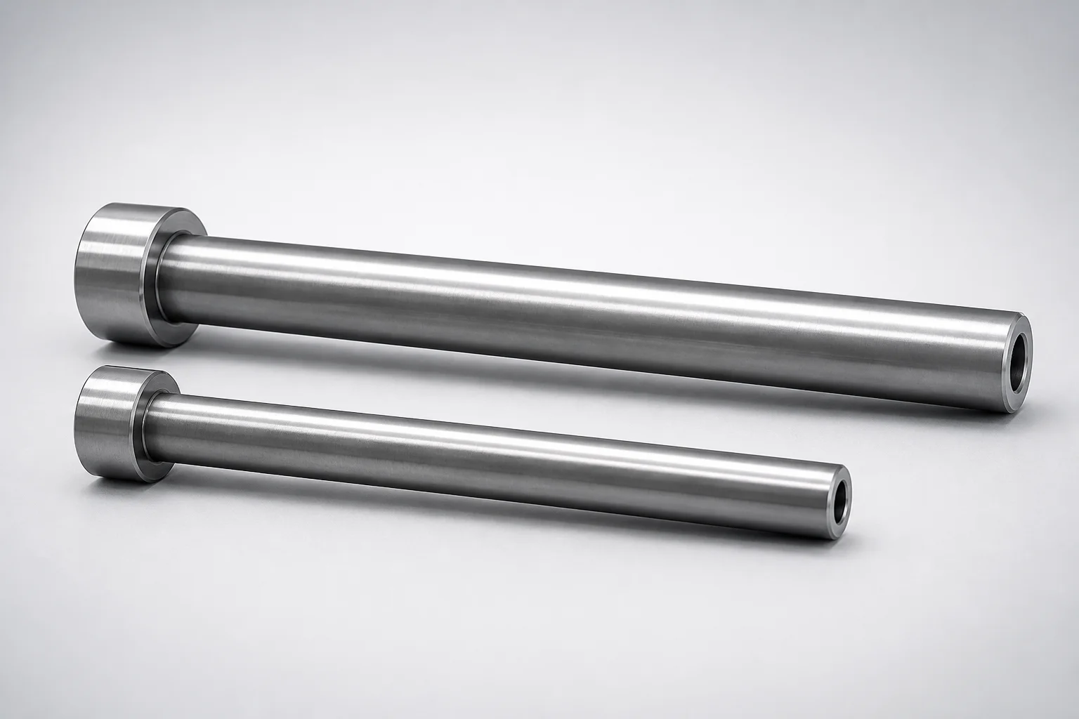
JIS Standard SKD61 Steel Nitrided Straight Ejector Sleeves H7 Bore
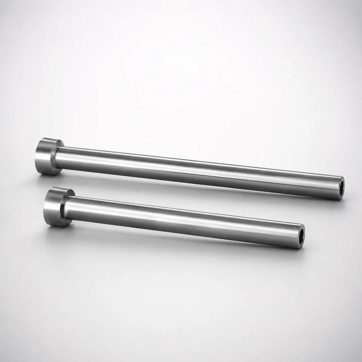
SKD61 Steel Nitrided Straight Ejector Sleeves
Need Custom Specifications?
Our engineering team can help with custom configurations, material selection, and volume pricing.