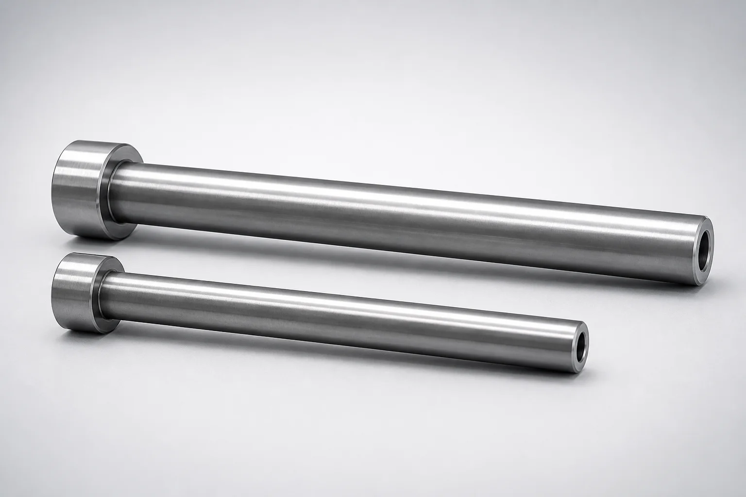
JIS Standard SKD61 Steel Nitrided Straight Ejector Sleeves H7 Bore
Straight ejector sleeves (SKD61 steel) are nitrided for improved wear resistance and designed with a JIS head geometry for reliable guiding in mold ejection systems. The H7 inner-bore tolerance supports consistent alignment and smooth sleeve performance under repeated cycles.
- Single-sleeve construction for stable concentric guiding in ejector applications
- Nitrided (case-hardened) SKD61 steel offers enhanced abrasion resistance
- Controlled H7 inner diameter tolerance supports precise fit and repeatability
- Built to JIS head specifications for compatibility with standard mold components
Specifications
26 configurations available
| Head Thickness | D/P (Shaft Diameter) (mm) | V (Hole Diameter) (mm) | Shaft diameter designation method | L (L dimension) (mm) | C (Recess diameter) (mm) | S (V hole diameter length) (mm) | type |
|---|---|---|---|---|---|---|---|
| 6mm(JIS) | 3.5 ~ 3.99 | 1.5 ~ 1.9 | Shaft diameter 0.01mm increments | 40 ~ 200 | 2 ~ 2.5 | 20 ~ 40 | - |
| 6mm(JIS) | 4.01 ~ 4.49 | 1.5 ~ 2.4 | Shaft diameter 0.01mm increments | 40 ~ 250 | 2 ~ 3 | 20 ~ 50 | - |
| 6mm(JIS) | 4.51 ~ 4.99 | 2 ~ 2.9 | Shaft diameter 0.01mm increments | 40 ~ 300 | 2.5 ~ 3.5 | 20 ~ 50 | - |
| 6mm(JIS) | 5.01 ~ 5.49 | 2 ~ 3.4 | Shaft diameter 0.01mm increments | 40 ~ 300 | 2.5 ~ 4 | 20 ~ 50 | - |
| 6mm(JIS) | 5.51 ~ 5.99 | 2 ~ 3.9 | Shaft diameter 0.01mm increments | 40 ~ 300 | 2.5 ~ 4.5 | 20 ~ 50 | - |
| 6mm(JIS) | 6.01 ~ 6.49 | 2 ~ 4.4 | Shaft diameter 0.01mm increments | 40 ~ 300 | 2.5 ~ 5 | 20 ~ 50 | - |
| 6mm(JIS) | 6.51 ~ 6.99 | 2 ~ 4.9 | Shaft diameter 0.01mm increments | 40 ~ 300 | 2.5 ~ 5.5 | 20 ~ 50 | - |
| 6mm(JIS) | 7.01 ~ 7.49 | 2 ~ 5.4 | Shaft diameter 0.01mm increments | 40 ~ 300 | 2.5 ~ 6 | 20 ~ 50 | - |
| 8mm(JIS) | 7.51 ~ 7.99 | 2.5 ~ 5.9 | Shaft diameter 0.01mm increments | 40 ~ 300 | 3 ~ 6.5 | 20 ~ 50 | - |
| 8mm(JIS) | 8.01 ~ 9.99 | 2.5 ~ 7.9 | Shaft diameter 0.01mm increments | 40 ~ 300 | 3 ~ 8.5 | 20 ~ 50 | - |
| 6mm(JIS) | 4 | 1.5 ~ 2.5 | Shaft diameter selection | 40 ~ 200 | 2 ~ 3 | 20 ~ 50 | - |
| 6mm(JIS) | 4.5 | 1.5 ~ 2.5 | Shaft diameter selection | 40 ~ 250 | 2 ~ 3 | 20 ~ 50 | - |
| 6mm(JIS) | 5 | 2 ~ 3 | Shaft diameter selection | 40 ~ 300 | 2.5 ~ 3.5 | 20 ~ 50 | - |
| 6mm(JIS) | 5.5 | 2 ~ 3.5 | Shaft diameter selection | 40 ~ 300 | 2.5 ~ 4 | 20 ~ 50 | - |
| 6mm(JIS) | 6 | 2 ~ 4 | Shaft diameter selection | 40 ~ 300 | 2.5 ~ 4.5 | 20 ~ 50 | - |
| 6mm(JIS) | 6 | 2 ~ 4 | Shaft diameter selection | 40 ~ 300 | 2.5 ~ 4.5 | 20 ~ 50 | - |
| 6mm(JIS) | 6.5 | 2.5 ~ 4.5 | Shaft diameter selection | 40 ~ 300 | 3 ~ 5 | 20 ~ 50 | - |
| 6mm(JIS) | 6.5 | 2.5 ~ 4.5 | Shaft diameter selection | 40 ~ 300 | 3 ~ 5 | 20 ~ 50 | - |
| 6mm(JIS) | 7 | 2.5 ~ 4.5 | Shaft diameter selection | 40 ~ 300 | 3 ~ 5 | 20 ~ 50 | - |
| 6mm(JIS) | 7 | 2.5 ~ 4.5 | Shaft diameter selection | 40 ~ 300 | 3 ~ 5 | 20 ~ 50 | - |
| 6mm(JIS) | 7.5 | 2.5 ~ 5 | Shaft diameter selection | 40 ~ 300 | 3 ~ 5.5 | 20 ~ 50 | - |
| 6mm(JIS) | 7.5 | 2.5 ~ 5 | Shaft diameter selection | 40 ~ 300 | 3 ~ 5.5 | 20 ~ 50 | - |
| 8mm(JIS) | 8 | 2.5 ~ 5.5 | Shaft diameter selection | 40 ~ 300 | 3 ~ 6 | 20 ~ 50 | - |
| 8mm(JIS) | 9 | 2.5 ~ 6.5 | Shaft diameter selection | 40 ~ 300 | 3 ~ 7 | 20 ~ 50 | - |
| 8mm(JIS) | 10 | 4 ~ 7.5 | Shaft diameter selection | 40 ~ 300 | 4.5 ~ 8 | 20 ~ 50 | - |
| 8mm(JIS) | 10 | 4 ~ 7.5 | Shaft diameter selection | 40 ~ 300 | 4.5 ~ 8 | 20 ~ 50 | - |
Product Guide
Application Scenarios+
Straight ejector sleeves are used inside injection mold bases to guide ejector pins and distribute movement smoothly during opening and ejection. This SKD61 nitrided, JIS-head variant is suited for production molds where stable alignment and resistance to abrasive wear are critical.
In automotive connector and housing molds, repeated short-cycle ejection can polish or scuff sliding surfaces. The nitrided SKD61 case improves surface wear behavior, while the H7 inner-bore tolerance helps maintain consistent press-fit alignment with guiding pins.
For consumer electronics and appliance parts (e.g., snap-fit covers and brackets), ejector systems must stay concentric to avoid sticking and uneven part release. The JIS head geometry supports compatibility with standard ejector sleeve retaining features, reducing assembly variability.
- Use when stable guiding under repeated cycles is required
- Choose the correct bore tolerance (H7) for predictable fit
- Ideal where wear from ejector pin sliding is a primary concern
Material & Process Details+
This straight ejector sleeve is made from JIS Standard SKD61 steel (tool steel commonly mapped to AISI H13-type behavior in tooling applications). The sleeve is nitrided, forming a hard surface case that increases abrasion and galling resistance for sliding ejector interfaces.
Key benefits and trade-offs:
- Nitrided SKD61: improved wear resistance at the sliding surface with minimal dimensional change compared to deeper carburizing/through-hardening approaches.
- Core toughness remains sufficient for ejector guidance duty, but extreme plastic-deformation loads should still be avoided to prevent premature wear.
- Hardness (HRC): hardness is typically highest at the nitrided case; however, exact HRC values are not specified in the provided data, so verify with your supplier’s material/test certificate for confirmation.
If you need alternatives, un-nitrided tool steels may deliver lower surface wear performance, while higher-wear surface treatments can improve abrasion at the cost of tighter process control and qualification needs.
Sizing & Selection Guide+
Select ejector sleeve dimensions by matching the shaft (pin) size and the housing recess geometry in your mold design. This model supports D/P (shaft diameter) = 3.5 ~ 10 mm (in 0.01 mm increments by designation), with an inner-bore tolerance of H7 for stable guiding.
- Confirm your ejector pin outer diameter and choose the sleeve D/P in the required 3.5–10 mm range.
- Match the sleeve V (hole diameter) of 1.5–4 mm to your pin/hole requirement.
- Set sleeve L (length) based on your mold stack-up: available as 40–200, 40–250, or 40–300 mm depending on the configuration.
- Verify recess diameter C = 2–4.5 mm and the S (V hole diameter length) options of 20–40 or 20–50 mm to fit the retaining/step features.
Because the inner bore is H7, ensure the pin diameter (and any press-fit interference allowance) is specified to achieve the intended alignment and repeatability. Length and head thickness are configurable by JIS standard options: 6 mm (JIS) or 8 mm (JIS).
Frequently Asked Questions
How do I choose the correct sleeve bore size for an ejector pin when the inner tolerance is H7?+
This SKD61 nitrided sleeve is specified with an H7 inner-bore tolerance, so the design should select sleeve D/P (shaft diameter) in the 3.5–10 mm range to match the ejector pin diameter selection method (0.01 mm increments). Because H7 is a tolerance class, confirm your pin diameter specification (including any interference allowance) to achieve the required press fit and alignment stability. If your process uses multiple pin sizes, standardize the pin OD designation first, then select the corresponding sleeve code.
What head thickness options are available for JIS mounting compatibility in the mold base?+
The sleeve provides JIS head thickness options of 6 mm or 8 mm. When designing or modifying the ejector layout, match the head thickness to the mold base counterbore/clearance and the retaining feature geometry. Use the JIS head design to maintain compatibility with standard ejector sleeve installation constraints.
Does SKD61 nitriding mainly improve wear resistance at the sliding interface, or will it affect the whole sleeve dimensions?+
The product is nitrided to improve wear behavior of the sleeve surface that contacts ejector pins. Nitriding is typically characterized by a hardened case at the surface while the core retains toughness, but exact case depth and HRC values are not provided in the input data. For dimensional qualification, rely on the provided H7 bore tolerance and confirm part acceptance criteria with the nitriding process certificate.
What length (L) should I select to suit my mold cavity/core thickness and ejector travel?+
Available L dimensions are offered as ranges: 40–200, 40–250, or 40–300 mm depending on configuration. Choose L to cover the full guiding engagement length required during ejection while avoiding contact with adjacent mold components throughout the entire opening stroke. After selecting L, re-check C (2–4.5 mm) and S (20–40 or 20–50 mm) so the sleeve fits the recess and hole/step features.
How do I match the recess diameter (C) and V-hole length (S) to my mold’s retaining geometry?+
This sleeve lists C (recess diameter) = 2–4.5 mm and S (V hole diameter length) = 20–40 mm or 20–50 mm. In CAD, use these values to model the sleeve seating and ensure the retaining/step features provide full support without interference. Because the sleeve bore is H7, still verify that the pin alignment remains correct after accounting for assembly clearances and tolerances.
Related Products
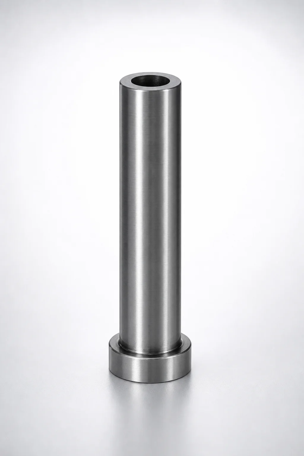
SKD61 Steel Short Straight Ejector Sleeves with Nitride Coating - Head T4
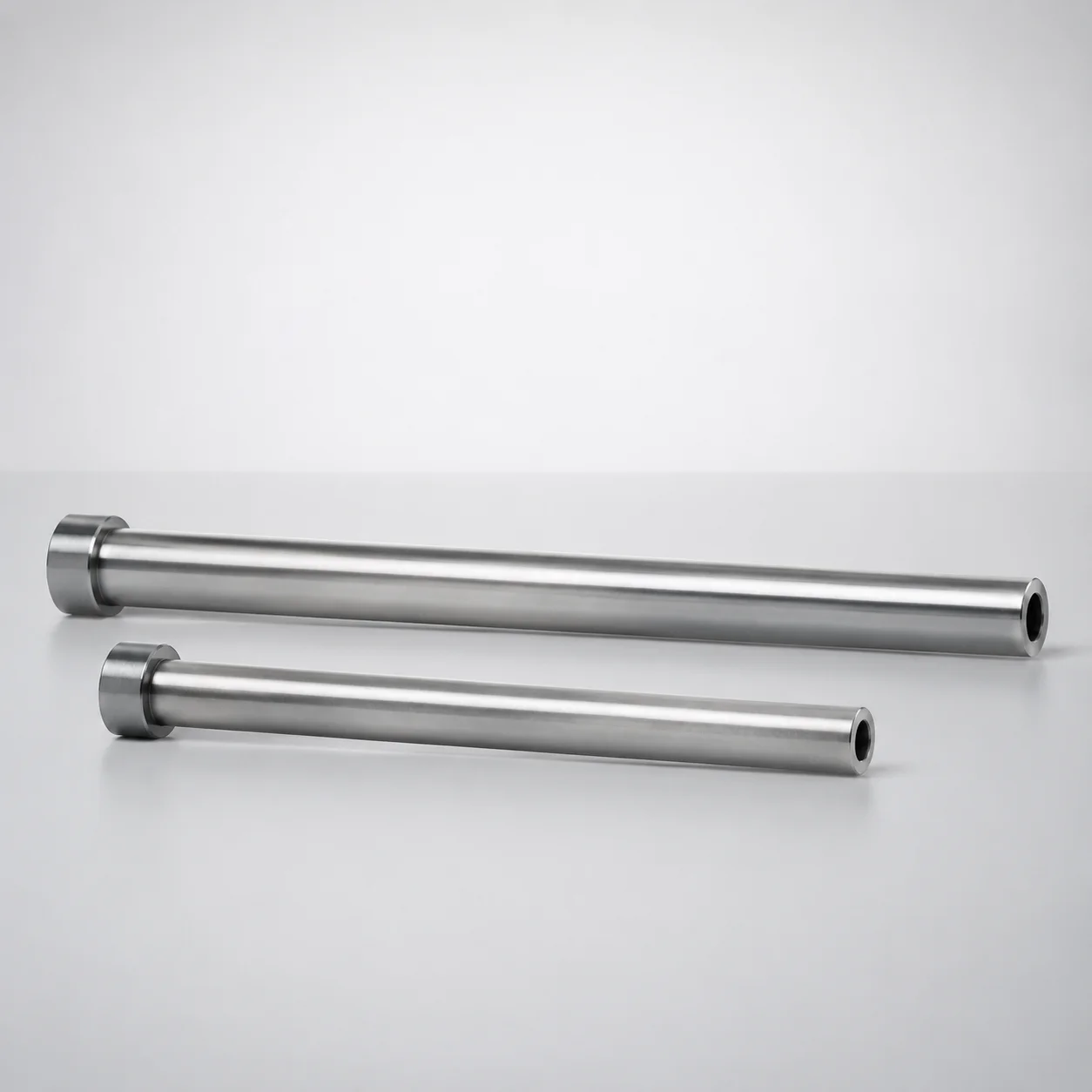
SKD61 Steel Nitrided Straight Ejector Sleeves (ESNV) Head T=4 mm
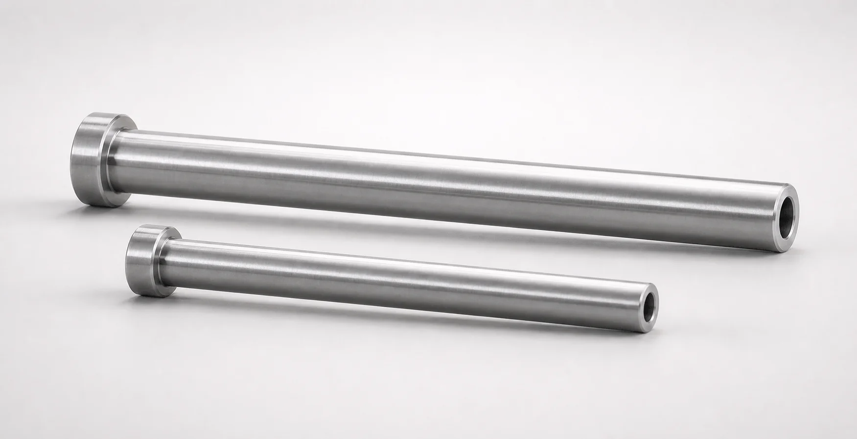
SKD61 Steel Nitrided Straight Ejector Sleeves
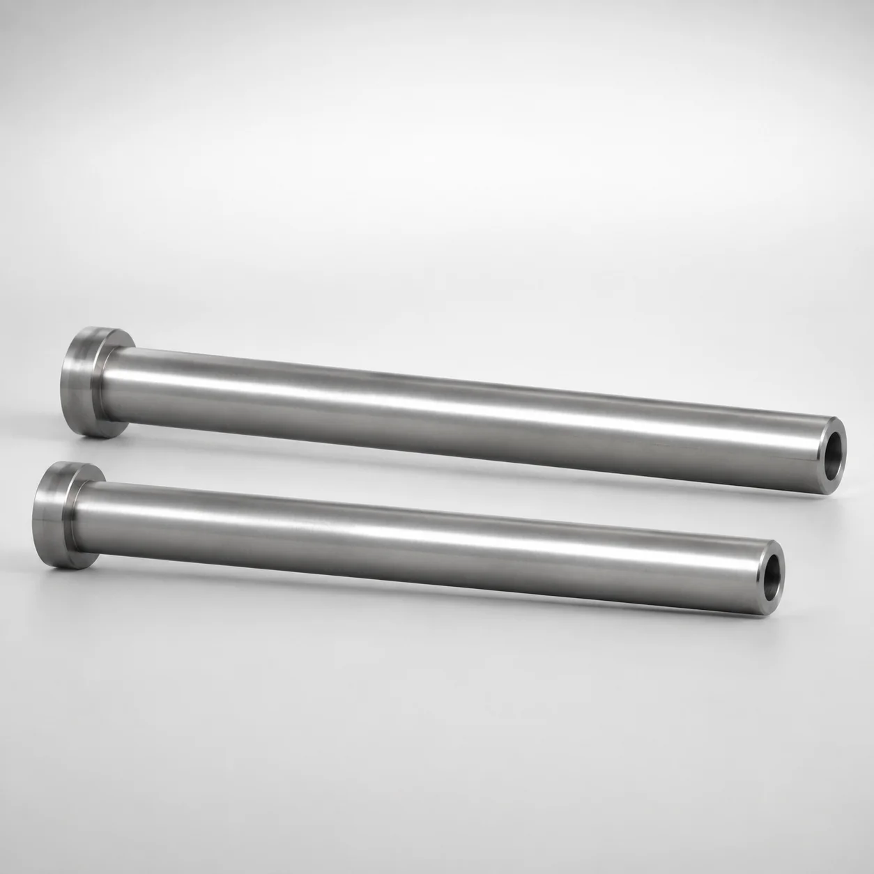
SKD61 Steel Nitrided Straight Ejector Sleeves Head T4
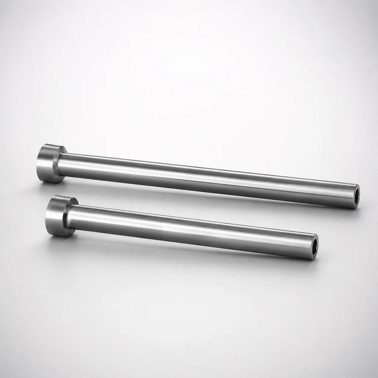
SKD61 Steel Nitrided Straight Ejector Sleeves
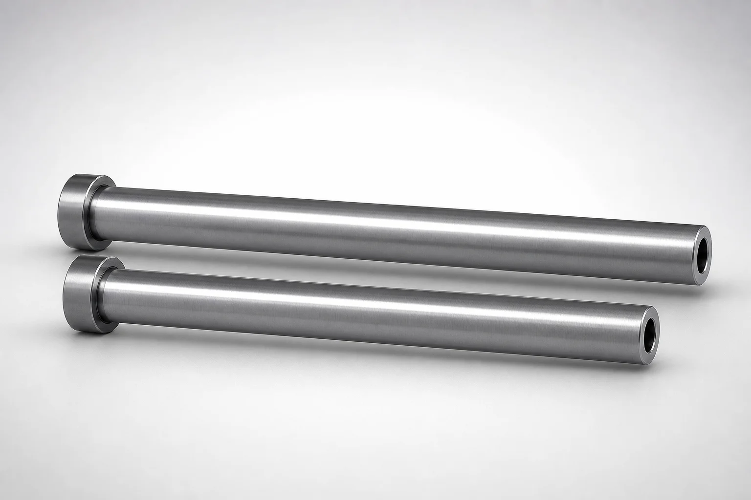
JIS Standard SKD61 Steel Nitrided Straight Ejector Sleeves
Need Custom Specifications?
Our engineering team can help with custom configurations, material selection, and volume pricing.