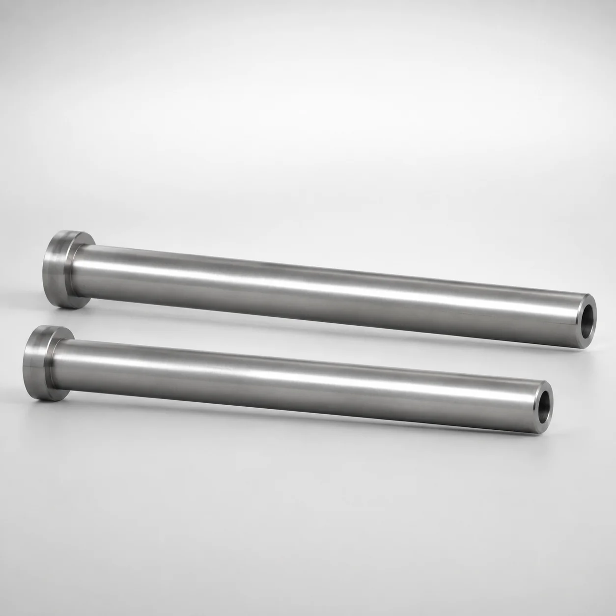
SKD61 Steel Nitrided Straight Ejector Sleeves Head T4
Straight ejector sleeves (SKD61 steel) with nitrided surface treatment are built for wear-resistant, guided ejection in industrial molds. The Head T4 geometry supports stable sleeve alignment and repeatable positioning during production.
- Single sleeve design for consistent straight-line ejection guidance
- Nitrided SKD61 construction delivers strong surface wear resistance
- Controlled bore performance with H7 inner diameter tolerance for fit stability
- Commonly used in injection molding and die casting tooling assemblies
Specifications
20 configurations available
| D/P (Shaft Diameter) (mm) | V (Hole Diameter) (mm) | Shaft diameter designation method | L (L dimension) (mm) | C (Recess diameter) (mm) | S (V hole diameter length) (mm) | type |
|---|---|---|---|---|---|---|
| 4 | 1.5 ~ 2.5 | Shaft diameter selection | 40 ~ 200 | 2 ~ 3 | 20 ~ 50 | - |
| 4.5 | 1.5 ~ 2.5 | Shaft diameter selection | 40 ~ 250 | 2 ~ 3 | 20 ~ 50 | - |
| 5 | 2 ~ 3 | Shaft diameter selection | 40 ~ 250 | 2.5 ~ 3.5 | 20 ~ 50 | - |
| 5.5 | 2 ~ 3.5 | Shaft diameter selection | 40 ~ 250 | 2.5 ~ 4 | 20 ~ 50 | - |
| 6 | 2 ~ 4 | Shaft diameter selection | 40 ~ 300 | 2.5 ~ 4.5 | 20 ~ 50 | - |
| 6.5 | 2 ~ 4.5 | Shaft diameter selection | 40 ~ 300 | 2.5 ~ 5 | 20 ~ 50 | - |
| 7 | 2 ~ 5 | Shaft diameter selection | 40 ~ 300 | 2.5 ~ 5.5 | 20 ~ 50 | - |
| 7.5 | 2 ~ 5.5 | Shaft diameter selection | 40 ~ 300 | 2.5 ~ 6 | 20 ~ 50 | - |
| 8 | 2.5 ~ 6 | Shaft diameter selection | 40 ~ 300 | 3 ~ 6.5 | 20 ~ 50 | - |
| 9 | 2.5 ~ 7 | Shaft diameter selection | 40 ~ 300 | 3 ~ 7.5 | 20 ~ 50 | - |
| 10 | 2.5 ~ 8 | Shaft diameter selection | 40 ~ 300 | 3 ~ 8.5 | 20 ~ 50 | - |
| 3.5 ~ 3.99 | 1.5 ~ 1.9 | Shaft diameter 0.01mm increments | 40 ~ 200 | 2 ~ 2.5 | 20 ~ 40 | - |
| 4.01 ~ 4.99 | 2 ~ 2.5 | Shaft diameter 0.01mm increments | 40 ~ 250 | 2.5 ~ 3 | 20 ~ 50 | - |
| 5.01 ~ 5.49 | 2 ~ 3.4 | Shaft diameter 0.01mm increments | 40 ~ 250 | 2.5 ~ 4 | 20 ~ 50 | - |
| 5.51 ~ 5.99 | 2 ~ 3.9 | Shaft diameter 0.01mm increments | 40 ~ 300 | 2.5 ~ 4.5 | 20 ~ 50 | - |
| 6.01 ~ 6.49 | 2 ~ 4.4 | Shaft diameter 0.01mm increments | 40 ~ 300 | 2.5 ~ 5 | 20 ~ 50 | - |
| 6.51 ~ 6.99 | 2 ~ 4.9 | Shaft diameter 0.01mm increments | 40 ~ 300 | 2.5 ~ 5.5 | 20 ~ 50 | - |
| 7.01 ~ 7.49 | 2 ~ 5.4 | Shaft diameter 0.01mm increments | 40 ~ 300 | 2.5 ~ 6 | 20 ~ 50 | - |
| 7.51 ~ 7.99 | 2.5 ~ 5.9 | Shaft diameter 0.01mm increments | 40 ~ 300 | 3 ~ 6.5 | 20 ~ 50 | - |
| 8.01 ~ 9.99 | 2.5 ~ 7.9 | Shaft diameter 0.01mm increments | 40 ~ 300 | 3 ~ 8.5 | 20 ~ 50 | - |
Product Guide
Application Scenarios+
Used in injection mold tooling as a straight-line ejector sleeve to guide the movement of ejector components and help maintain concentric alignment under repeated cycles.
In automotive connector and housing molds, the nitrided SKD61 base supports stable ejection travel while the Head T4 geometry promotes consistent sleeve positioning, reducing the risk of sticking or side-load wear on mating ejectors.
In appliance and industrial part molding, the H7 inner diameter tolerance variant is suited for controlled fit stability, supporting repeatable clearance over production runs with temperature cycling and abrasive contamination.
For die casting tooling assemblies where guided ejection is critical, the combination of a straight sleeve design and wear-focused surface treatment helps maintain functional guidance and dimensional repeatability.
- Choose this component where guided, straight ejector motion and bore stability are required.
- Head T4 is intended to improve alignment stability during operation.
- H7 bore tolerance supports controlled clearance for reliable ejection guidance.
Material & Process Details+
This variant is made from SKD61 steel and delivered in a nitrided condition. SKD61 is commonly treated as an H13-equivalent hot-work die steel in performance discussions due to its balance of hot strength, toughness, and machinability.
Nitriding creates a hardened surface layer that improves wear resistance and surface durability at the bore, which is critical for guided ejection where friction and sliding contact occur.
- Hardness (typical expectation): nitrided SKD61 generally targets a significantly higher surface hardness than the core; exact HRC is dependent on the nitriding parameters and is set by the manufacturing process.
- Trade-off: nitriding increases surface hardness and wear life, while maintaining a tough core to reduce chipping risk under shock loading.
- Manufacturing: steel is machined to final dimensions, then nitrided to harden the contact surfaces; post-process performance relies on controlled bore/fit.
Compared with un-nitrided SKD61, the nitrided surface offers better sliding wear performance for sleeve-to-ejector guided motion.
Sizing & Selection Guide+
Selection starts by matching the sleeve’s D/P (shaft diameter) to the ejector shaft that runs inside the sleeve. The available shaft diameter range is 3.5 ~ 10 mm, with shaft diameter selection increments of 0.01 mm, enabling close-fit engineering.
Next, match the V (hole diameter) to the interfacing geometry. Available V ranges are 1.5 ~ 2.5 mm, and the S (V hole diameter length) is selectable in 20 ~ 50 mm or 20 ~ 40 mm depending on the configuration.
Choose overall length L based on mold layout and stack-up. Options include 40 ~ 200 mm, 40 ~ 250 mm, and 40 ~ 300 mm.
- Confirm C (recess diameter) in the 2 ~ 3 mm range for the required head/recess fit.
- The inner diameter is specified with H7 tolerance; use an H7 bore assumption when calculating clearance versus the mating shaft’s tolerance.
- Maintain compatibility with the straight-line ejection requirement of your core/cavity design.
Frequently Asked Questions
How do I select the correct D/P (shaft diameter) for this straight ejector sleeve?+
What does the H7 inner diameter tolerance mean for guided ejection fit stability?+
When should I choose a longer L option (40~300 mm) versus a shorter configuration?+
How do V (hole diameter) and S (V hole diameter length) relate to the mold’s interfacing features?+
Why is nitrided SKD61 (Head T4) preferred for guided ejection assemblies?+
Related Products
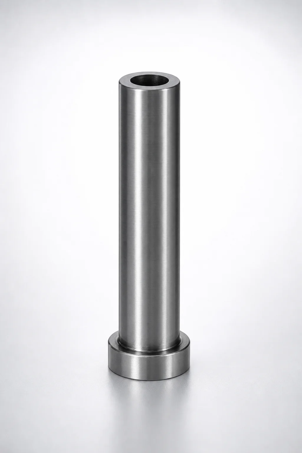
SKD61 Steel Short Straight Ejector Sleeves with Nitride Coating - Head T4
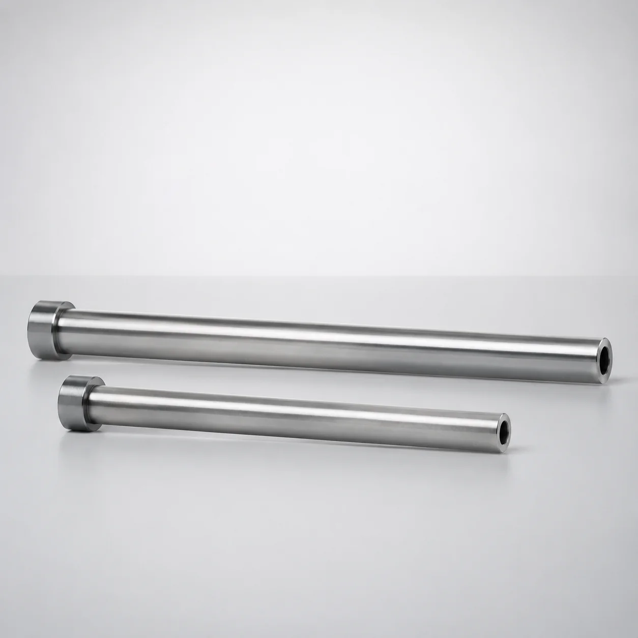
SKD61 Steel Nitrided Straight Ejector Sleeves (ESNV) Head T=4 mm
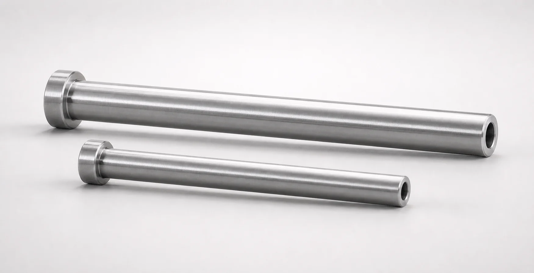
SKD61 Steel Nitrided Straight Ejector Sleeves
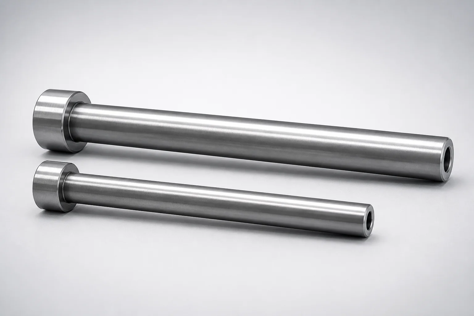
JIS Standard SKD61 Steel Nitrided Straight Ejector Sleeves H7 Bore
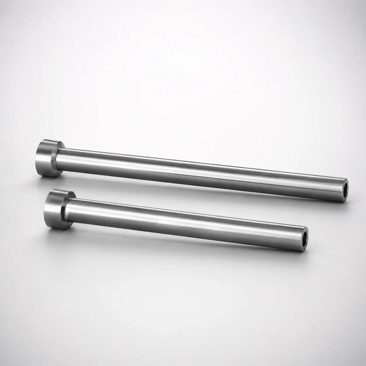
SKD61 Steel Nitrided Straight Ejector Sleeves
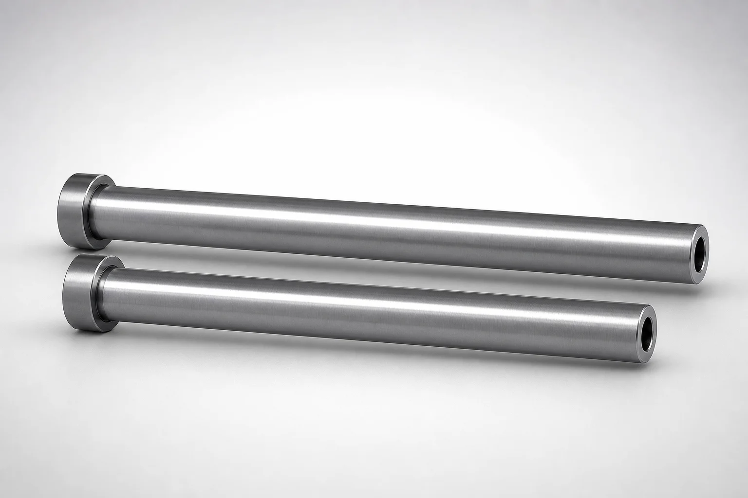
JIS Standard SKD61 Steel Nitrided Straight Ejector Sleeves
Need Custom Specifications?
Our engineering team can help with custom configurations, material selection, and volume pricing.