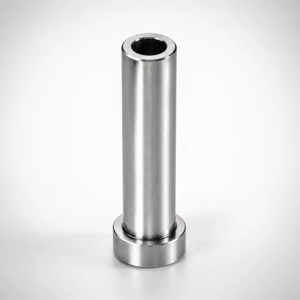
SKH51 Steel Gas Release Round Core Pins
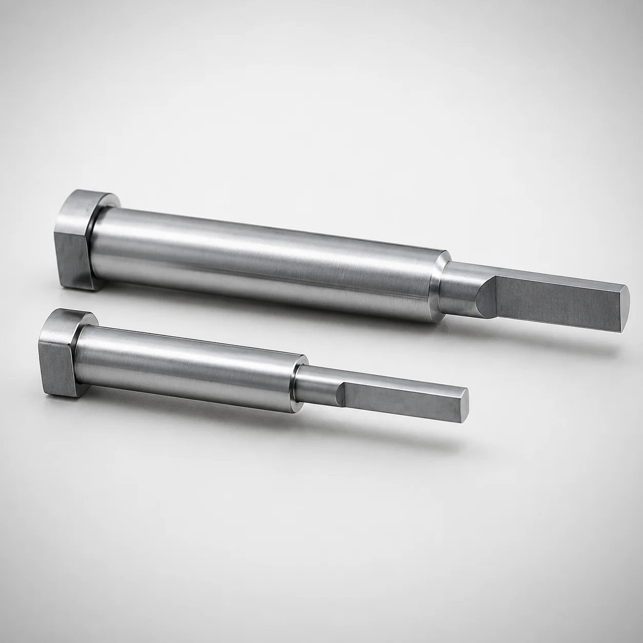
Gas release round core pins (SKH51 steel) are designed to create precise boss shapes in molding applications while improving exhaust efficiency through a dedicated gas vent hole. The pin’s round core profile supports reliable positioning for consistent core performance.
- Built-in gas release hole design to help vent trapped gases during molding
- SKH51 steel with quenched hardening steel for dependable wear resistance
- Supports controlled fit with tight hole tolerance options for stable assembly
- Used in mold core tooling requiring boss formation and controlled exhaust flow
Specifications
134 configurations available
| Hole Tolerance | D/P (Shaft Diameter) (mm) | Hole Shape Type | No. (Nominal diameter) (mm) | A (Hole diameter) (mm) | B (Hole depth) (mm) | C (Chamfering width) (mm) | G (Chamfering width) (mm) | L (L dimension) (mm) | R (Hole end face R) (mm) | V (Hole diameter) (mm) | type |
|---|---|---|---|---|---|---|---|---|---|---|---|
| 0/-0.02 | 3 ~ 3.49 | CG | 3.5 | 1.5 ~ 2 | 0.5 ~ 4 | 0.2 ~ 0.5 | 0.25 ~ 1 | 12.5 ~ 60 | - | 0.8 ~ 1 | - |
| 0/-0.02 | 3.5 ~ 3.99 | CG | 4 | 1.5 ~ 2.5 | 0.5 ~ 4 | 0.2 ~ 0.5 | 0.25 ~ 1 | 12.5 ~ 60 | - | 0.8 ~ 1.5 | - |
| 0/-0.02 | 4 ~ 4.49 | CG | 4.5 | 1.5 ~ 3 | 0.5 ~ 4 | 0.2 ~ 0.5 | 0.25 ~ 1 | 13.5 ~ 60 | - | 0.8 ~ 2 | - |
| 0/-0.02 | 4.5 ~ 4.99 | CG | 5 | 1.5 ~ 3 | 0.5 ~ 4 | 0.2 ~ 0.5 | 0.25 ~ 1 | 13.5 ~ 60 | - | 0.8 ~ 2.5 | - |
| 0/-0.02 | 5 ~ 5.49 | CG | 5.5 | 1.5 ~ 3.5 | 0.5 ~ 4 | 0.2 ~ 0.5 | 0.25 ~ 1 | 14.5 ~ 60 | - | 0.8 ~ 3 | - |
| 0/-0.02 | 5.5 ~ 5.99 | CG | 6 | 1.5 ~ 4 | 0.5 ~ 4 | 0.2 ~ 0.5 | 0.25 ~ 1 | 14.5 ~ 60 | - | 0.8 ~ 3.5 | - |
| 0/-0.02 | 2.5 ~ 2.99 | CS | 3 | 1.5 ~ 1.99 | 0.5 ~ 4 | 0.2 ~ 0.5 | - | 11.5 ~ 60 | - | 0.8 ~ 1.49 | - |
| 0/-0.02 | 3 ~ 3.49 | CS | 3.5 | 1.5 ~ 2 | 0.5 ~ 4 | 0.2 ~ 0.5 | - | 12.5 ~ 60 | - | 0.8 ~ 1.5 | - |
| 0/-0.02 | 3.5 ~ 3.99 | CS | 4 | 1.5 ~ 2.5 | 0.5 ~ 4 | 0.2 ~ 0.5 | - | 12.5 ~ 60 | - | 0.8 ~ 2 | - |
| 0/-0.02 | 4 ~ 4.49 | CS | 4.5 | 1.5 ~ 3 | 0.5 ~ 4 | 0.2 ~ 0.5 | - | 13.5 ~ 60 | - | 0.8 ~ 2.5 | - |
| 0/-0.02 | 4.5 ~ 4.99 | CS | 5 | 1.5 ~ 3 | 0.5 ~ 4 | 0.2 ~ 0.5 | - | 13.5 ~ 60 | - | 0.8 ~ 2.5 | - |
| 0/-0.02 | 5 ~ 5.49 | CS | 5.5 | 1.5 ~ 3.5 | 0.5 ~ 4 | 0.2 ~ 0.5 | - | 14.5 ~ 60 | - | 0.8 ~ 3 | - |
| 0/-0.02 | 5.5 ~ 5.99 | CS | 6 | 1.5 ~ 4 | 0.5 ~ 4 | 0.2 ~ 0.5 | - | 14.5 ~ 60 | - | 0.8 ~ 4 | - |
| 0/-0.02 | 3 ~ 3.49 | RG | 3.5 | 1.5 ~ 2 | 0.5 ~ 4 | - | 0.25 ~ 1 | 12.5 ~ 60 | 0.3 ~ 0.5 | 0.8 ~ 1 | - |
| 0/-0.02 | 3.5 ~ 3.99 | RG | 4 | 1.5 ~ 2.5 | 0.5 ~ 4 | - | 0.25 ~ 1 | 12.5 ~ 60 | 0.3 ~ 0.5 | 0.8 ~ 1.5 | - |
| 0/-0.02 | 4 ~ 4.49 | RG | 4.5 | 1.5 ~ 3 | 0.5 ~ 4 | - | 0.25 ~ 1 | 13.5 ~ 60 | 0.3 ~ 0.5 | 0.8 ~ 2 | - |
| 0/-0.02 | 4.5 ~ 4.99 | RG | 5 | 1.5 ~ 3 | 0.5 ~ 4 | - | 0.25 ~ 1 | 13.5 ~ 60 | 0.3 ~ 0.5 | 0.8 ~ 2.5 | - |
| 0/-0.02 | 5 ~ 5.49 | RG | 5.5 | 1.5 ~ 3.5 | 0.5 ~ 4 | - | 0.25 ~ 1 | 14.5 ~ 60 | 0.3 ~ 0.5 | 0.8 ~ 3 | - |
| 0/-0.02 | 5.5 ~ 5.99 | RG | 6 | 1.5 ~ 4 | 0.5 ~ 4 | - | 0.25 ~ 1 | 14.5 ~ 60 | 0.3 ~ 0.5 | 0.8 ~ 3.5 | - |
| 0/-0.02 | 3 ~ 3.49 | SG | 3.5 | 1.5 ~ 2 | 0.5 ~ 4 | - | 0.25 ~ 1 | 12.5 ~ 60 | - | 0.8 ~ 1 | - |
| 0/-0.02 | 3.5 ~ 3.99 | SG | 4 | 1.5 ~ 2.5 | 0.5 ~ 4 | - | 0.25 ~ 1 | 12.5 ~ 60 | - | 0.8 ~ 1.5 | - |
| 0/-0.02 | 4 ~ 4.49 | SG | 4.5 | 1.5 ~ 3 | 0.5 ~ 4 | - | 0.25 ~ 1 | 13.5 ~ 60 | - | 0.8 ~ 2 | - |
| 0/-0.02 | 4.5 ~ 4.99 | SG | 5 | 1.5 ~ 3 | 0.5 ~ 4 | - | 0.25 ~ 1 | 13.5 ~ 60 | - | 0.8 ~ 2.5 | - |
| 0/-0.02 | 5 ~ 5.49 | SG | 5.5 | 1.5 ~ 3.5 | 0.5 ~ 4 | - | 0.25 ~ 1 | 14.5 ~ 60 | - | 0.8 ~ 3 | - |
| 0/-0.02 | 5.5 ~ 5.99 | SG | 6 | 1.5 ~ 4 | 0.5 ~ 4 | - | 0.25 ~ 1 | 14.5 ~ 60 | - | 0.8 ~ 3.5 | - |
| 0/-0.02 | 2.5 ~ 2.99 | SS | 3 | 1.5 ~ 2.49 | 0.5 ~ 4 | - | - | 10 ~ 60 | - | 0.8 ~ 1 | - |
| 0/-0.02 | 3 ~ 3.49 | SS | 3.5 | 1.5 ~ 2.49 | 0.5 ~ 4 | - | - | 12.5 ~ 60 | - | 0.8 ~ 1.5 | - |
| 0/-0.02 | 3.5 ~ 3.99 | SS | 4 | 1.5 ~ 2.5 | 0.5 ~ 4 | - | - | 12.5 ~ 60 | - | 0.8 ~ 2 | - |
| 0/-0.02 | 4 ~ 4.49 | SS | 4.5 | 1.5 ~ 3 | 0.5 ~ 4 | - | - | 13.5 ~ 60 | - | 0.8 ~ 2.5 | - |
| 0/-0.02 | 4.5 ~ 4.99 | SS | 5 | 1.5 ~ 3 | 0.5 ~ 4 | - | - | 13.5 ~ 60 | - | 0.8 ~ 2.5 | - |
| 0/-0.02 | 5 ~ 5.49 | SS | 5.5 | 1.5 ~ 3.99 | 0.5 ~ 4 | - | - | 14.5 ~ 60 | - | 0.8 ~ 3 | - |
| 0/-0.02 | 5.5 ~ 5.99 | SS | 6 | 1.5 ~ 4.49 | 0.5 ~ 4 | - | - | 14.5 ~ 60 | - | 0.8 ~ 4 | - |
| 0/-0.02 | 3 | CG | - | 1.5 ~ 2 | 0.5 ~ 4 | 0.2 ~ 0.5 | 0.25 ~ 1 | 11.5 ~ 60 | - | 0.8 ~ 1 | - |
| 0/-0.02 | 3.5 | CG | - | 1.5 ~ 2.5 | 0.5 ~ 4 | 0.2 ~ 0.5 | 0.25 ~ 1 | 12.5 ~ 60 | - | 0.8 ~ 1.5 | - |
| 0/-0.02 | 4 | CG | - | 1.5 ~ 3 | 0.5 ~ 4 | 0.2 ~ 0.5 | 0.25 ~ 1 | 12.5 ~ 60 | - | 0.8 ~ 2 | - |
| 0/-0.02 | 4.5 | CG | - | 1.5 ~ 3.5 | 0.5 ~ 4 | 0.2 ~ 0.5 | 0.25 ~ 1 | 13.5 ~ 60 | - | 0.8 ~ 2.5 | - |
| 0/-0.02 | 5 | CG | - | 1.5 ~ 3.5 | 0.5 ~ 4 | 0.2 ~ 0.5 | 0.25 ~ 1 | 13.5 ~ 60 | - | 0.8 ~ 3 | - |
| 0/-0.02 | 5.5 | CG | - | 1.5 ~ 4 | 0.5 ~ 4 | 0.2 ~ 0.5 | 0.25 ~ 1 | 14.5 ~ 60 | - | 0.8 ~ 3.5 | - |
| 0/-0.02 | 6 | CG | - | 1.5 ~ 4.5 | 0.5 ~ 4 | 0.2 ~ 0.5 | 0.25 ~ 1 | 14.5 ~ 60 | - | 0.8 ~ 4 | - |
| 0/-0.02 | 3 | CS | - | 1.5 ~ 2 | 0.5 ~ 4 | 0.2 ~ 0.5 | - | 11.5 ~ 60 | - | 0.8 ~ 1.5 | - |
| 0/-0.02 | 3.5 | CS | - | 1.5 ~ 2.5 | 0.5 ~ 4 | 0.2 ~ 0.5 | - | 12.5 ~ 60 | - | 0.8 ~ 2 | - |
| 0/-0.02 | 4 | CS | - | 1.5 ~ 3 | 0.5 ~ 4 | 0.2 ~ 0.5 | - | 12.5 ~ 60 | - | 0.8 ~ 2.5 | - |
| 0/-0.02 | 4.5 | CS | - | 1.5 ~ 3.5 | 0.5 ~ 4 | 0.2 ~ 0.5 | - | 13.5 ~ 60 | - | 0.8 ~ 3 | - |
| 0/-0.02 | 5 | CS | - | 1.5 ~ 3.5 | 0.5 ~ 4 | 0.2 ~ 0.5 | - | 13.5 ~ 60 | - | 0.8 ~ 3.5 | - |
| 0/-0.02 | 5.5 | CS | - | 1.5 ~ 4 | 0.5 ~ 4 | 0.2 ~ 0.5 | - | 14.5 ~ 60 | - | 0.8 ~ 4 | - |
| 0/-0.02 | 6 | CS | - | 1.5 ~ 4.5 | 0.5 ~ 4 | 0.2 ~ 0.5 | - | 14.5 ~ 60 | - | 0.8 ~ 4.5 | - |
| 0/-0.02 | 3 | RG | - | 1.5 ~ 2 | 0.5 ~ 4 | - | 0.25 ~ 1 | 11.5 ~ 60 | 0.3 ~ 0.5 | 0.8 ~ 1 | - |
| 0/-0.02 | 3.5 | RG | - | 1.5 ~ 2.5 | 0.5 ~ 4 | - | 0.25 ~ 1 | 12.5 ~ 60 | 0.3 ~ 0.5 | 0.8 ~ 1.5 | - |
| 0/-0.02 | 4 | RG | - | 1.5 ~ 3 | 0.5 ~ 4 | - | 0.25 ~ 1 | 12.5 ~ 60 | 0.3 ~ 0.5 | 0.8 ~ 2 | - |
| 0/-0.02 | 4.5 | RG | - | 1.5 ~ 3.5 | 0.5 ~ 4 | - | 0.25 ~ 1 | 13.5 ~ 60 | 0.3 ~ 0.5 | 0.8 ~ 2.5 | - |
Product Guide
Application Scenarios+
These gas release round core pins are used in injection mold tooling when the cavity includes a boss or raised feature that also requires reliable venting. The built-in gas vent hole design supports faster exhaust of trapped air and volatiles, helping reduce gas-related defects while maintaining stable core placement.
- Automotive connector and housing molds: ideal for small, repeatable bosses where consistent venting helps prevent short shots and surface burn marks around the boss.
- Consumer electronics enclosures: suited for thin-wall parts with localized features; the round core profile supports controlled positioning while the vent hole improves mold breathing.
- General-purpose precision core tooling: the multiple hole shape types (CG/CS/RG/SG/SS) allow engineers to match exhaust geometry to gate/flow patterns for steady support.
For these applications, the SKH51 steel variant provides wear resistance needed for repeated cycling, especially where vented cores experience friction during assembly and demolding.
Material & Process Details+
SKH51 steel is a high-performance tool steel (commonly compared to AISI M2 in wear/cutting tool applications). It is typically supplied in a heat-treated condition with quenched and tempered hardening to balance hardness and toughness for core pin service.
- Hardness: designed for high wear resistance; the quenched & tempered hardening state provides stable hardness under intermittent loading.
- Wear resistance vs. toughness: as hardness increases, the component generally becomes less tolerant of severe shock. For core pins that see steady demolding loads and vent-related friction, this trade-off is beneficial.
Compared with softer structural tool steels, SKH51’s higher hardness supports longer life in sliding and repetitive core operations. Compared with more specialized nitriding-focused grades, SKH51’s through-hardening condition can be advantageous when you need reliable hardness without relying solely on surface-only treatments.
Sizing & Selection Guide+
Select the pin geometry by matching the boss/core feature in the mold cavity to the pin’s nominal and functional dimensions. Start with D/P (shaft diameter) in the range 2.5–6 mm and choose the No. (nominal diameter) from 3–6 mm to ensure the pin fits the guide/boss bore system used by your core tooling.
- Hole diameter (A): fixed at 1.5 mm for the gas vent function.
- Hole depth (B): fixed at 0.5–4 mm depending on the selected pin length variant.
- Chamfer: fixed C = 0.2–0.5 mm and G = 0.25–1 mm—confirm these match the vent-hole entry/relief requirements.
- Length (L): variable across options such as 10–60 mm, 11.5–60 mm, 12.5–60 mm, 13.5–60 mm, or 14.5–60 mm.
For fit, use the available hole tolerance options: 0/-0.02 or 0/-0.01 to control clearance and prevent wobble during support. If you must align exhaust timing precisely, also select the hole shape type (CG/CS/RG/SG/SS) appropriate to your vent path geometry.
Frequently Asked Questions
Which hole tolerance should I use for stable assembly of these gas release round core pins?+
Choose the hole tolerance option based on the clearance you need in your core support bore: 0/-0.02 for a tighter limit or 0/-0.01 for a slightly less restrictive negative tolerance. Both options are designed to support a controlled fit so the core remains stable during cycling. Verify the selected tolerance matches your guide/core housing size program.
How do I match the pin length (L) and hole depth (B) to my boss insert core depth?+
Use L to match the required engagement length into the mold tooling, with available ranges such as 10–60, 11.5–60, 12.5–60, 13.5–60, or 14.5–60 mm. Then confirm the built-in vent geometry through B (hole depth), which is fixed in the range 0.5–4 mm. Keep the vent hole depth consistent with how far gases must travel before exit from the boss region.
What are the fixed vent-hole dimensions, and can I adjust the vent-hole diameter (A) or end-face radius (R)?+
The vent-hole diameter A is fixed at 1.5 mm, and the hole-end face radius R is fixed in the range 0.3–0.5 mm. The chamfering is also fixed with C = 0.2–0.5 mm and G = 0.25–1 mm. This means gas vent diameter and key corner relief features are not independently adjustable beyond selecting the corresponding pin variant.
How do D/P (shaft diameter) and No. (nominal diameter) relate when selecting the right pin for boss cores?+
Select D/P first to match the core pin shaft requirement in your assembly: 2.5–6 mm. Then choose the No. (nominal diameter) from 3–6 mm to align with the nominal feature size for locating and support within the core tooling. Ensuring both ranges align with your housing and guide design helps prevent misalignment that could compromise boss shape accuracy.
Which vent-hole shape types (CG/CS/RG/SG/SS) should I consider for different exhaust paths?+
This series supports multiple hole shape types: CG, CS, RG, SG, and SS. If your exhaust path needs different vent entry geometry or internal shaping, pick the option that best matches your mold’s vent channel layout around the boss. Use the available vent-hole tolerance and length settings to maintain stable support while changing vent geometry.
Related Products
Need Custom Specifications?
Our engineering team can help with custom configurations, material selection, and volume pricing.