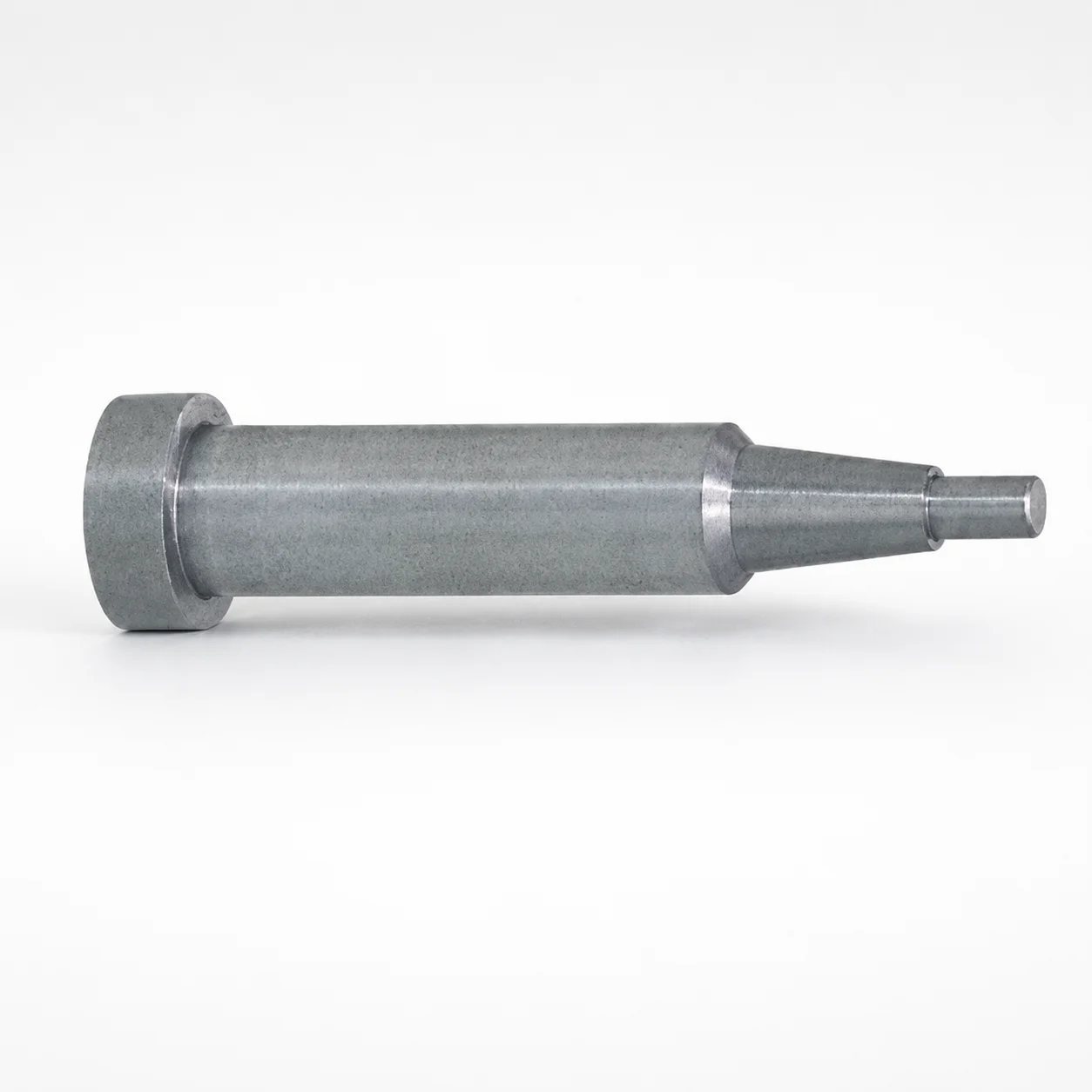
JIS Standard Hardened Steel Inlay Core Pins Flat-Sided
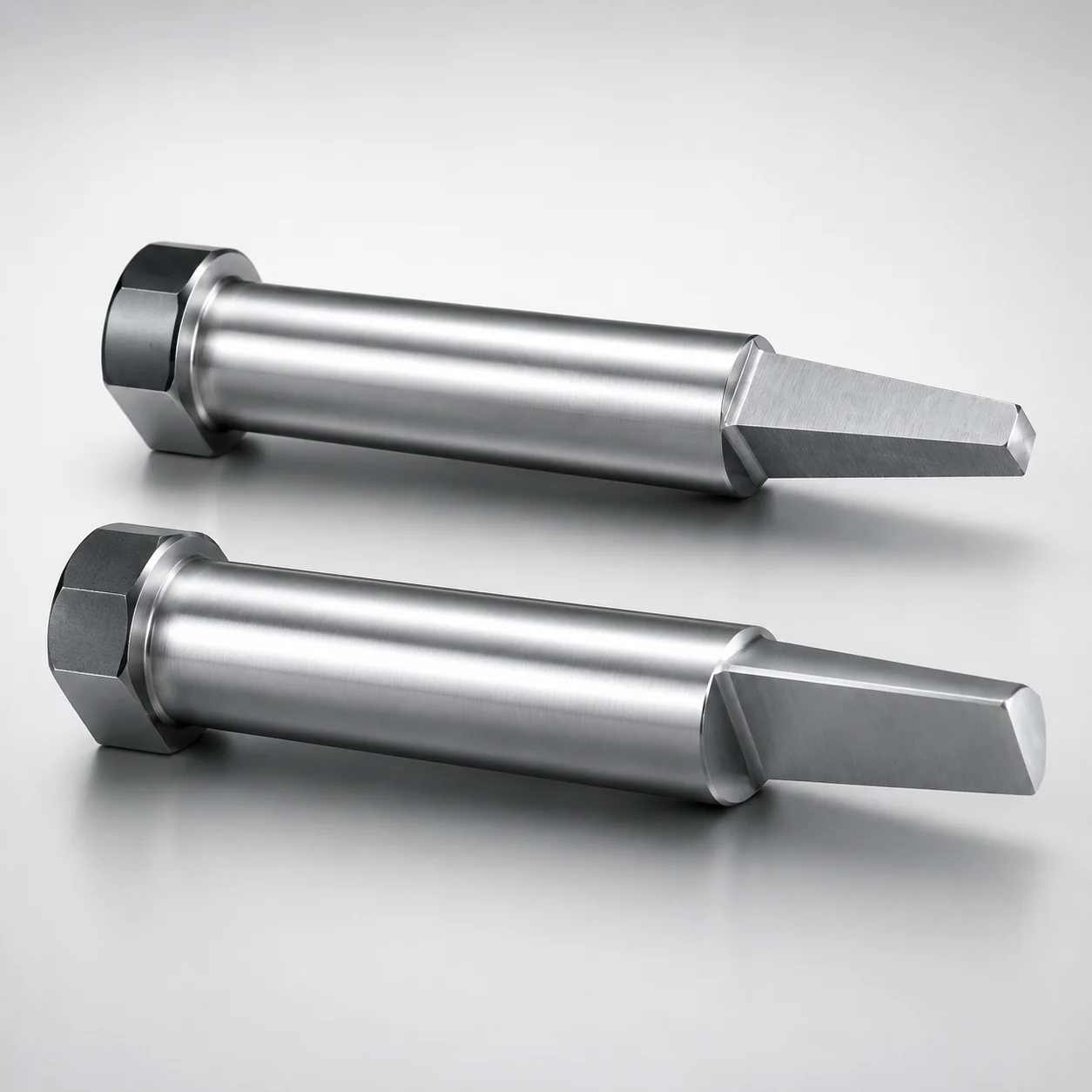
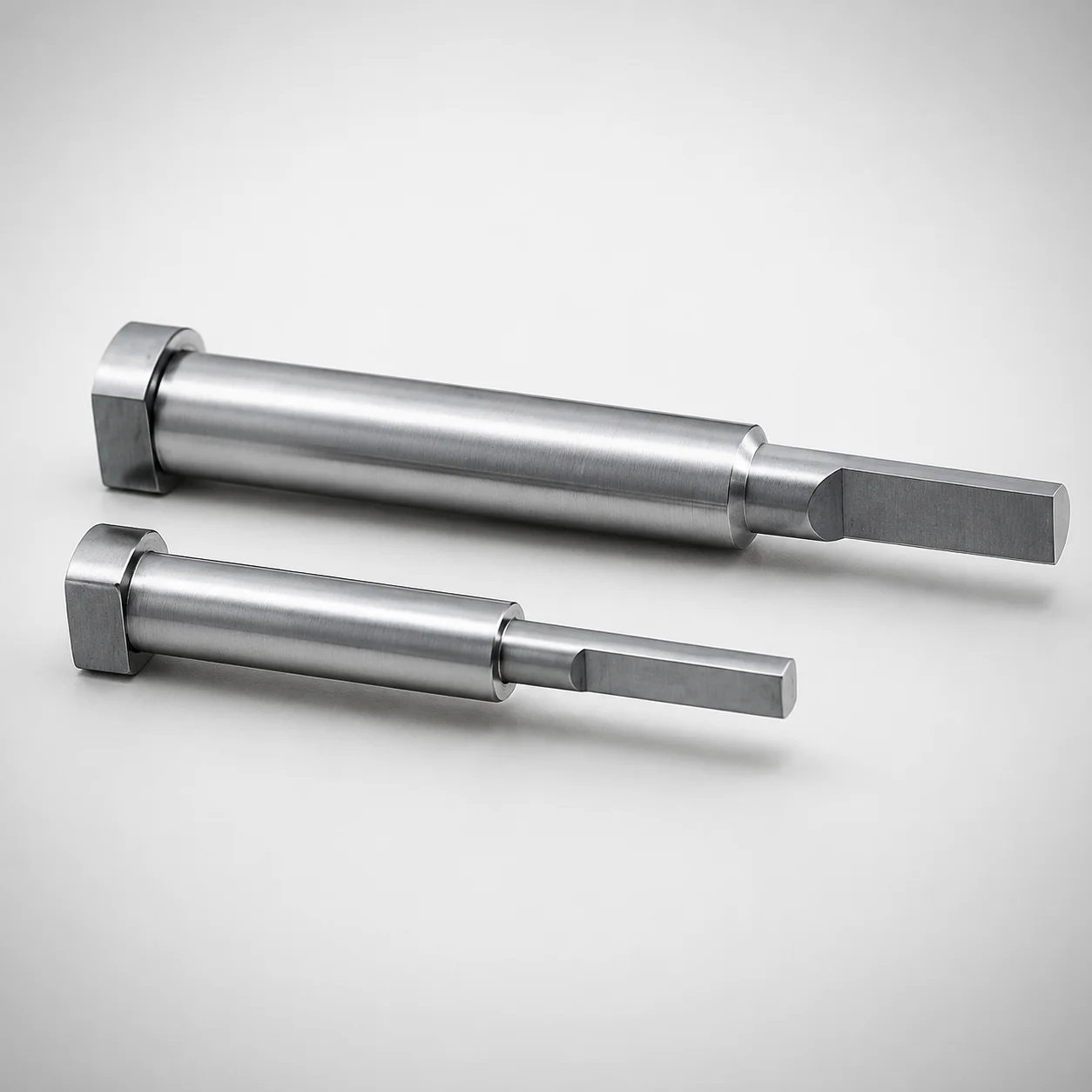
Inlay Core Pins flat-sided are built for stable alignment in precision molds and assembly systems. The flat-sided anti-rotation head helps maintain repeatable positioning during repeated ejection cycles.
- Flat-sided anti-rotation head improves positional stability for consistent assembly accuracy
- Durable hardened steel construction supports long service life and reduced wear on mating parts
- Supports tight shaft diameter control with 0/-0.005 to -0.01/-0.02 selectable tolerance references
- Suitable for tooling, fixtures, and inlay core applications requiring reliable core location
Specifications
340 configurations available
| Material | Shaft Diameter Tolerance | D/P (Shaft Diameter) (mm) | Tip Step Shape | L Dimension Tolerance | Tip Gradient Tolerance | No. (Nominal diameter) (mm) | A (Step shape diameter) (mm) | B (Inlay section length) (mm) | C (Tip part) (mm) | F (Bearing bore length) (mm) | L (L dimension) (mm) | R (Tip part) (mm) | S (Inlay section diameter) (mm) | V (Tip part) (mm) | type |
|---|---|---|---|---|---|---|---|---|---|---|---|---|---|---|---|
| SKD61 | -0.01/-0.02 | 1 ~ 1.49 | A | +0.02/0 | ±0.015 | 1.5 | - | 0.7 ~ 12.3 | - | 10 ~ 98.5 | 12 ~ 100 | - | 0.5 ~ 1.47 | 0.51 ~ 1.48 | - |
| SKD61 | -0.01/-0.02 | 1.5 ~ 1.99 | A | +0.02/0 | ±0.015 | 2 | - | 0.7 ~ 14.8 | - | 10 ~ 98.5 | 12 ~ 100 | - | 0.7 ~ 1.97 | 0.71 ~ 1.98 | - |
| SKD61 | -0.01/-0.02 | 2 ~ 2.49 | A | +0.02/0 | ±0.015 | 2.5 | - | 0.1 ~ 12.3 | - | 10 ~ 97.5 | 12 ~ 100 | - | 0.7 ~ 2.47 | 0.71 ~ 2.48 | - |
| SKD61 | -0.01/-0.02 | 2.5 ~ 2.99 | A | +0.02/0 | ±0.015 | 3 | - | 0.1 ~ 14.8 | - | 10 ~ 97.5 | 12 ~ 100 | - | 1 ~ 2.97 | 1.01 ~ 2.98 | - |
| SKD61 | -0.01/-0.02 | 3 ~ 3.49 | A | +0.02/0 | ±0.015 | 3.5 | - | 0.1 ~ 17.3 | - | 10 ~ 114.5 | 12 ~ 119.3 | - | 1 ~ 3.47 | 1.01 ~ 3.48 | - |
| SKD61 | -0.01/-0.02 | 3.5 ~ 3.99 | A | +0.02/0 | ±0.015 | 4 | - | 0.1 ~ 19.8 | - | 10 ~ 115.95 | 12 ~ 119.3 | - | 1 ~ 3.97 | 1.01 ~ 3.98 | - |
| SKD61 | -0.01/-0.02 | 4 ~ 4.49 | A | +0.02/0 | ±0.015 | 4.5 | - | 0.1 ~ 22.3 | - | 10 ~ 115.95 | 12 ~ 119.3 | - | 1.5 ~ 4.47 | 1.01 ~ 4.48 | - |
| SKD61 | -0.01/-0.02 | 4.5 ~ 4.99 | A | +0.02/0 | ±0.015 | 5 | - | 0.1 ~ 24.8 | - | 10 ~ 115.95 | 12 ~ 119.3 | - | 1.5 ~ 4.97 | 1.51 ~ 4.98 | - |
| SKD61 | -0.01/-0.02 | 5 ~ 5.49 | A | +0.02/0 | ±0.015 | 5.5 | - | 0.1 ~ 27.3 | - | 10 ~ 115.95 | 12 ~ 119.3 | - | 1.5 ~ 5.47 | 1.51 ~ 5.48 | - |
| SKD61 | -0.01/-0.02 | 5.5 ~ 5.99 | A | +0.02/0 | ±0.015 | 6 | - | 0.1 ~ 29.8 | - | 10 ~ 115.95 | 12 ~ 119.3 | - | 2 ~ 5.97 | 2.01 ~ 5.98 | - |
| SKD61 | -0.01/-0.02 | 6 ~ 6.49 | A | +0.02/0 | ±0.015 | 6.5 | - | 0.1 ~ 32.3 | - | 10 ~ 115.95 | 12 ~ 119.3 | - | 2 ~ 6.47 | 2.01 ~ 6.48 | - |
| SKD61 | -0.01/-0.02 | 6.5 ~ 6.99 | A | +0.02/0 | ±0.015 | 7 | - | 0.1 ~ 34.8 | - | 10 ~ 115.95 | 12 ~ 119.3 | - | 2 ~ 6.97 | 2.01 ~ 6.98 | - |
| SKD61 | -0.01/-0.02 | 7 ~ 7.99 | A | +0.02/0 | ±0.015 | 8 | - | 0.1 ~ 38.8 | - | 10 ~ 115.95 | 12 ~ 119.3 | - | 2 ~ 7.97 | 2.01 ~ 7.98 | - |
| SKD61 | -0.01/-0.02 | 8 ~ 9.99 | A | +0.02/0 | ±0.015 | 10 | - | 0.1 ~ 49.8 | - | 10 ~ 115.95 | 12 ~ 119.3 | - | 2 ~ 9.97 | 2.01 ~ 9.98 | - |
| SKD61 | -0.01/-0.02 | 10 ~ 12.99 | A | +0.02/0 | ±0.015 | 13 | - | 0.7 ~ 64.8 | - | 10 ~ 119.9 | 12 ~ 120 | - | 2.5 ~ 12.97 | 2.51 ~ 12.98 | - |
| SKD61 | -0.01/-0.02 | 13 ~ 15.99 | A | +0.02/0 | ±0.015 | 16 | - | 0.7 ~ 79.8 | - | 10 ~ 119.5 | 12 ~ 120 | - | 2.5 ~ 15.97 | 2.51 ~ 15.98 | - |
| SKD61 | -0.01/-0.02 | 16 ~ 19.98 | A | +0.02/0 | ±0.015 | 20 | - | 0.7 ~ 91.5 | - | 28 ~ 110 | 30 ~ 119.3 | - | 5 ~ 19.98 | 5 ~ 19.99 | - |
| SKD61 | -0.01/-0.02 | 1 ~ 1.49 | B | +0.02/0 | ±0.015 | 1.5 | 0.51 ~ 1.48 | 0.7 ~ 12.3 | - | 10 ~ 98.5 | 12 ~ 100 | - | 0.5 ~ 1.47 | 0.51 ~ 1.48 | - |
| SKD61 | -0.01/-0.02 | 1.5 ~ 1.99 | B | +0.02/0 | ±0.015 | 2 | 0.71 ~ 1.98 | 0.7 ~ 14.8 | - | 10 ~ 96 | 12 ~ 100 | - | 0.7 ~ 1.97 | 0.71 ~ 1.98 | - |
| SKD61 | -0.01/-0.02 | 2 ~ 2.49 | B | +0.02/0 | ±0.015 | 2.5 | 0.71 ~ 2.48 | 0.1 ~ 12.3 | - | 10 ~ 98.5 | 12 ~ 100 | - | 0.7 ~ 2.47 | 0.71 ~ 2.48 | - |
| SKD61 | -0.01/-0.02 | 2.5 ~ 2.99 | B | +0.02/0 | ±0.015 | 3 | 1.01 ~ 2.98 | 0.1 ~ 14.8 | - | 10 ~ 98.5 | 12 ~ 100 | - | 1 ~ 2.97 | 1.01 ~ 2.98 | - |
| SKD61 | -0.01/-0.02 | 3 ~ 3.49 | B | +0.02/0 | ±0.015 | 3.5 | 1.01 ~ 3.48 | 0.1 ~ 17.3 | - | 10 ~ 114.9 | 12 ~ 119.3 | - | 1 ~ 3.47 | 1.01 ~ 3.48 | - |
| SKD61 | -0.01/-0.02 | 3.5 ~ 3.99 | B | +0.02/0 | ±0.015 | 4 | 1.01 ~ 3.98 | 0.1 ~ 19.8 | - | 10 ~ 114.9 | 12 ~ 119.3 | - | 1 ~ 3.97 | 1.01 ~ 3.98 | - |
| SKD61 | -0.01/-0.02 | 4 ~ 4.49 | B | +0.02/0 | ±0.015 | 4.5 | 1.51 ~ 4.48 | 0.1 ~ 22.3 | - | 10 ~ 115.95 | 12 ~ 119.3 | - | 1.5 ~ 4.47 | 1.51 ~ 4.48 | - |
| SKD61 | -0.01/-0.02 | 4.5 ~ 4.99 | B | +0.02/0 | ±0.015 | 5 | 1.51 ~ 4.98 | 0.1 ~ 24.8 | - | 10 ~ 115.95 | 12 ~ 119.3 | - | 1.5 ~ 4.97 | 1.51 ~ 4.98 | - |
| SKD61 | -0.01/-0.02 | 5 ~ 5.49 | B | +0.02/0 | ±0.015 | 5.5 | 1.51 ~ 5.48 | 0.1 ~ 27.3 | - | 10 ~ 115.95 | 12 ~ 119.3 | - | 1.5 ~ 5.47 | 1.51 ~ 5.48 | - |
| SKD61 | -0.01/-0.02 | 5.5 ~ 5.99 | B | +0.02/0 | ±0.015 | 6 | 2.01 ~ 5.98 | 0.1 ~ 29.8 | - | 10 ~ 115.95 | 12 ~ 119.3 | - | 2 ~ 5.97 | 2.01 ~ 5.98 | - |
| SKD61 | -0.01/-0.02 | 6 ~ 6.49 | B | +0.02/0 | ±0.015 | 6.5 | 2.01 ~ 6.48 | 0.1 ~ 32.3 | - | 10 ~ 115.95 | 12 ~ 119.3 | - | 2 ~ 6.47 | 2.01 ~ 6.48 | - |
| SKD61 | -0.01/-0.02 | 6.5 ~ 6.99 | B | +0.02/0 | ±0.015 | 7 | 2.01 ~ 6.98 | 0.1 ~ 34.8 | - | 10 ~ 115.95 | 12 ~ 119.3 | - | 2 ~ 6.97 | 2.01 ~ 6.98 | - |
| SKD61 | -0.01/-0.02 | 7 ~ 7.99 | B | +0.02/0 | ±0.015 | 8 | 2.01 ~ 7.98 | 0.1 ~ 38.8 | - | 10 ~ 115.95 | 12 ~ 119.3 | - | 2 ~ 7.97 | 2.01 ~ 7.98 | - |
| SKD61 | -0.01/-0.02 | 8 ~ 9.99 | B | +0.02/0 | ±0.015 | 10 | 2.01 ~ 9.98 | 0.1 ~ 49.8 | - | 10 ~ 114.95 | 12 ~ 119.3 | - | 2 ~ 9.97 | 2.01 ~ 9.98 | - |
| SKD61 | -0.01/-0.02 | 10 ~ 12.99 | B | +0.02/0 | ±0.015 | 13 | 2.51 ~ 12.98 | 0.7 ~ 64.8 | - | 10 ~ 119.5 | 12 ~ 120 | - | 2.5 ~ 12.97 | 2.51 ~ 12.98 | - |
| SKD61 | -0.01/-0.02 | 13 ~ 15.99 | B | +0.02/0 | ±0.015 | 16 | 2.51 ~ 15.98 | 0.7 ~ 79.8 | - | 10 ~ 119.5 | 12 ~ 120 | - | 2.5 ~ 15.97 | 2.51 ~ 15.98 | - |
| SKD61 | -0.01/-0.02 | 16 ~ 19.99 | B | +0.02/0 | ±0.015 | 20 | 5 ~ 19.98 | 0.7 ~ 91.3 | - | 28 ~ 110 | 30 ~ 119.3 | - | 5 ~ 19.98 | 5 ~ 19.99 | - |
| SKD61 | -0.01/-0.02 | 1 ~ 1.49 | C | +0.02/0 | ±0.015 | 1.5 | 0.51 ~ 1.48 | 0.7 ~ 12.3 | - | 10 ~ 98.5 | 12 ~ 100 | - | 0.5 ~ 1.47 | 0.51 ~ 1.48 | - |
| SKD61 | -0.01/-0.02 | 1.5 ~ 1.99 | C | +0.02/0 | ±0.015 | 2 | 0.71 ~ 1.98 | 0.7 ~ 14.8 | - | 10 ~ 98.5 | 12 ~ 100 | - | 0.7 ~ 1.97 | 0.71 ~ 1.98 | - |
| SKD61 | -0.01/-0.02 | 2 ~ 2.49 | C | +0.02/0 | ±0.015 | 2.5 | 0.71 ~ 2.48 | 0.1 ~ 12.3 | - | 10 ~ 98.5 | 12 ~ 100 | - | 0.7 ~ 2.47 | 0.71 ~ 2.48 | - |
| SKD61 | -0.01/-0.02 | 2.5 ~ 2.99 | C | +0.02/0 | ±0.015 | 3 | 1.01 ~ 2.98 | 0.1 ~ 14.8 | - | 10 ~ 98.5 | 12 ~ 100 | - | 1 ~ 2.97 | 1.01 ~ 2.98 | - |
| SKD61 | -0.01/-0.02 | 3 ~ 3.49 | C | +0.02/0 | ±0.015 | 3.5 | 1.01 ~ 3.48 | 0.1 ~ 17.3 | - | 10 ~ 115.95 | 12 ~ 119.3 | - | 1 ~ 3.47 | 1.01 ~ 3.48 | - |
| SKD61 | -0.01/-0.02 | 3.5 ~ 3.99 | C | +0.02/0 | ±0.015 | 4 | 1.01 ~ 3.98 | 0.1 ~ 19.8 | - | 10 ~ 115.95 | 12 ~ 119.3 | - | 1 ~ 3.97 | 1.01 ~ 3.98 | - |
| SKD61 | -0.01/-0.02 | 4 ~ 4.49 | C | +0.02/0 | ±0.015 | 4.5 | 1.51 ~ 4.48 | 0.1 ~ 22.3 | - | 10 ~ 115.95 | 12 ~ 119.3 | - | 1.5 ~ 4.47 | 1.51 ~ 4.48 | - |
| SKD61 | -0.01/-0.02 | 4.5 ~ 4.99 | C | +0.02/0 | ±0.015 | 5 | 1.51 ~ 4.98 | 0.1 ~ 24.8 | - | 10 ~ 115.95 | 12 ~ 119.3 | - | 1.5 ~ 4.97 | 1.51 ~ 4.98 | - |
| SKD61 | -0.01/-0.02 | 5 ~ 5.49 | C | +0.02/0 | ±0.015 | 5.5 | 1.51 ~ 5.48 | 0.1 ~ 27.3 | - | 10 ~ 115.95 | 12 ~ 119.3 | - | 1.5 ~ 5.47 | 2.01 ~ 5.98 | - |
| SKD61 | -0.01/-0.02 | 5.5 ~ 5.99 | C | +0.02/0 | ±0.015 | 6 | 2.01 ~ 5.98 | 0.1 ~ 29.8 | - | 10 ~ 115.95 | 12 ~ 119.3 | - | 2 ~ 5.97 | 2.01 ~ 6.48 | - |
| SKD61 | -0.01/-0.02 | 6 ~ 6.49 | C | +0.02/0 | ±0.015 | 6.5 | 2.01 ~ 6.48 | 0.1 ~ 32.3 | - | 10 ~ 115.95 | 12 ~ 119.3 | - | 2 ~ 6.47 | 2.01 ~ 6.98 | - |
| SKD61 | -0.01/-0.02 | 6.5 ~ 6.99 | C | +0.02/0 | ±0.015 | 7 | 2.01 ~ 6.98 | 0.1 ~ 34.8 | - | 10 ~ 115.95 | 12 ~ 119.3 | - | 2 ~ 6.97 | 2.01 ~ 7.98 | - |
| SKD61 | -0.01/-0.02 | 7 ~ 7.99 | C | +0.02/0 | ±0.015 | 8 | 2.01 ~ 7.98 | 0.1 ~ 38.8 | - | 10 ~ 115.95 | 12 ~ 119.3 | - | 2 ~ 7.97 | 2.01 ~ 9.98 | - |
| SKD61 | -0.01/-0.02 | 8 ~ 9.99 | C | +0.02/0 | ±0.015 | 10 | 2.01 ~ 9.98 | 0.1 ~ 49.8 | - | 10 ~ 115.95 | 12 ~ 119.3 | - | 2 ~ 9.97 | 2.51 ~ 12.98 | - |
| SKD61 | -0.01/-0.02 | 10 ~ 12.99 | C | +0.02/0 | ±0.015 | 13 | 2.51 ~ 12.98 | 0.7 ~ 64.8 | - | 10 ~ 119.5 | 12 ~ 120 | - | 2.5 ~ 12.97 | 2.51 ~ 12.98 | - |
| SKD61 | -0.01/-0.02 | 13 ~ 15.99 | C | +0.02/0 | ±0.015 | 16 | 2.51 ~ 15.98 | 0.7 ~ 79.8 | - | 10 ~ 119.5 | 12 ~ 120 | - | 2.5 ~ 15.97 | 2.51 ~ 15.98 | - |
Product Guide
Application Scenarios+
Inlay core pins with flat-sided anti-rotation heads are used in precision injection mold tooling where a stable core location is required under frequent opening/closing cycles. The flat-sided feature provides anti-rotation control, helping maintain repeatable positioning so that downstream assembly accuracy is preserved.
- Automotive and electronics housings: Suitable for inlay core and boss-round inlay areas where ejector cycles can induce micro-rotation; the anti-rotation head reduces positional drift and helps maintain fit between mating mold components.
- Medical device housings and precision dispensers: Used to lock critical cores during molding and post-molding assembly, supporting consistent dimensional control and reducing wear-related variation at the bearing contact.
- Multi-part assembly fixtures: Works in tooling/fixture applications that require repeatable core location; hardened steel helps sustain low-wear operation for long service intervals.
This variant is engineered to pair tight shaft diameter control (selectable tolerances) with hardened construction, making it well-suited for low-lateral-motion and low-rotation alignment tasks.
Material & Process Details+
This series is available in SKD61 and SKH51 hardened steel options, both common in JIS tooling. SKD61 (hot-work die steel; often used where thermal fatigue resistance is critical) is selected when toughness and long-term durability under cyclic heating are priorities. SKH51 (high-speed steel) is typically chosen for higher wear resistance at the sliding/contact zones, with a trade-off in toughness compared with many die steels depending on heat treatment.
- Heat treatment state: Hardened steel pins intended for precision tooling service; select the grade based on whether the application favors cyclic durability (SKD61) or contact wear resistance (SKH51).
- Hardness and performance: The hardened state supports low-wear operation, helping maintain the inlay core positioning surfaces over repeated ejection cycles.
- Wear vs. toughness trade-off: SKH51 generally emphasizes wear resistance, while SKD61 balances robustness and cyclic service behavior.
Final hardness (HRC) depends on supplier processing and the selected grade; confirm heat-treatment records for your production window.
Sizing & Selection Guide+
To select the correct inlay core pin, match the required shaft diameter (D/P) and overall length (L) to the mold core/boss interface. Available D/P range is 1–16 mm with selectable shaft diameter tolerance references: 0/-0.005 or -0.01/-0.02. Choose the tighter/leaner fit based on how much positional repeatability your core-bearing system needs under cycle loading.
- Diameter selection: Pick the closest No. (nominal diameter) (1.5–20 mm) and the corresponding shaft diameter D/P (1–16 mm). Use the tolerance reference to control clearance/fit against the bearing bore.
- Length selection: Select L dimension within 12–30 mm. Length tolerance is +0.02/0 or +0.01/0, so align your stack-up accordingly.
- Tip geometry: Confirm tip step shape (A–E) and relevant dimensions such as A (0.51–5 mm), B (0.1–0.7 mm), and F bearing bore length (10–28 mm) so the inlay portion engages the core seats properly.
For anti-rotation performance, ensure the chosen flat-sided head orientation corresponds to the mating feature in your mold or fixture.
Frequently Asked Questions
Which shaft diameter tolerance (0/-0.005 vs -0.01/-0.02) should I use for inlay core positioning?+
What tip step shapes (A–E) are available, and how do they affect engagement in the core pocket?+
How should I select L (12–30 mm) and its length tolerance to maintain mold stack-up accuracy?+
When should I choose SKD61 versus SKH51 for a flat-sided inlay core pin?+
What mating dimensions should I verify to avoid rotation despite the flat-sided anti-rotation head?+
Related Products
Need Custom Specifications?
Our engineering team can help with custom configurations, material selection, and volume pricing.