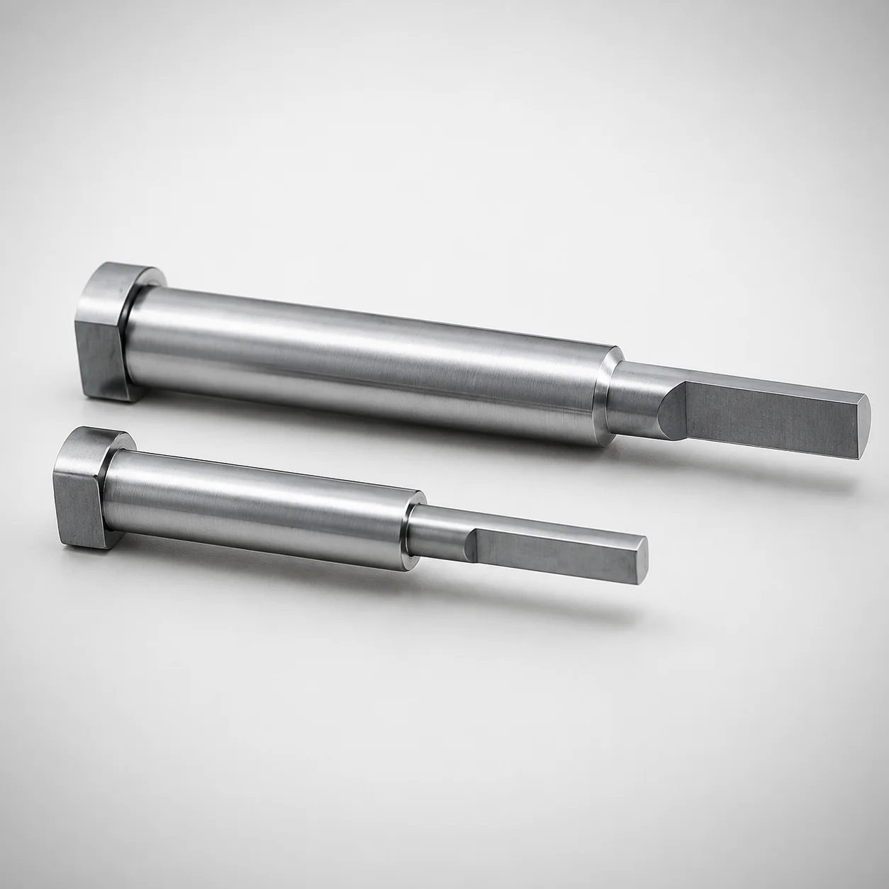
M2 Steel Round Shank Core Pins for Shaft Holes
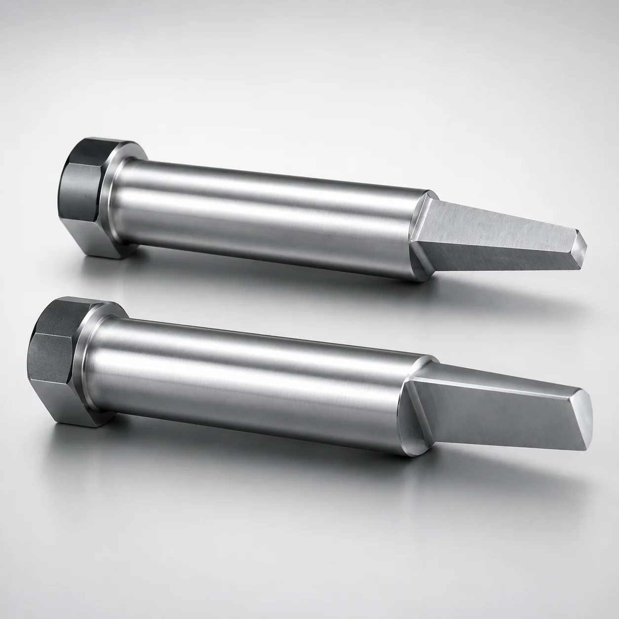
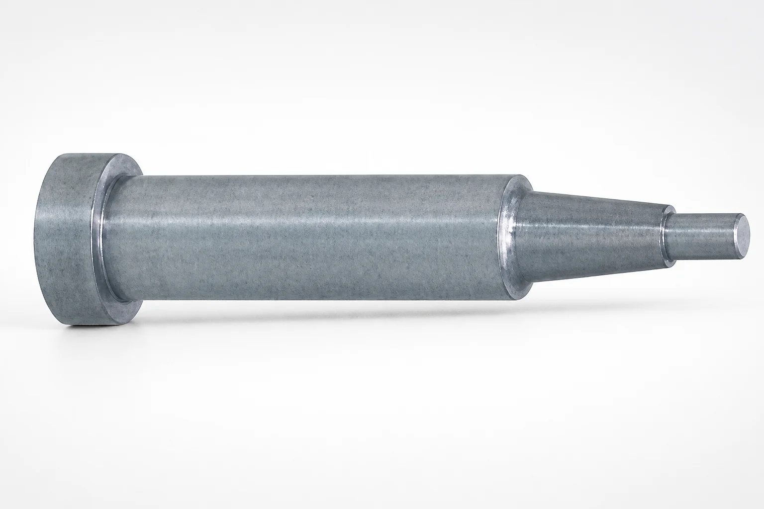
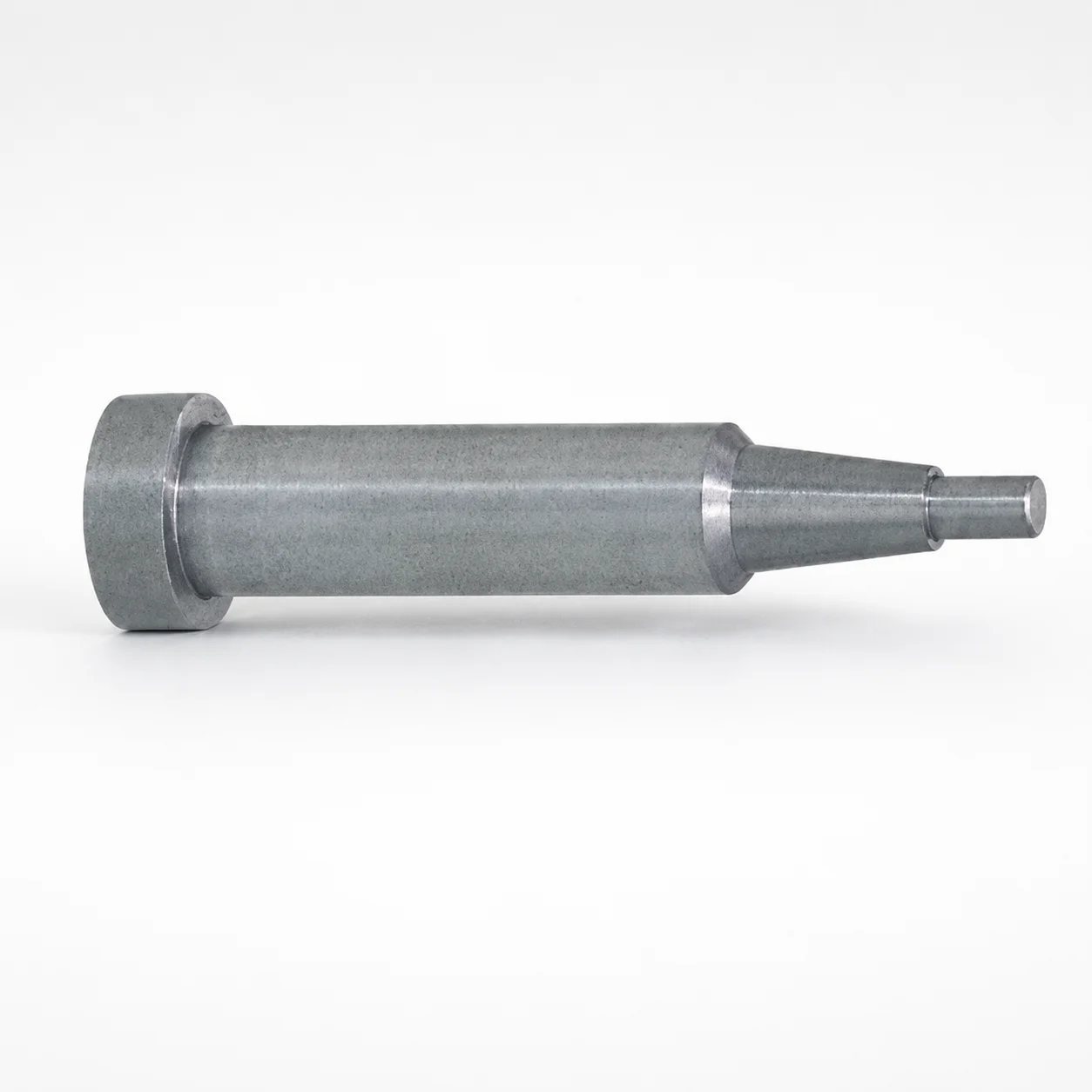
Round shank core pins for shaft holes (M2 steel) are engineered for stable locating and reliable ejection in die and mold assemblies. Their hardened core construction supports repeatable fit while handling production cycle loads.
- Round shank design for accurate shaft-hole alignment and steady positioning
- Built from SKH51 steel with quenched hardened performance for wear resistance
- Controlled L/F dimension tolerance +0.01/0 to support consistent assembly
- Supports tight shaft diameter tolerance 0/-0.005 for reliable press-fit behavior
Specifications
233 configurations available
| Step Shape | Tip Shape | D/P (Shaft Diameter) (mm) | No. (Nominal diameter) (mm) | A (Tip diameter) (mm) | C (Tip part) (mm) | F (Bearing bore length) (mm) | L (L dimension) (mm) | R (Tip part) (mm) | S (Tip part) (mm) | W (Tip part) (mm) | type |
|---|---|---|---|---|---|---|---|---|---|---|---|
| B (for shaft holes) | F | 2 ~ 2.49 | 2.5 | 1.5 ~ 2.49 | - | 20 ~ 96 | 22 ~ 100 | - | 0.5 ~ 35 | 0.75 ~ 2.48 | - |
| B (for shaft holes) | F | 2.5 ~ 2.99 | 3 | 1.5 ~ 2.99 | - | 20 ~ 96 | 22 ~ 100 | - | 0.5 ~ 35 | 0.75 ~ 2.98 | - |
| B (for shaft holes) | F | 3 ~ 3.49 | 3.5 | 1.5 ~ 3.49 | - | 20 ~ 96 | 22 ~ 100 | - | 0.5 ~ 35 | 0.75 ~ 3.48 | - |
| B (for shaft holes) | F | 3.5 ~ 3.99 | 4 | 1.5 ~ 3.99 | - | 20 ~ 96 | 22 ~ 100 | - | 0.5 ~ 35 | 0.75 ~ 3.98 | - |
| B (for shaft holes) | F | 4 ~ 4.49 | 4.5 | 1.5 ~ 4.49 | - | 20 ~ 96 | 22 ~ 100 | - | 0.5 ~ 35 | 0.75 ~ 4.48 | - |
| B (for shaft holes) | F | 4.5 ~ 4.99 | 5 | 1.5 ~ 4.99 | - | 20 ~ 146 | 22 ~ 150 | - | 0.5 ~ 35 | 0.75 ~ 4.98 | - |
| B (for shaft holes) | F | 5 ~ 5.49 | 5.5 | 1.5 ~ 5.49 | - | 20 ~ 146 | 22 ~ 150 | - | 0.5 ~ 35 | 0.75 ~ 5.48 | - |
| B (for shaft holes) | F | 5.5 ~ 5.99 | 6 | 2 ~ 5.99 | - | 20 ~ 146 | 22 ~ 150 | - | 0.5 ~ 35 | 1 ~ 5.98 | - |
| B (for shaft holes) | F | 6 ~ 6.49 | 6.5 | 2 ~ 6.49 | - | 20 ~ 146 | 22 ~ 150 | - | 0.5 ~ 35 | 1 ~ 6.48 | - |
| B (for shaft holes) | F | 6.5 ~ 6.99 | 7 | 2 ~ 6.99 | - | 20 ~ 146 | 22 ~ 150 | - | 0.5 ~ 35 | 1 ~ 6.98 | - |
| B (for shaft holes) | F | 7 ~ 7.99 | 8 | 2 ~ 7.99 | - | 20 ~ 146 | 22 ~ 150 | - | 0.5 ~ 35 | 1 ~ 7.98 | - |
| B (for shaft holes) | F | 8 ~ 9.99 | 10 | 2 ~ 9.99 | - | 20 ~ 146 | 22 ~ 150 | - | 0.5 ~ 35 | 1 ~ 9.98 | - |
| B (for shaft holes) | G | 2 ~ 2.49 | 2.5 | 1.5 ~ 2.48 | - | 20 ~ 96 | 22 ~ 100 | - | 0.5 ~ 35 | 0.75 ~ 2.48 | - |
| B (for shaft holes) | G | 2.5 ~ 2.99 | 3 | 1.5 ~ 2.98 | - | 20 ~ 96 | 22 ~ 100 | - | 0.5 ~ 35 | 0.75 ~ 2.98 | - |
| B (for shaft holes) | G | 3 ~ 3.49 | 3.5 | 1.5 ~ 3.48 | - | 20 ~ 96 | 22 ~ 100 | - | 0.5 ~ 35 | 0.75 ~ 3.48 | - |
| B (for shaft holes) | G | 3.5 ~ 3.99 | 4 | 1.5 ~ 3.98 | - | 20 ~ 96 | 22 ~ 100 | - | 0.5 ~ 35 | 0.75 ~ 3.98 | - |
| B (for shaft holes) | G | 4 ~ 4.49 | 4.5 | 1.5 ~ 4.48 | - | 20 ~ 98 | 22 ~ 100 | - | 0.5 ~ 35 | 0.75 ~ 4.48 | - |
| B (for shaft holes) | G | 4.5 ~ 4.99 | 5 | 1.5 ~ 4.98 | - | 20 ~ 147 | 22 ~ 150 | - | 0.5 ~ 35 | 0.75 ~ 4.98 | - |
| B (for shaft holes) | G | 5 ~ 5.49 | 5.5 | 1.5 ~ 5.48 | - | 20 ~ 147 | 22 ~ 150 | - | 0.5 ~ 35 | 0.75 ~ 5.48 | - |
| B (for shaft holes) | G | 5.5 ~ 5.99 | 6 | 2 ~ 5.98 | - | 20 ~ 147 | 22 ~ 150 | - | 0.5 ~ 35 | 1 ~ 5.98 | - |
| B (for shaft holes) | G | 6 ~ 6.49 | 6.5 | 2 ~ 6.48 | - | 20 ~ 147 | 22 ~ 150 | - | 0.5 ~ 35 | 1 ~ 6.48 | - |
| B (for shaft holes) | G | 6.5 ~ 6.99 | 7 | 2 ~ 6.98 | - | 20 ~ 146 | 22 ~ 150 | - | 0.5 ~ 35 | 1 ~ 6.98 | - |
| B (for shaft holes) | G | 7 ~ 7.99 | 8 | 2 ~ 7.98 | - | 20 ~ 146 | 22 ~ 150 | - | 0.5 ~ 35 | 1 ~ 7.98 | - |
| B (for shaft holes) | G | 8 ~ 9.99 | 10 | 2 ~ 9.98 | - | 20 ~ 146 | 22 ~ 150 | - | 0.5 ~ 35 | 1 ~ 9.98 | - |
| C (for shaft holes) | F | 2 ~ 2.49 | 2.5 | 1.5 ~ 2.49 | - | 20 ~ 96 | 22 ~ 100 | - | 0.5 ~ 35 | 0.75 ~ 2.48 | - |
| C (for shaft holes) | F | 2.5 ~ 2.99 | 3 | 1.5 ~ 2.99 | - | 20 ~ 96 | 22 ~ 100 | - | 0.5 ~ 35 | 0.75 ~ 2.98 | - |
| C (for shaft holes) | F | 3 ~ 3.49 | 3.5 | 1.5 ~ 3.49 | - | 20 ~ 96 | 22 ~ 100 | - | 0.5 ~ 35 | 0.75 ~ 3.48 | - |
| C (for shaft holes) | F | 3.5 ~ 3.99 | 4 | 1.5 ~ 3.99 | - | 20 ~ 96 | 22 ~ 100 | - | 0.5 ~ 35 | 0.75 ~ 3.98 | - |
| C (for shaft holes) | F | 4 ~ 4.49 | 4.5 | 1.5 ~ 4.49 | - | 20 ~ 96 | 22 ~ 100 | - | 0.5 ~ 35 | 0.75 ~ 4.48 | - |
| C (for shaft holes) | F | 4.5 ~ 4.99 | 5 | 1.5 ~ 4.99 | - | 20 ~ 146 | 22 ~ 150 | - | 0.5 ~ 35 | 0.75 ~ 4.98 | - |
| C (for shaft holes) | F | 5 ~ 5.49 | 5.5 | 1.5 ~ 5.49 | - | 20 ~ 146 | 22 ~ 150 | - | 0.5 ~ 35 | 0.75 ~ 5.48 | - |
| C (for shaft holes) | F | 5.5 ~ 5.99 | 6 | 2 ~ 5.99 | - | 20 ~ 146 | 22 ~ 150 | - | 0.5 ~ 35 | 1 ~ 5.98 | - |
| C (for shaft holes) | F | 6 ~ 6.49 | 6.5 | 2 ~ 6.49 | - | 20 ~ 146 | 22 ~ 150 | - | 0.5 ~ 35 | 1 ~ 6.48 | - |
| C (for shaft holes) | F | 6.5 ~ 6.99 | 7 | 2 ~ 6.99 | 0.1 ~ 1 | 20 ~ 146 | 22 ~ 150 | - | 0.5 ~ 35 | 1 ~ 6.98 | - |
| C (for shaft holes) | F | 7 ~ 7.99 | 8 | 2 ~ 7.99 | - | 20 ~ 146 | 22 ~ 150 | - | 0.5 ~ 35 | 1 ~ 7.98 | - |
| C (for shaft holes) | F | 8 ~ 9.99 | 10 | 2 ~ 9.99 | - | 20 ~ 146 | 22 ~ 150 | - | 0.5 ~ 35 | 1 ~ 9.98 | - |
| C (for shaft holes) | G | 2 ~ 2.49 | 2.5 | 1.5 ~ 2.4 | - | 20 ~ 96 | 22 ~ 100 | - | 0.5 ~ 35 | 0.75 ~ 2.48 | - |
| C (for shaft holes) | G | 2.5 ~ 2.99 | 3 | 1.5 ~ 2.9 | - | 20 ~ 96 | 22 ~ 100 | - | 0.5 ~ 35 | 0.75 ~ 2.98 | - |
| C (for shaft holes) | G | 3 ~ 3.49 | 3.5 | 1.5 ~ 3.4 | - | 20 ~ 96 | 22 ~ 100 | - | 0.5 ~ 35 | 0.75 ~ 3.48 | - |
| C (for shaft holes) | G | 3.5 ~ 3.99 | 4 | 1.5 ~ 3.9 | - | 20 ~ 96 | 22 ~ 100 | - | 0.5 ~ 35 | 0.75 ~ 3.98 | - |
| C (for shaft holes) | G | 4 ~ 4.49 | 4.5 | 1.5 ~ 4.4 | - | 20 ~ 96 | 22 ~ 100 | - | 0.5 ~ 35 | 0.75 ~ 4.48 | - |
| C (for shaft holes) | G | 4.5 ~ 4.99 | 5 | 1.5 ~ 4.9 | - | 20 ~ 146 | 22 ~ 150 | - | 0.5 ~ 35 | 0.75 ~ 4.98 | - |
| C (for shaft holes) | G | 5 ~ 5.49 | 5.5 | 1.5 ~ 5.4 | - | 20 ~ 146 | 22 ~ 150 | - | 0.5 ~ 35 | 0.75 ~ 5.48 | - |
| C (for shaft holes) | G | 5.5 ~ 5.99 | 6 | 2 ~ 5.9 | - | 20 ~ 146 | 22 ~ 150 | - | 0.5 ~ 35 | 1 ~ 5.98 | - |
| C (for shaft holes) | G | 6 ~ 6.49 | 6.5 | 2 ~ 6.4 | - | 20 ~ 146 | 22 ~ 150 | - | 0.5 ~ 35 | 1 ~ 6.48 | - |
| C (for shaft holes) | G | 6.5 ~ 6.99 | 7 | 2 ~ 6.9 | - | 20 ~ 146 | 22 ~ 150 | - | 0.5 ~ 35 | 1 ~ 6.98 | - |
| C (for shaft holes) | G | 7 ~ 7.99 | 8 | 2 ~ 7.9 | - | 20 ~ 146 | 22 ~ 150 | - | 0.5 ~ 35 | 1 ~ 7.98 | - |
| C (for shaft holes) | G | 8 ~ 9.99 | 10 | 2 ~ 9.9 | - | 20 ~ 146 | 22 ~ 150 | - | 0.5 ~ 35 | 1 ~ 9.98 | - |
| D (for shaft holes) | F | 2 ~ 2.49 | 2.5 | 1.5 ~ 2.49 | 0.1 ~ 1 | 20 ~ 96 | 22 ~ 100 | - | 0.5 ~ 35 | 0.75 ~ 2.48 | - |
| D (for shaft holes) | F | 2.5 ~ 2.99 | 3 | 1.5 ~ 2.99 | 0.1 ~ 1 | 20 ~ 96 | 22 ~ 100 | - | 0.5 ~ 35 | 0.75 ~ 2.98 | - |
Product Guide
Application Scenarios+
Round shank core pins are used to form and maintain precise shaft holes in multi-cavity injection mold assemblies, where consistent alignment directly impacts assembly of inserts, mechanisms, and mating parts.
- Automotive connector housings: The quenched-hardened SKH51 construction and controlled shaft-hole interfaces help maintain dimensional stability over production cycles, supporting repeatable alignment for snap-fit or press-fit features.
- Consumer appliance latch/hinge components: The round shank geometry steadies the pin during ejection, reducing the risk of hole-position drift that can cause misalignment with shafts.
- Industrial device housings: Tight control of the shaft diameter and the L/F tolerance supports consistent core-to-cavity registration, improving repeatability for downstream assembly.
With the specified shaft-hole step/tip shapes (B/C/D/E for shaft holes and F/G for tip shape), this variant is suited for designs that require reliable locating and repeatable press-fit behavior.
Material & Process Details+
This core pin uses SKH51 steel in a quenched hardened condition. SKH51 corresponds to AISI M2 (high-speed steel family), providing excellent wear resistance for hardened core applications where friction and repeated ejection loads are present.
- Heat treatment: quenched & hardened performance state to improve hardness and surface durability.
- Hardness / wear vs. toughness: the hardened condition increases resistance to wear and micro-abrasion at the bearing bore interface, while potentially reducing impact toughness compared with softer pre-hardened steels—so design relies on proper support and alignment.
- Manufacturing approach: typically produced via precision machining of the round shank and tip geometry, followed by hardening to achieve stable dimensions for tight press-fit hole formation.
Compared to general purpose tool steels, this SKH51 construction is better when long production runs demand higher wear resistance at the shaft-hole interface.
Sizing & Selection Guide+
Select the pin variant by matching the shaft diameter (D/P) and overall length L to your core-to-cavity requirements for the shaft-hole feature.
- Shaft diameter: choose D/P = 2 ~ 10 mm to match the target hole/shaft interface. Confirm the pin-to-hole fit requirement using the specified shaft diameter tolerance 0/-0.005 (press-fit tendency).
- Nominal diameter: the corresponding nominial diameter = 2.5 ~ 10 mm should be consistent with your drawing’s core pin bore/guide specification.
- Length (L): choose L = 22 ~ 100 mm or up to 22 ~ 150 mm depending on tool stack-up. The L/F dimension tolerance +0.01/0 supports repeatable alignment during assembly.
- Tip and step shapes: use the specified Step shape B/C/D/E for shaft holes and the Tip shape F or G to match the bearing bore length and lead-in behavior.
Verify the bearing bore length F = 20 ~ 96/98/99/146/147/149 mm so the created shaft hole depth and engagement length meet the functional requirement.
Frequently Asked Questions
How does the SKH51 (AISI M2 equivalent) quenched-hardened condition affect wear at the shaft-hole interface?+
What should I match when selecting the pin for a specific shaft diameter and press-fit behavior?+
How do I choose the correct L and F dimensions for repeatable alignment in a stacked core insert?+
Which tip/step shape options (B/C/D/E and F/G) are relevant to shaft-hole designs?+
What tolerance guidance should I use for integrating this pin into the tool design?+
Related Products
Need Custom Specifications?
Our engineering team can help with custom configurations, material selection, and volume pricing.