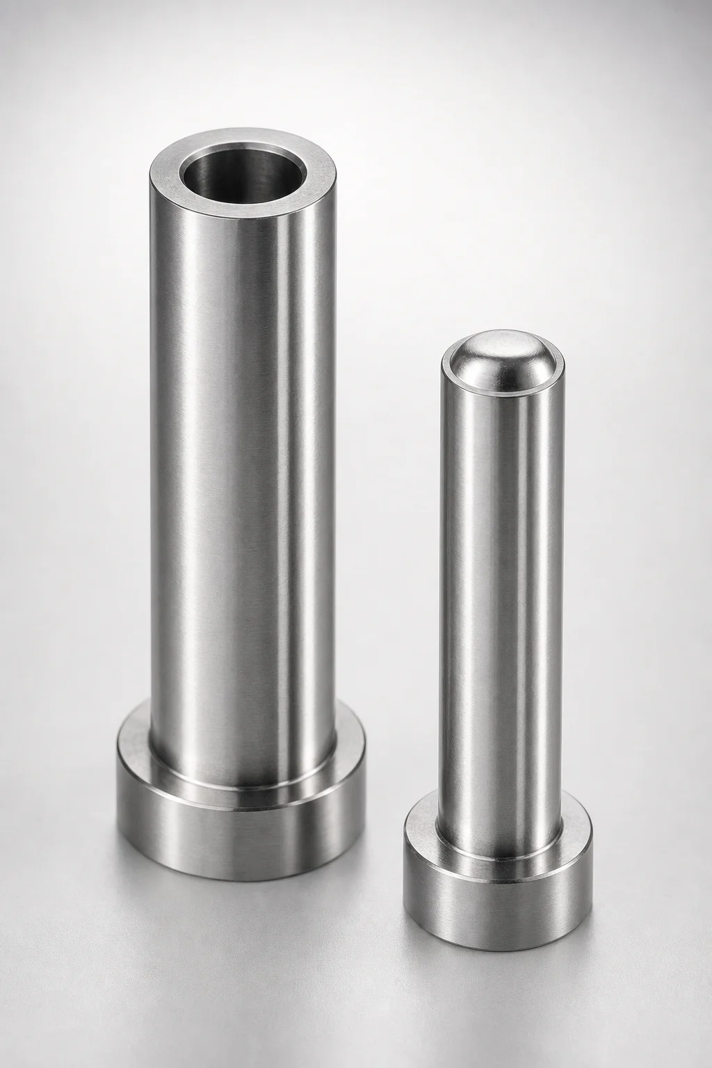
Gas Release Round Core Pins Flat-Sided
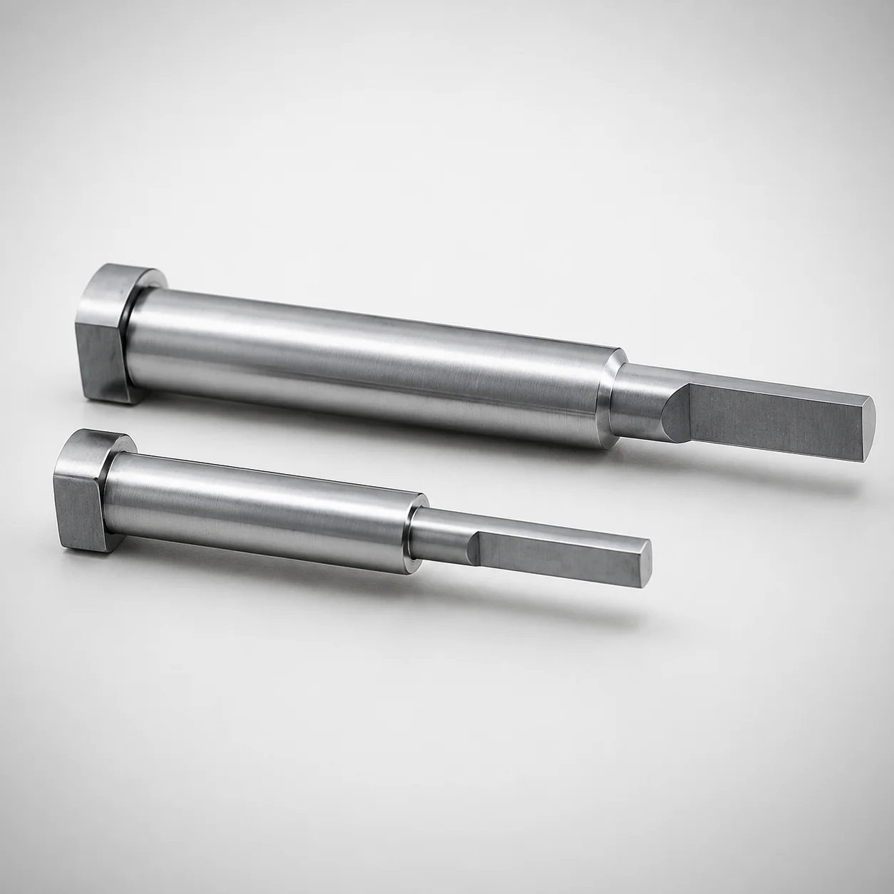
Gas release round core pins (hardened steel) are designed for reliable boss-shape alignment, while the flat-sided anti-rotation surface helps maintain consistent positioning during assembly and production. The built-in gas vent feature supports efficient mold exhaust and improves operational stability.
- Built-in gas release design (gas vent) for improved mold exhaust efficiency
- Flat-Sided anti-rotation head for stable core positioning and accurate alignment
- Quenched hardened steel construction for wear resistance under repeated cycles
- Made for precision mechanical assemblies and high-repeat molding applications
Specifications
886 configurations available
| Material | Shaft Diameter Tolerance | Hole Tolerance | D/P (Shaft Diameter) (mm) | Hole Shape Type | No. (Nominal diameter) (mm) | A (Hole diameter) (mm) | B (Hole depth) (mm) | C (Chamfering width) (mm) | G (Chamfering width) (mm) | L (L dimension) (mm) | Q (Hole shape R) (mm) | R (Hole end face R) (mm) | SR (Radius of hole's spherical surface) (mm) | type |
|---|---|---|---|---|---|---|---|---|---|---|---|---|---|---|
| SKD61 | -0.01/-0.02 | 0/-0.04 | 1.5 ~ 1.99 | BL | 2 | - | 0.3 ~ 3 | - | - | 10 ~ 100 | - | - | 1.2 ~ 3.98 | - |
| SKD61 | -0.01/-0.02 | 0/-0.04 | 2 ~ 2.49 | BL | 2.5 | - | 0.3 ~ 3 | - | - | 10 ~ 100 | - | - | 1.6 ~ 4.98 | - |
| SKD61 | -0.01/-0.02 | 0/-0.04 | 2.5 ~ 2.99 | BL | 3 | - | 0.3 ~ 3 | - | - | 10 ~ 100 | - | - | 2 ~ 5.98 | - |
| SKD61 | -0.01/-0.02 | 0/-0.04 | 3 ~ 3.49 | BL | 3.5 | - | 0.3 ~ 3 | - | - | 10 ~ 120 | - | - | 2.4 ~ 6.98 | - |
| SKD61 | -0.01/-0.02 | 0/-0.04 | 3.5 ~ 3.99 | BL | 4 | - | 0.3 ~ 3 | - | - | 10 ~ 120 | - | - | 2.8 ~ 7.98 | - |
| SKD61 | -0.01/-0.02 | 0/-0.04 | 4 ~ 4.49 | BL | 4.5 | - | 0.3 ~ 3 | - | - | 10 ~ 120 | - | - | 3.2 ~ 8.98 | - |
| SKD61 | -0.01/-0.02 | 0/-0.04 | 4.5 ~ 4.99 | BL | 5 | - | 0.3 ~ 3 | - | - | 10 ~ 120 | - | - | 3.6 ~ 9.98 | - |
| SKD61 | -0.01/-0.02 | 0/-0.04 | 5 ~ 5.49 | BL | 5.5 | - | 0.3 ~ 3 | - | - | 10 ~ 120 | - | - | 4 ~ 10.98 | - |
| SKD61 | -0.01/-0.02 | 0/-0.04 | 5.5 ~ 5.99 | BL | 6 | - | 0.3 ~ 3 | - | - | 10 ~ 120 | - | - | 4.4 ~ 11.98 | - |
| SKD61 | -0.01/-0.02 | 0/-0.04 | 6 ~ 6.49 | BL | 6.5 | - | 0.3 ~ 3 | - | - | 10 ~ 120 | - | - | 4.8 ~ 12.98 | - |
| SKD61 | -0.01/-0.02 | 0/-0.04 | 6.5 ~ 6.99 | BL | 7 | - | 0.3 ~ 3 | - | - | 10 ~ 120 | - | - | 5.2 ~ 13.98 | - |
| SKD61 | -0.01/-0.02 | 0/-0.04 | 7 ~ 7.99 | BL | 8 | - | 0.3 ~ 3 | - | - | 10 ~ 120 | - | - | 5.6 ~ 15.98 | - |
| SKD61 | -0.01/-0.02 | 0/-0.04 | 1.5 ~ 1.99 | BS | 2 | - | 0.3 ~ 3 | - | - | 10 ~ 100 | - | - | 0.5 ~ 3.98 | - |
| SKD61 | -0.01/-0.02 | 0/-0.04 | 2 ~ 2.49 | BS | 2.5 | - | 0.3 ~ 3 | - | - | 10 ~ 100 | - | - | 0.5 ~ 4.98 | - |
| SKD61 | -0.01/-0.02 | 0/-0.04 | 2.5 ~ 2.99 | BS | 3 | - | 0.3 ~ 3 | - | - | 10 ~ 100 | - | - | 0.5 ~ 5.98 | - |
| SKD61 | -0.01/-0.02 | 0/-0.04 | 3 ~ 3.49 | BS | 3.5 | - | 0.3 ~ 3 | - | - | 10 ~ 120 | - | - | 0.5 ~ 6.98 | - |
| SKD61 | -0.01/-0.02 | 0/-0.04 | 3.5 ~ 3.99 | BS | 4 | - | 0.3 ~ 3 | - | - | 10 ~ 120 | - | - | 0.5 ~ 7.98 | - |
| SKD61 | -0.01/-0.02 | 0/-0.04 | 4 ~ 4.49 | BS | 4.5 | - | 0.3 ~ 3 | - | - | 10 ~ 120 | - | - | 0.5 ~ 8.98 | - |
| SKD61 | -0.01/-0.02 | 0/-0.04 | 4.5 ~ 4.99 | BS | 5 | - | 0.3 ~ 3 | - | - | 10 ~ 120 | - | - | 0.5 ~ 9.98 | - |
| SKD61 | -0.01/-0.02 | 0/-0.04 | 5 ~ 5.49 | BS | 5.5 | - | 0.3 ~ 3 | - | - | 10 ~ 120 | - | - | 0.5 ~ 10.98 | - |
| SKD61 | -0.01/-0.02 | 0/-0.04 | 5.5 ~ 5.99 | BS | 6 | - | 0.3 ~ 3 | - | - | 10 ~ 120 | - | - | 0.5 ~ 11.98 | - |
| SKD61 | -0.01/-0.02 | 0/-0.04 | 6 ~ 6.49 | BS | 6.5 | - | 0.3 ~ 3 | - | - | 10 ~ 120 | - | - | 0.5 ~ 12.98 | - |
| SKD61 | -0.01/-0.02 | 0/-0.04 | 6.5 ~ 6.99 | BS | 7 | - | 0.3 ~ 3 | - | - | 10 ~ 120 | - | - | 0.5 ~ 13.98 | - |
| SKD61 | -0.01/-0.02 | 0/-0.04 | 7 ~ 7.99 | BS | 8 | - | 0.3 ~ 3 | - | - | 10 ~ 120 | - | - | 0.5 ~ 15.98 | - |
| SKD61 | -0.01/-0.02 | 0/-0.04 | 2 ~ 2.49 | CG | 2.5 | 1 ~ 1.49 | 0.5 ~ 3 | 0.2 ~ 0.5 | 0.25 ~ 1 | 10 ~ 100 | - | - | - | - |
| SKD61 | -0.01/-0.02 | 0/-0.04 | 2.5 ~ 2.99 | CG | 3 | 1 ~ 1.99 | 0.5 ~ 3 | 0.2 ~ 0.5 | 0.25 ~ 1 | 10 ~ 100 | - | - | - | - |
| SKD61 | -0.01/-0.02 | 0/-0.04 | 3 ~ 3.49 | CG | 3.5 | 1 ~ 2.49 | 0.5 ~ 3 | 0.2 ~ 0.5 | 0.25 ~ 1 | 10 ~ 120 | - | - | - | - |
| SKD61 | -0.01/-0.02 | 0/-0.04 | 3.5 ~ 3.99 | CG | 4 | 1 ~ 2.99 | 0.5 ~ 3 | 0.2 ~ 0.5 | 0.25 ~ 1 | 10 ~ 120 | - | - | - | - |
| SKD61 | -0.01/-0.02 | 0/-0.04 | 4 ~ 4.49 | CG | 4.5 | 1 ~ 3.49 | 0.5 ~ 3 | 0.2 ~ 0.5 | 0.25 ~ 1 | 10 ~ 120 | - | - | - | - |
| SKD61 | -0.01/-0.02 | 0/-0.04 | 4.5 ~ 4.99 | CG | 5 | 1 ~ 3.49 | 0.5 ~ 3 | 0.2 ~ 0.5 | 0.25 ~ 1 | 10 ~ 120 | - | - | - | - |
| SKD61 | -0.01/-0.02 | 0/-0.04 | 5 ~ 5.49 | CG | 5.5 | 1 ~ 3.99 | 0.5 ~ 3 | 0.2 ~ 0.5 | 0.25 ~ 1 | 10 ~ 120 | - | - | - | - |
| SKD61 | -0.01/-0.02 | 0/-0.04 | 5.5 ~ 5.99 | CG | 6 | 1 ~ 4.49 | 0.5 ~ 3 | 0.2 ~ 0.5 | 0.25 ~ 1 | 10 ~ 120 | - | - | - | - |
| SKD61 | -0.01/-0.02 | 0/-0.04 | 6 ~ 6.49 | CG | 6.5 | 1 ~ 4.99 | 0.5 ~ 3 | 0.2 ~ 0.5 | 0.25 ~ 1 | 10 ~ 120 | - | - | - | - |
| SKD61 | -0.01/-0.02 | 0/-0.04 | 6.5 ~ 6.99 | CG | 7 | 1 ~ 4.99 | 0.5 ~ 3 | 0.2 ~ 0.5 | 0.25 ~ 1 | 10 ~ 120 | - | - | - | - |
| SKD61 | -0.01/-0.02 | 0/-0.04 | 7 ~ 7.99 | CG | 8 | 1 ~ 5.99 | 0.5 ~ 3 | 0.2 ~ 0.5 | 0.25 ~ 1 | 10 ~ 120 | - | - | - | - |
| SKD61 | -0.01/-0.02 | 0/-0.04 | 2 ~ 2.49 | CQ | 2.5 | 1 ~ 1.49 | 0.5 ~ 3 | 0.2 ~ 0.5 | - | 10 ~ 100 | 0.25 ~ 1 | - | - | - |
| SKD61 | -0.01/-0.02 | 0/-0.04 | 2.5 ~ 2.99 | CQ | 3 | 1 ~ 1.99 | 0.5 ~ 3 | 0.2 ~ 0.5 | - | 10 ~ 100 | 0.25 ~ 1 | - | - | - |
| SKD61 | -0.01/-0.02 | 0/-0.04 | 3 ~ 3.49 | CQ | 3.5 | 1 ~ 2.49 | 0.5 ~ 3 | 0.2 ~ 0.5 | - | 10 ~ 120 | 0.25 ~ 1 | - | - | - |
| SKD61 | -0.01/-0.02 | 0/-0.04 | 3.5 ~ 3.99 | CQ | 4 | 1 ~ 2.99 | 0.5 ~ 3 | 0.2 ~ 0.5 | - | 10 ~ 120 | 0.25 ~ 1 | - | - | - |
| SKD61 | -0.01/-0.02 | 0/-0.04 | 4 ~ 4.49 | CQ | 4.5 | 1 ~ 3.49 | 0.5 ~ 3 | 0.2 ~ 0.5 | - | 10 ~ 120 | 0.25 ~ 1 | - | - | - |
| SKD61 | -0.01/-0.02 | 0/-0.04 | 4.5 ~ 4.99 | CQ | 5 | 1 ~ 3.49 | 0.5 ~ 3 | 0.2 ~ 0.5 | - | 10 ~ 120 | 0.25 ~ 1 | - | - | - |
| SKD61 | -0.01/-0.02 | 0/-0.04 | 5 ~ 5.49 | CQ | 5.5 | 1 ~ 3.99 | 0.5 ~ 3 | 0.2 ~ 0.5 | - | 10 ~ 120 | 0.25 ~ 1 | - | - | - |
| SKD61 | -0.01/-0.02 | 0/-0.04 | 5.5 ~ 5.99 | CQ | 6 | 1 ~ 4.49 | 0.5 ~ 3 | 0.2 ~ 0.5 | - | 10 ~ 120 | 0.25 ~ 1 | - | - | - |
| SKD61 | -0.01/-0.02 | 0/-0.04 | 6 ~ 6.49 | CQ | 6.5 | 1 ~ 4.99 | 0.5 ~ 3 | 0.2 ~ 0.5 | - | 10 ~ 120 | 0.25 ~ 1 | - | - | - |
| SKD61 | -0.01/-0.02 | 0/-0.04 | 6.5 ~ 6.99 | CQ | 7 | 1 ~ 4.99 | 0.5 ~ 3 | 0.2 ~ 0.5 | - | 10 ~ 120 | 0.25 ~ 1 | - | - | - |
| SKD61 | -0.01/-0.02 | 0/-0.04 | 7 ~ 7.99 | CQ | 8 | 1 ~ 5.99 | 0.5 ~ 3 | 0.2 ~ 0.5 | - | 10 ~ 120 | 0.25 ~ 1 | - | - | - |
| SKD61 | -0.01/-0.02 | 0/-0.04 | 2 ~ 2.49 | CS | 2.5 | 1 ~ 1.49 | 0.5 ~ 3 | 0.2 ~ 0.5 | - | 10 ~ 100 | - | - | - | - |
| SKD61 | -0.01/-0.02 | 0/-0.04 | 2.5 ~ 2.99 | CS | 3 | 1 ~ 1.99 | 0.5 ~ 3 | 0.2 ~ 0.5 | - | 10 ~ 100 | - | - | - | - |
| SKD61 | -0.01/-0.02 | 0/-0.04 | 3 ~ 3.49 | CS | 3.5 | 1 ~ 2.49 | 0.5 ~ 3 | 0.2 ~ 0.5 | - | 10 ~ 120 | - | - | - | - |
| SKD61 | -0.01/-0.02 | 0/-0.04 | 3.5 ~ 3.99 | CS | 4 | 1 ~ 2.99 | 0.5 ~ 3 | 0.2 ~ 0.5 | - | 10 ~ 120 | - | - | - | - |
Product Guide
Application Scenarios+
Core boss-inlay alignment and venting are typical needs in multi-part injection molds where the boss geometry must stay concentric across repeated cycles. This flat-sided anti-rotation core pin variant uses the gas vent feature to promote consistent exhaust, reducing trapped gas risks and helping maintain stable cavity pressure during filling.
In automotive connector and housing molds, the flat-sided head prevents unwanted rotation during assembly, which improves boss position accuracy for mating components. The hardened steel construction supports wear under continuous movement between cycles.
For electronics and small appliance housings, accurate inlay alignment is critical to avoid downstream fit issues. The available shaft diameter range supports tight hole-to-boss interfaces, while the built-in gas release supports smoother venting in fine-gauge details.
- Gas exhaust support: built-in venting reduces trapped air effects.
- Anti-rotation positioning: flat-sided head maintains boss alignment.
- Stable wear performance: hardened steel supports repeat molding.
Material & Process Details+
This core pin family is offered in SKD61 or SKH51 steels, both chosen for injection mold tooling durability. SKD61 is widely used as an H13-equivalent hot-work tool steel, providing a good balance of toughness and tempering stability for cores that see heating and repeated cycles. SKH51 corresponds to an AISI M2-equivalent high-speed steel, generally prioritizing wear resistance where sliding contact or abrasion is a concern.
- Heat treatment state: hardened steel construction is used for stable positioning and wear performance under repeated operation.
- Hardness & trade-offs: both options are intended for wear resistance; SKH51 typically offers higher wear performance, while SKD61 is often selected where toughness and thermal stability matter more.
- Manufacturing process: precision machining for shaft and flat-sided anti-rotation features, followed by hardening and tempering appropriate to the selected grade.
Note: exact HRC values are not provided in the available specification data.
Sizing & Selection Guide+
To select the correct core pin dimensions, match the D/P (shaft diameter) to the boss-inlay hole size in your core block. The available D/P range is 1.5 to 8 mm, with shaft diameter tolerances of -0.01/-0.02 or 0/-0.005 depending on the part/option.
Next, verify the hole geometry in the mold design using the provided hole shape codes (BL, BS, CG, CQ, CS, RG, RQ, RS, SG, SQ, SS). The hole diameter A is specified as 1 to 1 mm (fixed range in the data), while hole depth B is available in 0.3–3 mm, 0.5–3 mm, or 0–3 mm.
- L length: choose 10–100 mm or 10–120 mm based on core thickness and support length needs.
- Chamfering: chamfer widths are fixed as C: 0.2–0.5 mm and G: 0.25–1 mm, which should align with your hole entry relief.
- Hole tolerance: hole tolerance is 0/-0.04, 0/-0.02, or 0/-0.01; use this to confirm fit (slip vs. press) between hole and pin.
Also confirm SR (hole spherical surface radius, 0.5–6.4 mm) and the end features (Q and R) to ensure proper seating of the gas-release/inlay interface.
Frequently Asked Questions
Which steel grade should I choose for a gas-release round core pin: SKD61 or SKH51?+
The product is offered in SKD61 and SKH51. Use SKD61 when you need a tough H13-equivalent balance for repeated cycles with thermal stability. Choose SKH51 when you prioritize higher wear resistance for abrasion-prone or frequently contacting interfaces.
How do I select the correct shaft diameter (D/P) and ensure the fit with the mating hole tolerance?+
Select D/P within 1.5–8 mm and align it with your core hole diameter tolerance. The pin shaft diameter tolerance options are -0.01/-0.02 or 0/-0.005, while the hole tolerance is 0/-0.04, 0/-0.02, or 0/-0.01. Match these to achieve your intended clearance/fit and avoid assembly binding or excessive play.
What hole depth (B) and length (L) values are available for boss alignment applications?+
The hole depth B is available in 0.3–3 mm, 0.5–3 mm, or 0–3 mm, depending on the configuration. The pin length L is available in 10–100 mm and 10–120 mm. Use L to match core thickness and required engagement length for stable alignment.
Do the flat-sided anti-rotation features affect how I design the hole shape for installation?+
The pin includes a flat-sided anti-rotation head to prevent rotation during assembly and molding. Because hole geometry options (BL, BS, CG, CQ, CS, RG, RQ, RS, SG, SQ, SS) are selectable, confirm that your core pocket/hole shape matches the intended variant for correct seating and orientation. Use the provided chamfer ranges (C 0.2–0.5 mm and G 0.25–1 mm) to ensure proper entry and reduced edge loading.
How do the gas vent and spherical interface dimensions influence venting performance at the core pin location?+
This design incorporates a gas release (gas vent) to support efficient mold exhaust near the boss-inlay region. To maintain the intended interface around the vent path, ensure the spherical surface radius SR (0.5–6.4 mm) and the hole-end features Q (0.25–1 mm) and R (0.3–0.5 mm) match the mating geometry. Correct interface geometry helps stabilize the sealing/venting behavior and reduces variability across cycles.
Related Products
Need Custom Specifications?
Our engineering team can help with custom configurations, material selection, and volume pricing.