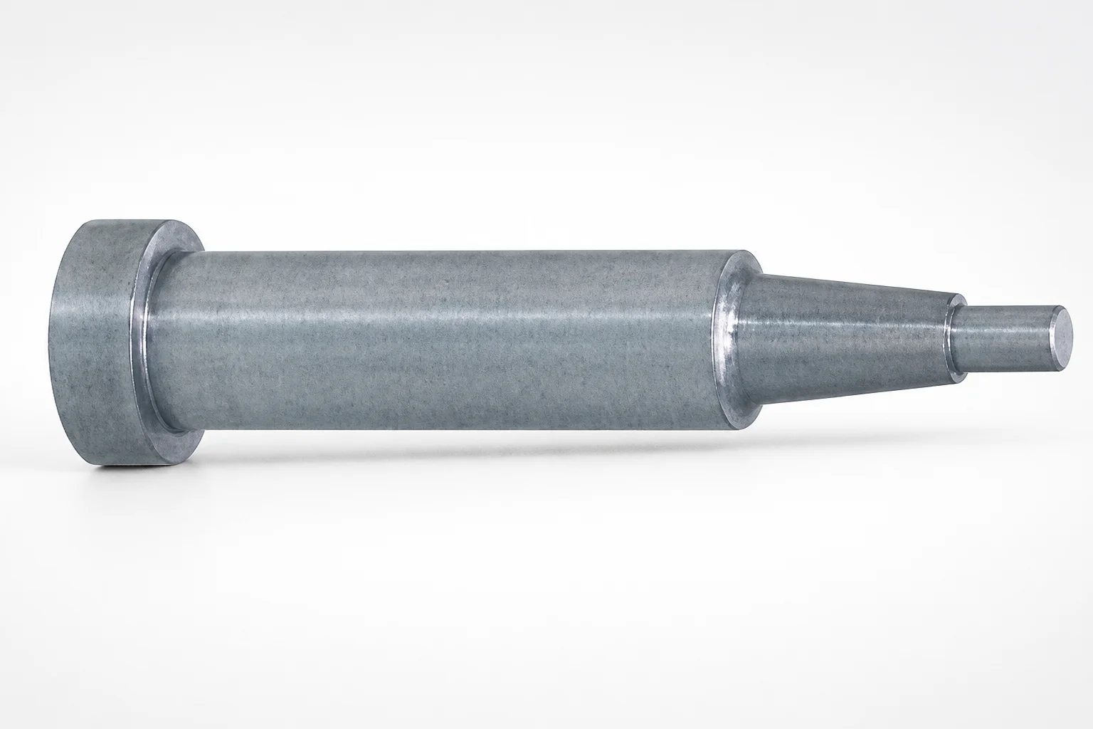
Inlay Core Pins M2 Steel
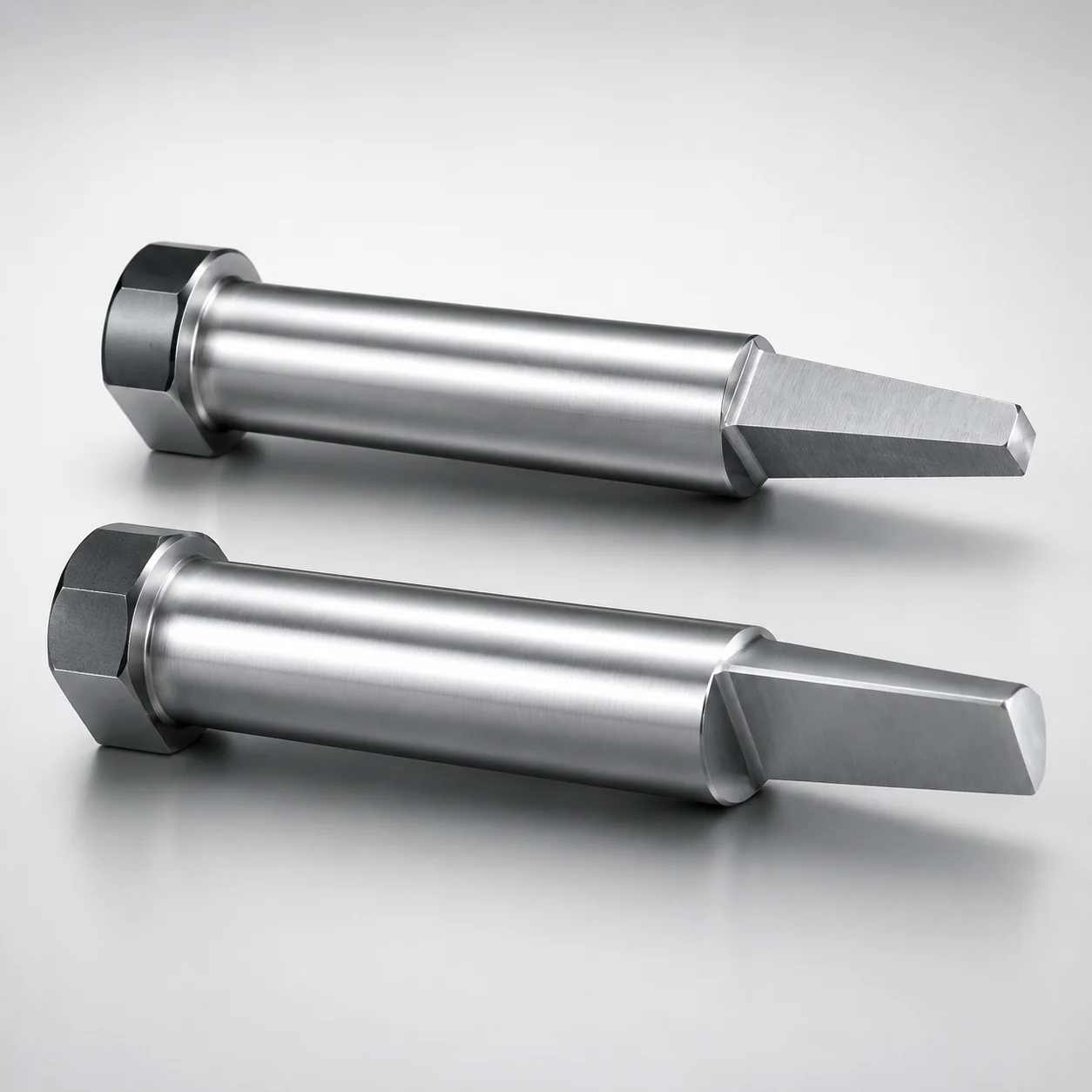
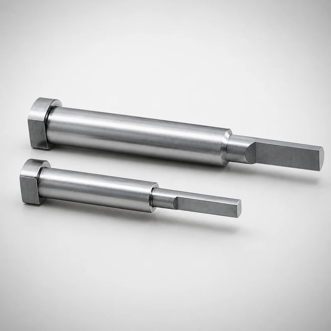
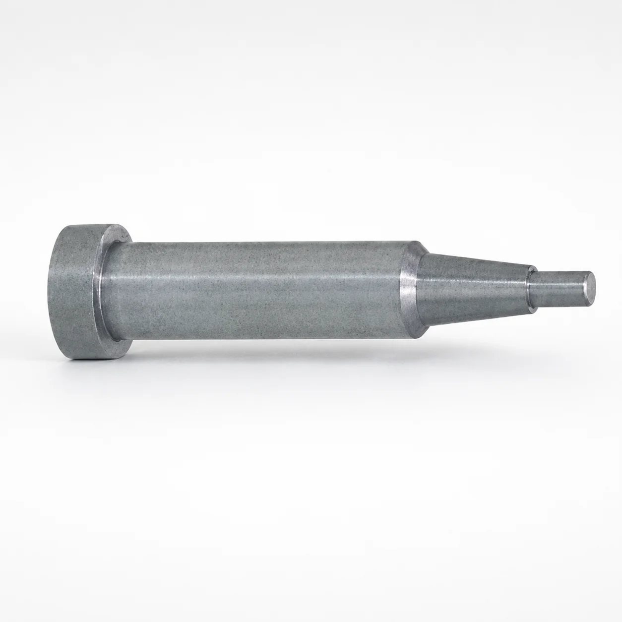
Inlay core pins (M2 steel) are engineered for precision mold inlay applications, offering a configurable shaft diameter to achieve reliable alignment and consistent support in demanding production. Their durable construction helps minimize wear while maintaining dimensional stability.
- Configurable shaft diameter supports tailored fit for core and insert positioning
- Built from M2 steel to deliver wear resistance for long service life
- Machined for tight shaft diameter tolerance compatibility in precision assemblies
- Suitable for high-precision molds where stable operation and repeatability are critical
Specifications
348 configurations available
| Material | Shaft Diameter Tolerance | D/P (Shaft Diameter) (mm) | Tip Step Shape | L Dimension Tolerance | Tip Gradient Tolerance | A (Step shape diameter) (mm) | B (Inlay section length) (mm) | C (Tip part) (mm) | F (Bearing bore length) (mm) | L (L dimension) (mm) | R (Tip part) (mm) | S (Inlay section diameter) (mm) | V (Tip part) (mm) | type |
|---|---|---|---|---|---|---|---|---|---|---|---|---|---|---|
| SKD61 | -0.01/-0.02 | 1.5 | A | +0.02/0 | ±0.015 | - | 0.7 ~ 7.4 | - | 10 ~ 96 | 12 �� 99.3 | - | 0.5 ~ 1.49 | 0.51 ~ 1.49 | - |
| SKD61 | -0.01/-0.02 | 2 | A | +0.02/0 | ±0.015 | - | 0.7 ~ 14.8 | - | 10 ~ 96 | 12 ~ 99.3 | - | 0.7 ~ 1.99 | 0.71 ~ 1.99 | - |
| SKD61 | -0.01/-0.02 | 2.5 | A | +0.02/0 | ±0.015 | - | 0.1 ~ 12.3 | - | 10 ~ 96 | 12 ~ 99.3 | - | 0.7 ~ 2.48 | 0.8 ~ 2.5 | - |
| SKD61 | -0.01/-0.02 | 3 | A | +0.02/0 | ±0.015 | - | 0.1 ~ 14.8 | - | 10 ~ 96 | 12 ~ 99.3 | - | 1 ~ 2.98 | 1.1 ~ 3 | - |
| SKD61 | -0.01/-0.02 | 3.5 | A | +0.02/0 | ±0.015 | - | 0.1 ~ 17.3 | - | 10 ~ 110 | 12 ~ 119.3 | - | 1 ~ 3.48 | 1.1 ~ 3.5 | - |
| SKD61 | -0.01/-0.02 | 4 | A | +0.02/0 | ±0.015 | - | 0.1 ~ 19.8 | - | 10 ~ 110 | 12 ~ 119.3 | - | 1 ~ 3.98 | 1.1 ~ 4 | - |
| SKD61 | -0.01/-0.02 | 4.5 | A | +0.02/0 | ±0.015 | - | 0.1 ~ 22.3 | - | 10 ~ 110 | 12 ~ 119.3 | - | 1.5 ~ 4.48 | 1.51 ~ 4.5 | - |
| SKD61 | -0.01/-0.02 | 5 | A | +0.02/0 | ±0.015 | - | 0.1 ~ 24.8 | - | 10 ~ 110 | 12 ~ 119.3 | - | 1.5 ~ 4.98 | 1.51 ~ 5 | - |
| SKD61 | -0.01/-0.02 | 5.5 | A | +0.02/0 | ±0.015 | - | 0.1 ~ 27.3 | - | 10 ~ 110 | 12 ~ 119.3 | - | 1.5 ~ 5.48 | 1.51 ~ 5.5 | - |
| SKD61 | -0.01/-0.02 | 6 | A | +0.02/0 | ±0.015 | - | 0.1 ~ 29.8 | - | 10 ~ 110 | 12 ~ 119.3 | - | 2 ~ 5.98 | 2.01 ~ 6 | - |
| SKD61 | -0.01/-0.02 | 6.5 | A | +0.02/0 | ±0.015 | - | 0.1 ~ 32.3 | - | 10 ~ 110 | 12 ~ 119.3 | - | 2 ~ 6.48 | 2.1 ~ 6.5 | - |
| SKD61 | -0.01/-0.02 | 7 | A | +0.02/0 | ±0.015 | - | 0.1 ~ 34.8 | - | 10 ~ 110 | 12 ~ 119.3 | - | 2 ~ 6.98 | 2.1 ~ 7 | - |
| SKD61 | -0.01/-0.02 | 8 | A | +0.02/0 | ±0.015 | - | 0.1 ~ 38.8 | - | 10 ~ 110 | 12 ~ 119.3 | - | 2 ~ 7.98 | 2.1 ~ 8 | - |
| SKD61 | -0.01/-0.02 | 10 | A | +0.02/0 | ±0.015 | - | 0.1 ~ 49.8 | - | 10 ~ 110 | 12 ~ 119.3 | - | 2 ~ 9.98 | 2.1 ~ 10 | - |
| SKD61 | -0.01/-0.02 | 13 | A | +0.02/0 | ±0.015 | - | 0.1 ~ 64.5 | - | 10 ~ 119.5 | 12 ~ 120 | - | 2.5 ~ 12.98 | 2.51 ~ 13 | - |
| SKD61 | -0.01/-0.02 | 16 | A | +0.02/0 | ±0.015 | - | 0.7 ~ 79.8 | - | 10 ~ 116 | 12 ~ 120 | - | 2.5 ~ 15.98 | 2.6 ~ 16 | - |
| SKD61 | -0.01/-0.02 | 20 | A | +0.02/0 | ±0.015 | - | 0.7 ~ 91.5 | - | 28 ~ 110 | 30 ~ 119.3 | - | 5 ~ 19.99 | 5.01 ~ 19.99 | - |
| SKD61 | -0.01/-0.02 | 1.5 | B | +0.02/0 | ±0.015 | 0.51 ~ 1.49 | 0.7 ~ 7.4 | - | 10 ~ 96 | 12 ~ 99.3 | - | 0.5 ~ 1.49 | 0.51 ~ 1.49 | - |
| SKD61 | -0.01/-0.02 | 2 | B | +0.02/0 | ±0.015 | 0.71 ~ 1.99 | 0.7 ~ 14.8 | - | 10 ~ 96 | 12 ~ 99.3 | - | 0.7 ~ 1.99 | 0.71 ~ 1.99 | - |
| SKD61 | -0.01/-0.02 | 2.5 | B | +0.02/0 | ±0.015 | 0.8 ~ 2.49 | 0.1 ~ 12.3 | - | 10 ~ 96 | 12 ~ 99.3 | - | 0.7 ~ 2.48 | 0.8 ~ 2.49 | - |
| SKD61 | -0.01/-0.02 | 3 | B | +0.02/0 | ±0.015 | 1.1 ~ 2.99 | 0.1 ~ 14.8 | - | 10 ~ 96 | 12 ~ 99.3 | - | 1 ~ 2.98 | 1.1 ~ 2.99 | - |
| SKD61 | -0.01/-0.02 | 3.5 | B | +0.02/0 | ±0.015 | 1.1 ~ 3.49 | 0.1 ~ 17.3 | - | 10 ~ 110 | 12 ~ 119.3 | - | 1 ~ 3.48 | 1.1 ~ 3.49 | - |
| SKD61 | -0.01/-0.02 | 4 | B | +0.02/0 | ±0.015 | 1.1 ~ 3.99 | 0.1 ~ 19.8 | - | 10 ~ 110 | 12 ~ 119.3 | - | 1 ~ 3.98 | 1.1 ~ 3.99 | - |
| SKD61 | -0.01/-0.02 | 4.5 | B | +0.02/0 | ±0.015 | 1.6 ~ 4.49 | 0.1 ~ 22.3 | - | 10 ~ 110 | 12 ~ 119.3 | - | 1.5 ~ 4.48 | 1.6 ~ 4.49 | - |
| SKD61 | -0.01/-0.02 | 5 | B | +0.02/0 | ±0.015 | 1.51 ~ 4.99 | 0.1 ~ 24.8 | - | 10 ~ 110 | 12 ~ 119.3 | - | 1.5 ~ 4.98 | 1.51 ~ 4.99 | - |
| SKD61 | -0.01/-0.02 | 5.5 | B | +0.02/0 | ±0.015 | 1.6 ~ 5.49 | 0.1 ~ 27.3 | - | 10 ~ 110 | 12 ~ 119.3 | - | 1.5 ~ 5.48 | 1.6 ~ 5.49 | - |
| SKD61 | -0.01/-0.02 | 6 | B | +0.02/0 | ±0.015 | 2.1 ~ 5.99 | 0.1 ~ 29.8 | - | 10 ~ 110 | 12 ~ 119.3 | - | 2 ~ 5.98 | 2.1 ~ 5.99 | - |
| SKD61 | -0.01/-0.02 | 6.5 | B | +0.02/0 | ±0.015 | 2.1 ~ 6.49 | 0.1 ~ 32.3 | - | 10 ~ 110 | 12 ~ 119.3 | - | 2 ~ 6.48 | 2.1 ~ 6.49 | - |
| SKD61 | -0.01/-0.02 | 7 | B | +0.02/0 | ±0.015 | 2.1 ~ 6.99 | 0.1 ~ 34.8 | - | 10 ~ 110 | 12 ~ 119.3 | - | 2 ~ 6.98 | 2.1 ~ 6.99 | - |
| SKD61 | -0.01/-0.02 | 8 | B | +0.02/0 | ±0.015 | 2.1 ~ 7.99 | 0.1 ~ 38.8 | - | 10 ~ 110 | 12 ~ 119.3 | - | 2 ~ 7.98 | 2.1 ~ 7.99 | - |
| SKD61 | -0.01/-0.02 | 10 | B | +0.02/0 | ±0.015 | 2.1 ~ 9.99 | 0.1 ~ 49.8 | - | 10 ~ 110 | 12 ~ 119.3 | - | 2 ~ 9.98 | 2.1 ~ 9.99 | - |
| SKD61 | -0.01/-0.02 | 13 | B | +0.02/0 | ±0.015 | 2.51 ~ 12.99 | 0.1 ~ 64.5 | - | 10 ~ 119.5 | 12 ~ 120 | - | 2.5 ~ 12.98 | 2.51 ~ 13 | - |
| SKD61 | -0.01/-0.02 | 16 | B | +0.02/0 | ±0.015 | 2.6 ~ 15.99 | 0.7 ~ 79.8 | - | 10 ~ 119.6 | 10 ~ 120 | - | 2.5 ~ 15.98 | 2.6 ~ 15.99 | - |
| SKD61 | -0.01/-0.02 | 20 | B | +0.02/0 | ±0.015 | 5.01 ~ 19.99 | 0.7 ~ 91.3 | - | 28 ~ 110 | 30 ~ 119.3 | - | 5 ~ 19.99 | - | - |
| SKD61 | -0.01/-0.02 | 20 | B | +0.02/0 | ±0.015 | - | 0.7 ~ 91.3 | - | 28 ~ 110 | 30 ~ 119.3 | - | 5 ~ 19.99 | 5.01 ~ 19.99 | - |
| SKD61 | -0.01/-0.02 | 1.5 | C | +0.02/0 | ±0.015 | 0.51 ~ 1.49 | 0.7 ~ 7.4 | - | 10 ~ 96 | 12 ~ 99.3 | - | 0.5 ~ 1.49 | 0.51 ~ 1.49 | - |
| SKD61 | -0.01/-0.02 | 2 | C | +0.02/0 | ±0.015 | 0.71 ~ 1.99 | 0.7 ~ 14.8 | - | 10 ~ 96 | 12 ~ 99.3 | - | 0.7 ~ 1.99 | 0.71 ~ 1.99 | - |
| SKD61 | -0.01/-0.02 | 2.5 | C | +0.02/0 | ±0.015 | 0.75 ~ 2.49 | 0.1 ~ 12.3 | - | 10 ~ 96 | 12 ~ 99.3 | - | 0.7 ~ 2.48 | 0.75 ~ 2.49 | - |
| SKD61 | -0.01/-0.02 | 3 | C | +0.02/0 | ±0.015 | 1.1 ~ 2.99 | 0.1 ~ 14.8 | - | 10 ~ 96 | 12 ~ 99.3 | - | 1 ~ 2.98 | 1.1 ~ 2.99 | - |
| SKD61 | -0.01/-0.02 | 3.5 | C | +0.02/0 | ±0.015 | 1.1 ~ 3.49 | 0.1 ~ 17.3 | - | 10 ~ 110 | 12 ~ 119.3 | - | 1 ~ 3.48 | 1.1 ~ 3.49 | - |
| SKD61 | -0.01/-0.02 | 4 | C | +0.02/0 | ±0.015 | 1.1 ~ 3.99 | 0.1 ~ 19.8 | - | 10 ~ 110 | 12 ~ 119.3 | - | 1 ~ 3.98 | 1.1 ~ 3.99 | - |
| SKD61 | -0.01/-0.02 | 4.5 | C | +0.02/0 | ±0.015 | 1.6 ~ 4.49 | 0.1 ~ 22.3 | - | 10 ~ 110 | 12 ~ 119.3 | - | 1.5 ~ 4.48 | 1.6 ~ 4.49 | - |
| SKD61 | -0.01/-0.02 | 5 | C | +0.02/0 | ±0.015 | 1.6 ~ 4.99 | 0.1 ~ 24.8 | - | 10 ~ 110 | 12 ~ 119.3 | - | 1.5 ~ 4.98 | 1.6 ~ 4.99 | - |
| SKD61 | -0.01/-0.02 | 5.5 | C | +0.02/0 | ±0.015 | 1.6 ~ 5.49 | 0.1 ~ 27.3 | - | 10 ~ 110 | 12 ~ 119.3 | - | 1.5 ~ 5.48 | 1.6 ~ 5.49 | - |
| SKD61 | -0.01/-0.02 | 6 | C | +0.02/0 | ±0.015 | 2.1 ~ 5.99 | 0.1 ~ 29.8 | - | 10 ~ 110 | 12 ~ 119.3 | - | 2 ~ 5.98 | 2.1 ~ 5.99 | - |
| SKD61 | -0.01/-0.02 | 6.5 | C | +0.02/0 | ±0.015 | 2.1 ~ 6.49 | 0.1 ~ 32.3 | - | 10 ~ 110 | 12 ~ 119.3 | - | 2 ~ 6.48 | 2.1 ~ 6.49 | - |
| SKD61 | -0.01/-0.02 | 7 | C | +0.02/0 | ±0.015 | 2.1 ~ 6.99 | 0.1 ~ 34.8 | - | 10 ~ 110 | 12 ~ 119.3 | - | 2 ~ 6.98 | 2.1 ~ 6.99 | - |
| SKD61 | -0.01/-0.02 | 8 | C | +0.02/0 | ±0.015 | 2.1 ~ 7.99 | 0.1 ~ 38.8 | - | 10 ~ 110 | 12 ~ 119.3 | - | 2 ~ 7.98 | 2.1 ~ 7.99 | - |
| SKD61 | -0.01/-0.02 | 10 | C | +0.02/0 | ±0.015 | 2.1 ~ 9.99 | 0.1 ~ 49.8 | - | 10 ~ 110 | 12 ~ 119.3 | - | 2 ~ 9.98 | 2.05 ~ 9.99 | - |
| SKD61 | -0.01/-0.02 | 13 | C | +0.02/0 | ±0.015 | 2.51 ~ 12.99 | 0.1 ~ 64.5 | - | 10 ~ 119.5 | 12 ~ 120 | - | 2.5 ~ 12.98 | 2.51 ~ 13 | - |
Product Guide
Application Scenarios+
These M2-steel inlay core pins are used in injection mold systems that require repeatable positioning of small inserts within a core. They are especially relevant for automotive connector and sensor housing molds, where stable insert alignment reduces flash around inlay edges and helps maintain part-to-part dimensional control.
In medical device housings and other cleanliness-critical components, the pin’s controlled tip geometry and dimensional stability support consistent ejection and precise inlay seating after multiple production cycles.
For consumer electronics overmold and thermal interface tooling, selectable shaft diameter and the available tolerance bands (-0.01/-0.02 and 0/-0.005) help engineers match the core and insert fit, improving alignment under molding load. The available tip step shape set (A–E) further supports mating with specific inlay pocket designs, enabling reliable support without excessive clearance.
Material & Process Details+
This series supports selectable tool steels: SKD61 and SKH51 (listed as SKD61, SKH51). In the context of common steel equivalents, SKD61 is typically aligned with an H13-class hot-work die steel, while SKH51 is typically associated with an M2/AISI M2-class high-speed steel—both chosen for dimensional stability and wear performance in mold inserts.
- SKD61: Favorable for toughness-to-wear balance under thermal cycling.
- SKH51: Higher wear resistance potential for repeated inlay contact and long service life, with a trade-off toward different toughness behavior compared with SKD61.
Material-dependent performance is achieved through standard mold practice heat treatment (e.g., quench and temper for SKD61 and hardening followed by appropriate tempering for SKH51), targeting the hardened state required for holding tight tolerances and resisting abrasive wear at the pin tip interface.
Sizing & Selection Guide+
Select the correct inlay core pin size by matching its shaft diameter D/P, L, and tip geometry to the core/inlay pocket requirements.
- Shaft diameter (D/P): choose from 1.5–20 mm based on the required fit. Use the provided shaft diameter tolerance options: -0.01/-0.02 or 0/-0.005 to control clearance and prevent misalignment.
- Length (L): available 10–30 mm, with L dimension tolerance of +0.02/0 and +0.01/0. Match L to the effective engagement depth in the inlay system while accounting for molding load deflection.
- Tip step shape: select tip step shapes A, B, C, D, E and confirm compatible dimensions, including A (0.51–5.01 mm), B (0.1–0.7 mm), C (0.1–1 or 0.1–4 mm), and S (0.5–5 mm).
Because shaft and length tolerances are configurable, design the core pocket to the expected pin tolerance band to achieve the desired fit and stable ejection.
Frequently Asked Questions
Which steel options are available for these inlay core pins (SKD61 vs SKH51), and how should I choose between them?+
What shaft diameter tolerances are offered for the D/P range of 1.5–20 mm, and how do they affect fit?+
How do I size the pin length L for engagement in an inlay core system?+
How do the tip step shapes (A–E) and tip dimensions like A, B, C, S relate to inlay pocket design?+
Which geometry tolerance should I verify for tip gradient when validating an inlay pin design?+
Related Products
Need Custom Specifications?
Our engineering team can help with custom configurations, material selection, and volume pricing.