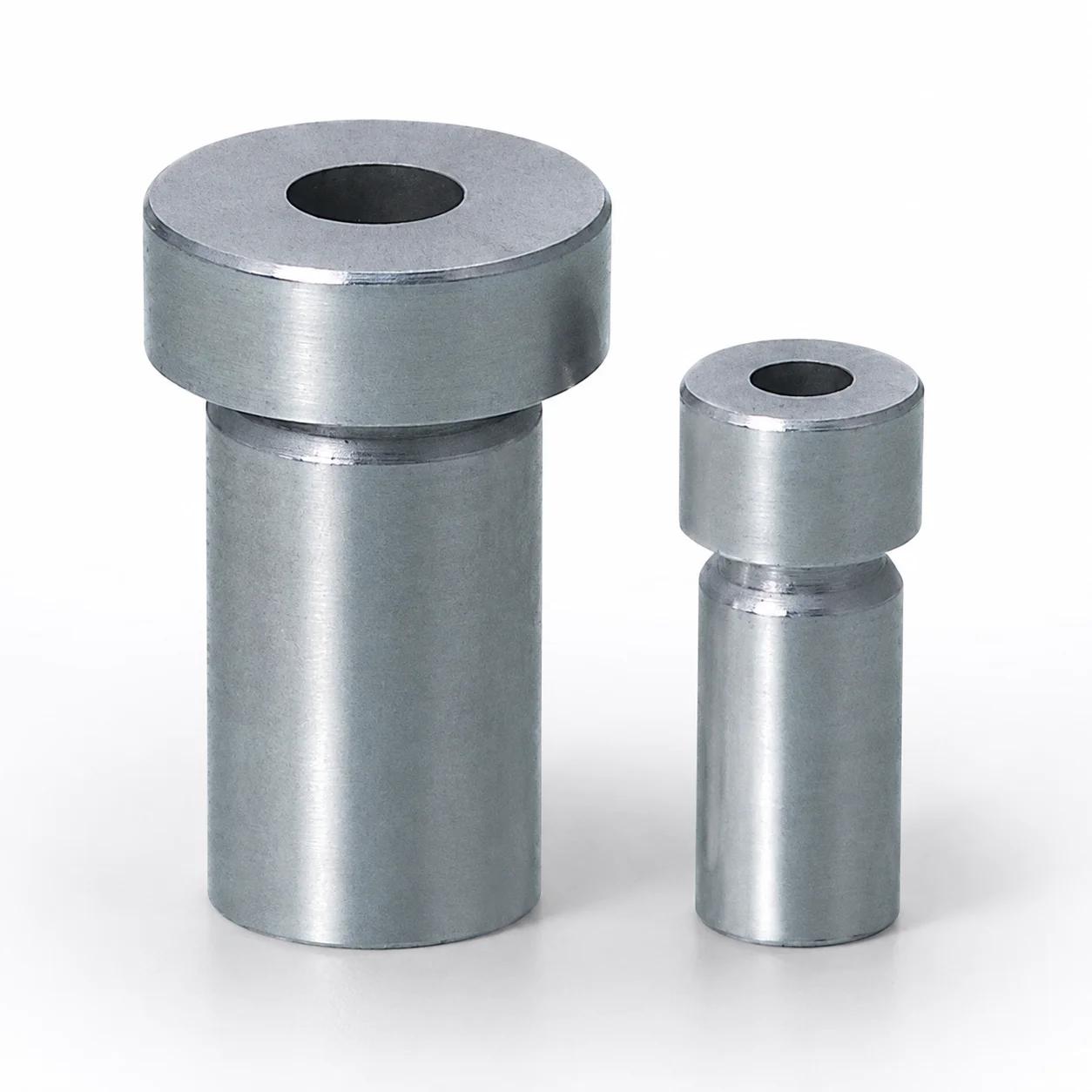
IRHB Inlay Core Pin Bushings Head
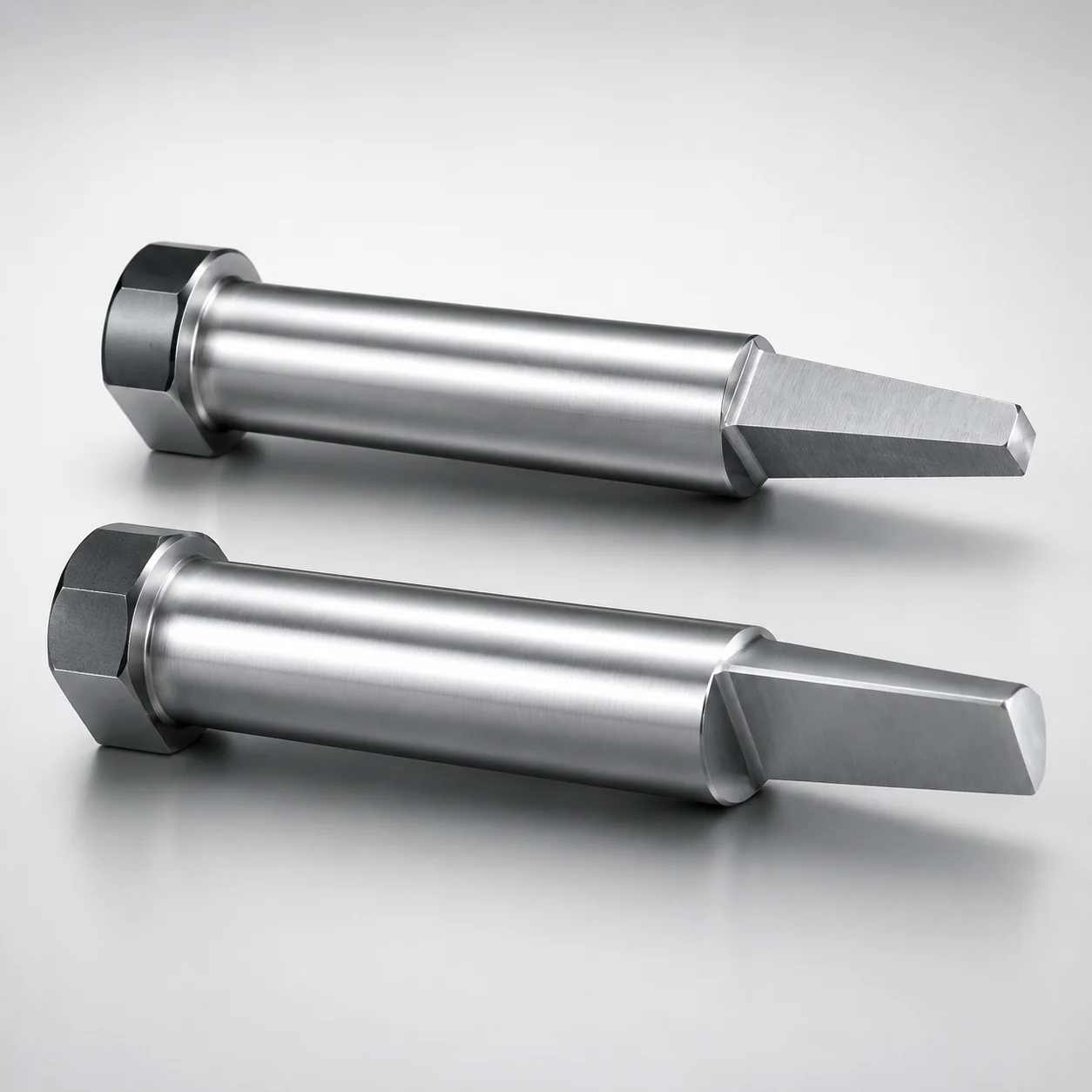
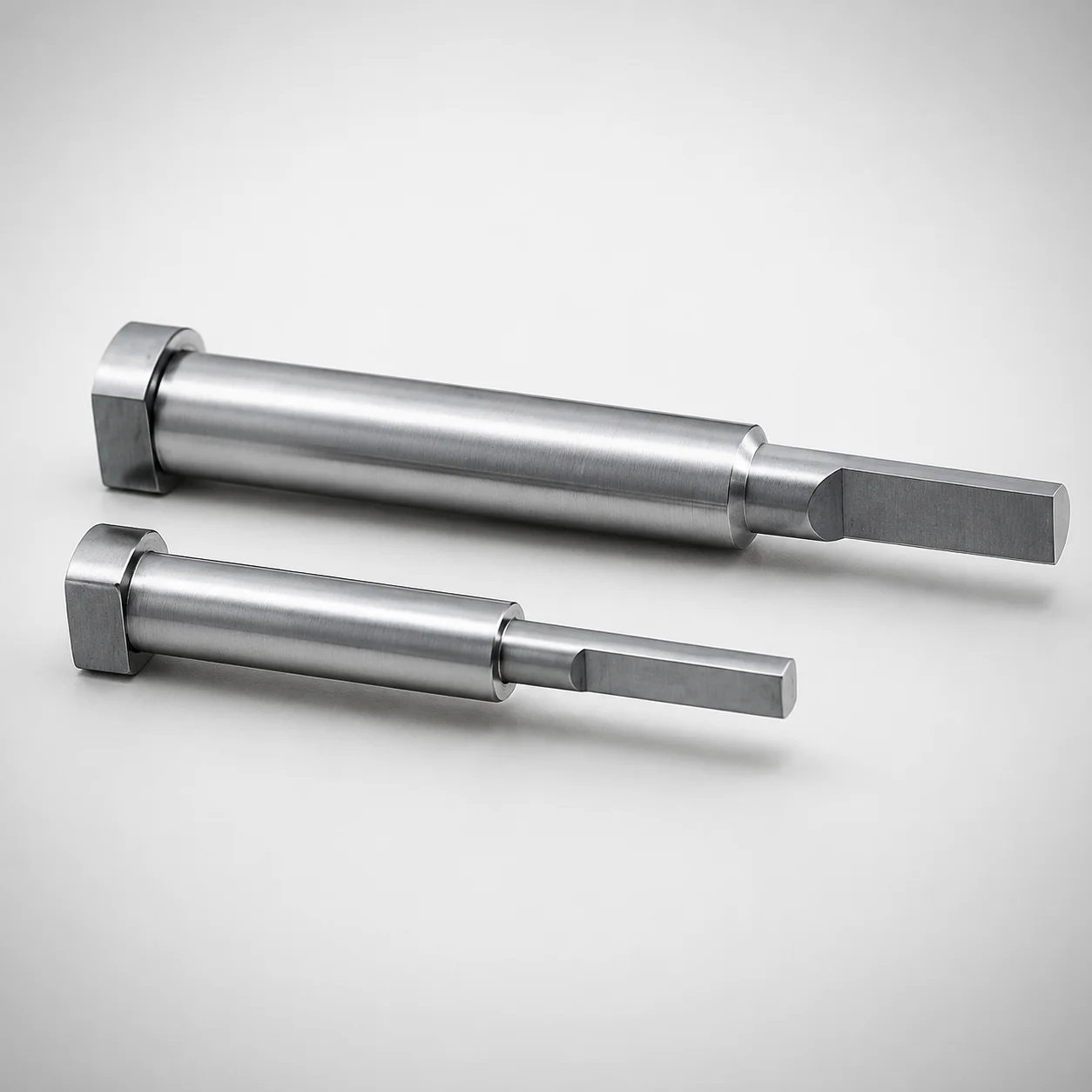
IRHB inlay core pin bushings head are engineered to improve alignment and reduce friction in precision die tooling. The robust design helps stabilize motion, protecting sensitive components under vibration and shock.
- IRHB bushing head type supports stable positioning for consistent core pin guidance
- Durable engineering construction resists wear while helping absorb shock and vibration
- Optimized fit reduces contact friction to maintain smooth machine operation
- Suitable for demanding molding and industrial environments requiring reliable inlay alignment
Specifications
6 configurations available
| D (Outer diameter) (mm) | L (L dimension) (mm) | P (Hole diameter) (mm) | type |
|---|---|---|---|
| 4 | 10 ~ 20 | 0.5 ~ 2 | - |
| 5 | 10 ~ 20 | 1.5 ~ 2.5 | - |
| 6 | 10 ~ 25 | 2 ~ 3 | - |
| 8 | 15 ~ 25 | 2.5 ~ 4 | - |
| 10 | 15 ~ 30 | 3 ~ 6 | - |
| 12 | 15 ~ 30 | 3.5 ~ 8 | - |
Product Guide
Application Scenarios+
This inlay core pin bushing head is used in precision injection mold tooling where a core pin must maintain stable alignment while sliding through a guide. It is commonly specified for boss-round inlay features to reduce frictional contact, helping ensure smooth motion during each press cycle.
- Automotive and appliance housings: In molds with long, slender core pins, the bushing head helps damp vibration and protect critical inserts from micro-misalignment under repeated shock loading.
- Electronic and connector housings: Tight guidance reduces rubbing at the interface, improving positional repeatability and reducing the risk of surface defects caused by stick-slip motion.
- High-cycle industrial parts: The design supports consistent core pin guidance, which is especially valuable when cycle times increase and wear control becomes critical.
Choose this variant when you need reliable alignment, reduced contact friction, and controlled behavior under vibration and shock in die tooling.
Material & Process Details+
The provided specifications for this IRHB inlay core pin bushing head list dimensional ranges only (D, L, and P), so the exact steel grade, hardness (HRC), heat-treatment state, and process route are not stated in the input data. As a result, material-related claims such as “quenched & tempered,” “nitrided,” or a specific alloy equivalency (e.g., SKD61 ≈ H13) cannot be verified from the supplied information.
- When selecting for wear and sliding performance, confirm the datasheet for the actual steel grade and surface treatment (e.g., nitriding or coating) that governs friction and galling resistance.
- Verify the target hardness (HRC) and the intended toughness balance—higher hardness improves wear resistance, while excessive hardness can reduce shock toughness.
- If multiple material options exist, compare their hardness and heat-treatment state against your cycle count and vibration/shock conditions.
Sizing & Selection Guide+
To select the correct bushing head size, match the outer diameter (D), length (L), and hole diameter (P) to the corresponding mold guide pocket and the core pin that passes through it.
- D (outer diameter) options (mm): 4, 5, 6, 8, 10, 12. Choose the D that fits the bushing location in the core housing with the required interference/clearance for stable guidance.
- L (length) ranges (mm): 10~20, 10~25, 15~25, 15~30. Select L to provide sufficient bearing length for alignment while avoiding interference with adjacent components.
- P (hole diameter) ranges (mm): 0.5~2, 1.5~2.5, 2~3, 2.5~4, 3~6, 3.5~8. P should be sized to the core pin diameter so the sliding interface maintains low friction without excessive looseness.
Confirm critical fits and tolerances with your core pin diameter spec; since no tolerance values are provided here, use your mold engineering standard to define the running clearance or transition fit.
Frequently Asked Questions
How do I choose the correct D (outer diameter) for mounting this bushing head in a boss-round inlay pocket?+
What L (length) range should I use to ensure stable core pin guidance without interference?+
How does the hole diameter P relate to the core pin size for low-friction operation?+
Is this bushing head intended to handle vibration and shock in high-cycle molds?+
What material selection details (steel grade and hardness) are required for wear vs. toughness trade-offs?+
Related Products
Need Custom Specifications?
Our engineering team can help with custom configurations, material selection, and volume pricing.