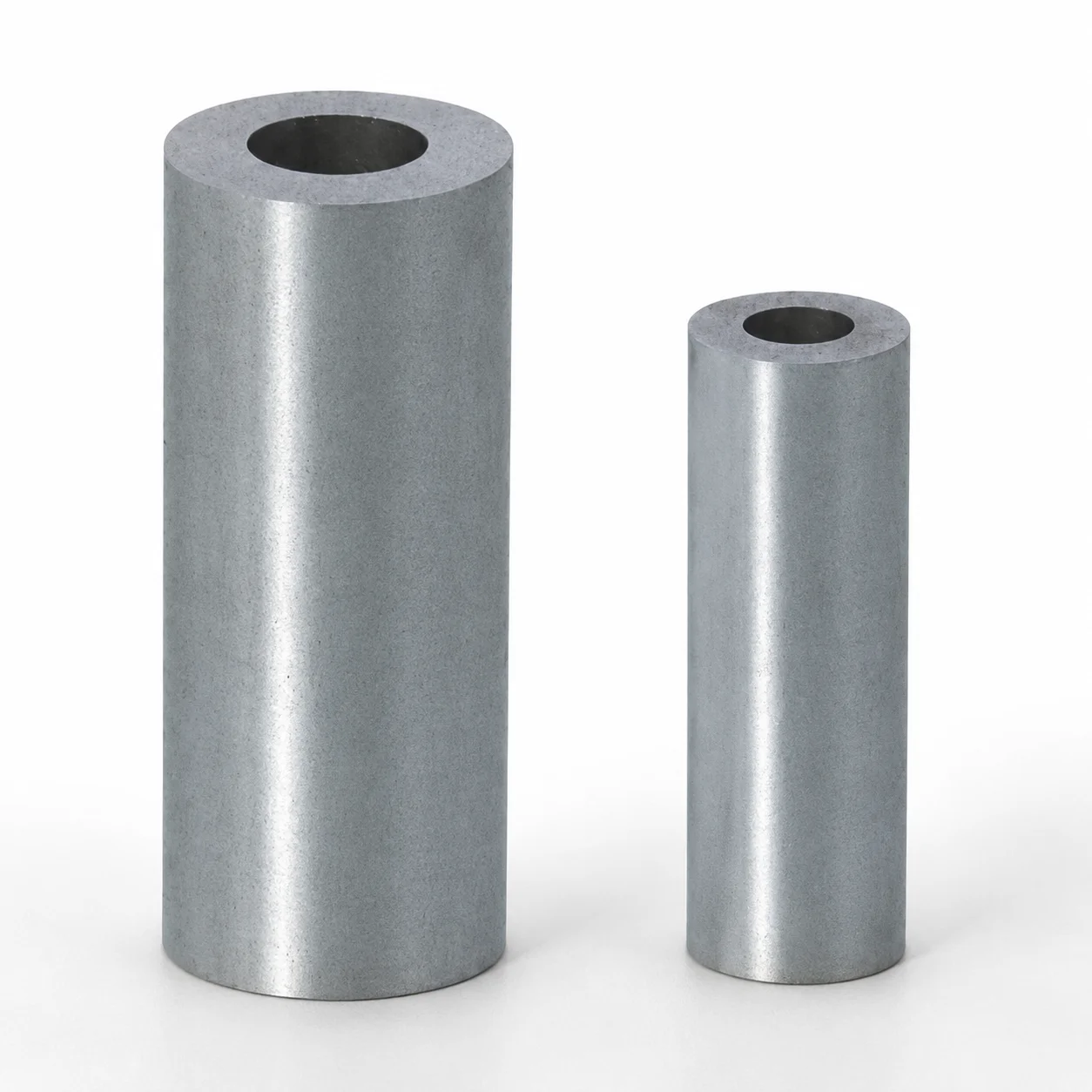
IRB Standard Straight Inlay Core Pin Bushings
Inlay core pin bushings - straight (IRB type) provide reliable alignment and support by maintaining a precise fit between the shaft and housing. They help reduce friction, limit wear, and support smooth rotational operation for industrial assemblies.
- Straight bushing geometry for stable shaft alignment in inlay core systems
- IRB type design supports durable operation under rotational contact
- Designed to minimize friction and wear, extending equipment service intervals
- Ideal for rotating mechanisms requiring smooth motion and low maintenance
Specifications
5 configurations available
| D (Outer diameter) (mm) | L (L dimension) (mm) | P (Hole diameter) (mm) | type |
|---|---|---|---|
| 4 | 8 ~ 20 | 0.5 ~ 2 | - |
| 5 | 8 ~ 20 | 1.5 ~ 2.5 | - |
| 6 | 10 ~ 25 | 2 ~ 3 | - |
| 8 | 15 ~ 25 | 2.5 ~ 4 | - |
| 10 | 15 ~ 30 | 3 ~ 6 | - |
Product Guide
Application Scenarios+
These IRB straight inlay core pin bushings are used in injection mold tooling wherever a rotating shaft must maintain a stable, repeatable fit against a housing. In automotive and appliance connector molds, they support low-friction rotation during actuation cycles, helping maintain alignment of moving features over long runs.
They are also well-suited for electrical connector and latch mechanisms that rely on smooth, controlled motion. The straight bushing geometry is engineered to keep shaft-to-housing concentricity during repeated contact, reducing wear-related drift in the rotating interface.
In industrial housings for gear or cam-based parts, the bushing’s inlay core application promotes consistent support while minimizing friction at the rotating contact. The IRB format is especially suited when designers want predictable alignment and reduced maintenance due to wear.
- Straight geometry supports stable shaft alignment in inlay core systems
- IRB type design helps limit friction and wear under rotation
Material & Process Details+
The provided product data does not specify a steel grade or heat-treatment state. Because inlay core pin bushings typically operate in sliding/rotating contact, select a tool steel grade and heat treatment that balances wear resistance with toughness to avoid chipping and deformation under cyclic loads.
Common approaches for bushing-style inserts include:
- Pre-hardened wear steels (easier to machine, moderate hardness) for assemblies where dimensional stability is prioritized.
- Quenched & tempered tool steels when higher strength and toughness are needed for repeated cycling.
- Nitriding (when specified) to improve surface wear resistance while keeping the core tougher, supporting longer service intervals.
For final selection, match hardness (often reported in HRC) and expected contact stress to the shaft diameter and operating friction requirements. If you need an HRC target, request the technical data sheet for this series code.
Sizing & Selection Guide+
To select the correct inlay core pin bushing, match the outer diameter (D) and length (L) to the inlay core pocket dimensions in the mold design. Your available ranges are D = 4, 5, 6, 8, 10 mm and L = 8–20, 10–25, 15–25, 15–30 mm (depending on the exact configuration).
Next, choose the hole diameter (P) to fit the mating shaft: P = 0.5–2, 1.5–2.5, 2–3, 2.5–4, 3–6 mm. This hole dimension sets the shaft-to-bushing interface clearance, which directly affects friction and wear.
- Use the selected D to ensure the bushing seats correctly in the core pocket without excessive play.
- Use L to cover the required support length along the shaft while avoiding interference with adjacent mold components.
- Confirm tolerances for P vs. shaft OD to balance smooth rotation and acceptable leakage/deflection.
If you have target clearance (or running fit class), select the P range accordingly; the dimensions listed above are the permissible values for this series.
Frequently Asked Questions
Which dimensions control the shaft-to-housing fit for IRB straight inlay core pin bushings?+
The fit is primarily controlled by the hole diameter (P) relative to the mating shaft diameter, using the available P ranges (0.5–2, 1.5–2.5, 2–3, 2.5–4, 3–6 mm). The bushing’s support seating is defined by the outer diameter (D) (4, 5, 6, 8, 10 mm) and length (L) (varies by configuration, e.g., 8–20 up to 15–30 mm).
How do I choose the correct outer diameter (D) and length (L) for the inlay core pocket?+
Select D first to match the core pocket geometry for stable seating: 4, 5, 6, 8, or 10 mm. Then choose L from the configuration’s allowed ranges (8–20, 10–25, 15–25, or 15–30 mm) to ensure the bushing provides the required support length without colliding with nearby mold features.
What hole diameter (P) range should I use to achieve low friction and reduced wear?+
Use the P range that corresponds to your shaft size, since P directly sets the internal diameter and therefore the running clearance. Available P options span 0.5–2 through 3–6 mm (depending on the selected configuration). Keep the clearance consistent with your expected deflection and lubrication/operation conditions.
Are these bushings limited to a specific material grade or heat treatment?+
The provided series information does not list a steel grade, hardness (HRC), or heat treatment (e.g., nitriding or quench & temper). For wear-critical rotating interfaces, you should confirm the technical data sheet for this series code to verify the material and heat treatment state before finalizing your design.
Do the IRB straight geometry and inlay core application affect alignment tolerances?+
Yes. The straight geometry is intended to maintain stable shaft alignment within the inlay core system, making the D and L seating dimensions important for concentric support. For precision alignment, ensure your core pocket dimensions properly locate the bushing, and verify P-to-shaft tolerances to control the rotating interface clearance.
Related Products
Need Custom Specifications?
Our engineering team can help with custom configurations, material selection, and volume pricing.