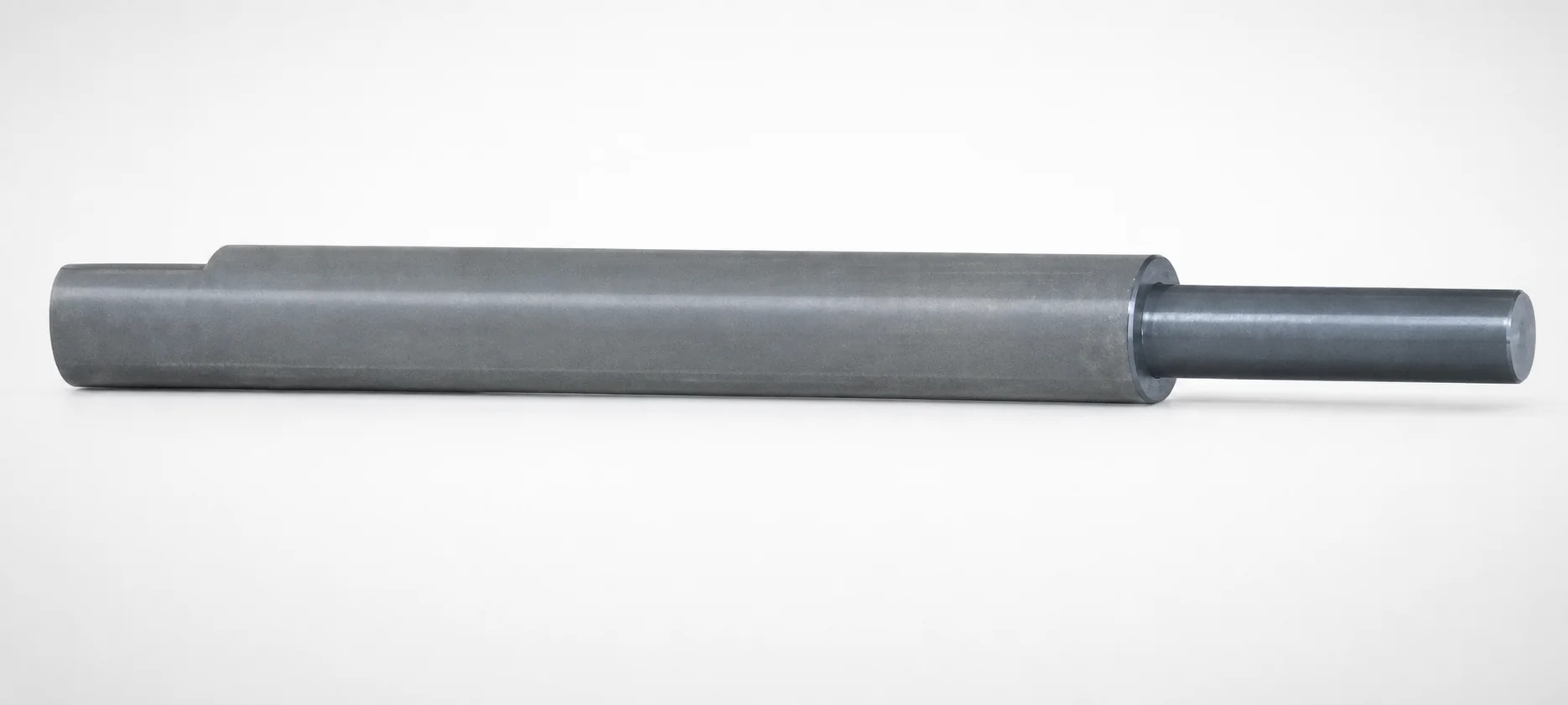
Inclined or Direct Push-Up Lifter Pins - Stepped
Inclined or Direct Push-Up lifter pins - Stepped provide reliable core engagement for consistent alignment and retention in modular mold assemblies. Their stepped design helps maintain stable positioning during operation, reducing misalignment risk in demanding production.
- Stepped geometry supports secure engagement and stable component alignment
- Designed for durable performance to reduce wear in repeated cycling
- Built for consistent loose core handling to support efficient modular assembly
- Suitable for industrial automation and machinery applications with strict positioning needs
Specifications
10 configurations available
| D (Applicable inclined pin diameter) (mm) | Applicable loose core part number | L (L dimension) (mm) | F (Length of inclined block side bearing bore length) (mm) | P (Inclined block side shaft diameter) (mm) | type |
|---|---|---|---|---|---|
| 12 | SCZN・SCZA | 100 ~ 800 | 6 ~ 36 | 6 ~ 9 | - |
| 16 | SCZN・SCZA | 100 ~ 800 | 8 ~ 52 | 8 ~ 13 | - |
| 20 | SCZN・SCZA | 100 ~ 800 | 10 ~ 68 | 10 ~ 17 | - |
| 30 | SCZN・SCZA | 100 ~ 800 | 10 ~ 108 | 15 ~ 27 | - |
| 8 | SCY | 100 ~ 600 | 4 ~ 24 | 4 ~ 6 | - |
| 10 | SCY | 100 ~ 800 | 5 ~ 32 | 5 ~ 8 | - |
| 12 | SCY | 100 ~ 800 | 6 ~ 36 | 6 ~ 9 | - |
| 16 | SCY | 100 ~ 800 | 8 ~ 52 | 8 ~ 13 | - |
| 20 | SCY | 100 ~ 800 | 10 ~ 68 | 10 ~ 17 | - |
| 25 | SCY | 100 ~ 800 | 12 ~ 88 | 12 ~ 22 | - |
Product Guide
Application Scenarios+
These stepped inclined/direct push-up lifter pins are used to control the vertical engagement of loose cores inside slide-core and loose-core mechanisms. In modular injection mold tooling, the pin’s stepped geometry helps maintain stable positioning as the core moves between open and closed states, supporting repeatable alignment and retention.
- Industrial automation and machinery housings: ideal when a loose core must be brought into precise position every cycle; the stepped design improves stability during retraction and push-up to reduce misalignment risk.
- Undercut features on plates and slide cores: suited for applications where reliable core engagement is required to form undercut geometry consistently without binding, especially in compact modular mold assemblies.
- Production lines requiring frequent modular swaps: supports efficient handling of loose cores by providing consistent engagement characteristics that help modular components assemble accurately.
Choose this variant when strict positioning and repeatable loose-core retention are critical to dimensional stability.
Material & Process Details+
The provided specifications describe the pin geometry and interfacing dimensions; no steel grade, heat-treatment condition, or hardness values are included in the product data. Therefore, the material properties, HRC targets, and specific heat treatment (e.g., quenched & tempered, nitrided) cannot be stated reliably for this exact SKU.
From a manufacturing standpoint, lifter pins for slide/loose-core systems are typically made from mold steels that balance wear resistance (to survive repeated cycling) with toughness (to resist chipping under load). If your application includes high abrasion or high cycle counts, confirm the available material grade and any surface treatments with your supplier before finalizing the design.
- Confirm key specs: steel grade, hardness (HRC), and whether any nitriding/coating is specified for 110200061260.
- Trade-off note: higher hardness improves wear resistance but may reduce toughness if not tempered appropriately—verify for your load and impact conditions.
Sizing & Selection Guide+
Select lifter pins by matching both the inclined/direct pin diameter and the core interface geometry to your slide-core/loose-core design.
- Diameter (D): choose from 8 ~ 30 mm based on the required engagement strength and clearance in the loose-core mechanism.
- Pin length (L): select from 100 ~ 800 mm (or 100 ~ 600 mm depending on the applicable configuration). Ensure L covers the full stroke region between start positioning and full push-up engagement.
- Inclined block side bearing bore length (F): set to 4 ~ 12 mm to match the bearing surface length in the inclined block for stable guidance.
- Inclined block side shaft diameter (P): choose 4 ~ 15 mm to match the mating bore/shaft in the block, maintaining proper fit without excessive play.
Because this SKU also specifies applicable loose core part families (SCZN/SCZA and SCY), confirm the correct loose-core part number first, then lock D, L, F, and P to the mating mechanism. Tolerance/fit guidance is not provided in the data, so use your standard for clearance to prevent binding and ensure repeatable alignment during cycling.
Frequently Asked Questions
How do I choose the correct inclined pin diameter (D) for this stepped push-up lifter pin?+
Use the specified D range of 8 ~ 30 mm and select the diameter that matches the mating space and required engagement stability for your loose-core mechanism. Since the product is intended for SCZN・SCZA and SCY loose core families, verify the clearance and interfacing features for the specific loose core part number before finalizing D.
What length options (L) are available, and how should I verify stroke coverage in the mold?+
The pin length (L) is specified as 100 ~ 800 mm, with an additional configuration range of 100 ~ 600 mm indicated in the data. Confirm that the selected L length covers the full movement window from the initial position through complete push-up engagement, without interference in the open/close cycle.
How do the bearing bore length (F) and block side shaft diameter (P) affect guidance and alignment?+
The interface dimensions are F = 4 ~ 12 mm and P = 4 ~ 15 mm. Proper matching helps the pin guidance remain stable during cycling, which supports consistent loose-core alignment and retention. If these values are undersized or mismatched, you risk increased play or binding, which can degrade positioning accuracy.
Which loose core part numbers are compatible with this lifter pin series?+
The data lists compatible loose core part families as SCZN・SCZA and SCY. When designing the modular assembly, select the loose core first and then choose D, L, F, and P according to the mating block interface for that specific core type.
Does the stepped design change how I should size the mechanism for undercut/loose-core retention?+
The stepped geometry is intended to support secure engagement and stable positioning during push-up and retention cycles. Practically, this means you should ensure the stepped engagement region has adequate space and that the guidance interfaces (F and P) provide stable alignment throughout the motion, so the loose core remains consistently retained during production.
Related Products
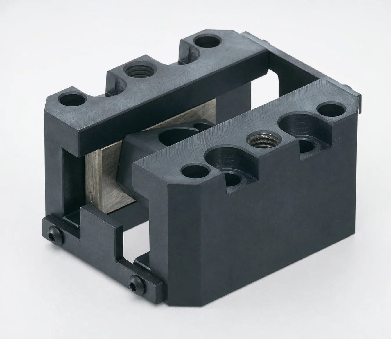
SCZN Oil-Free Slide Units for Loose Core
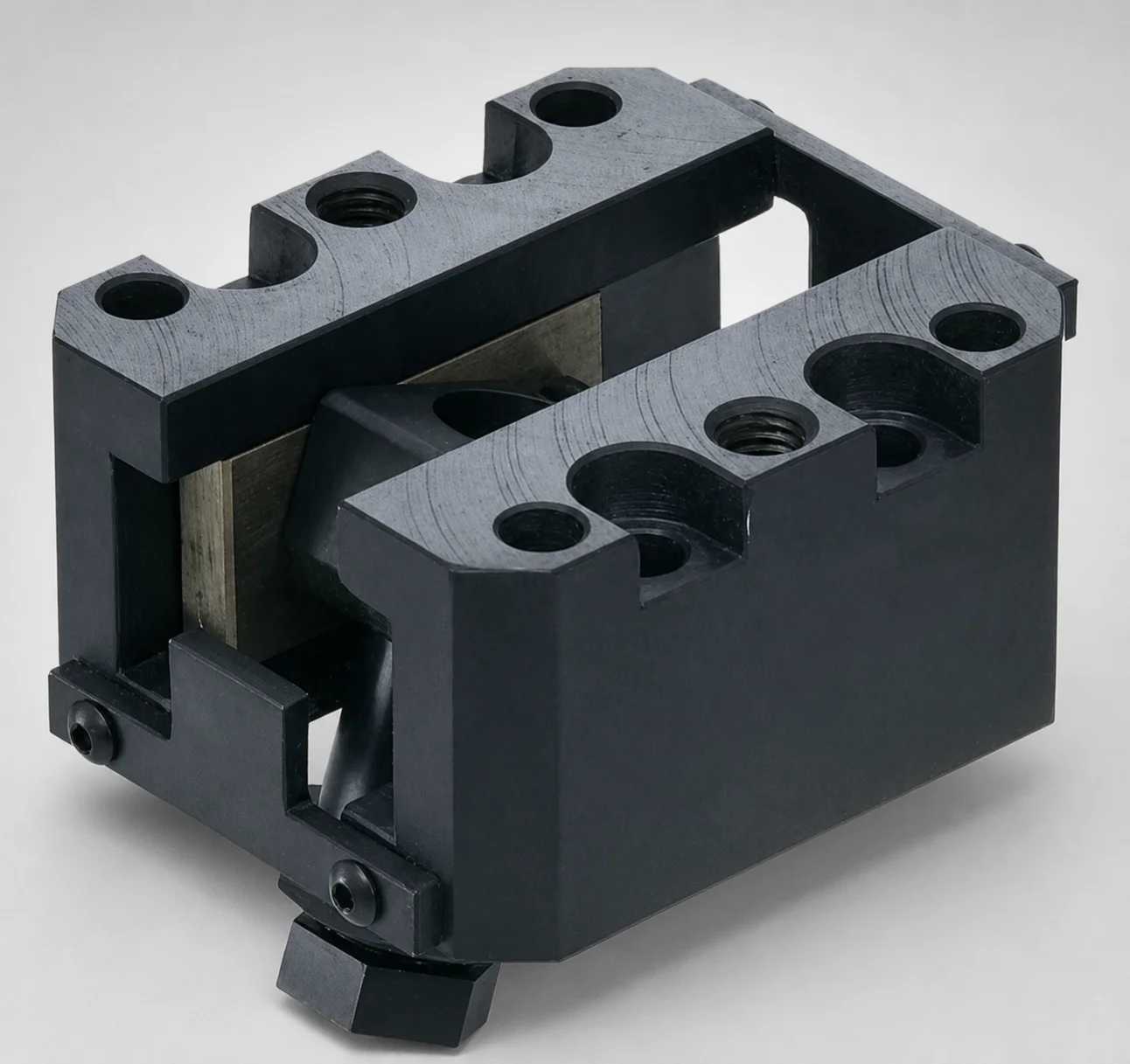
SCZA Oil-Free Slide Units for Loose Core - Inclined Pin Height Fine Tuning
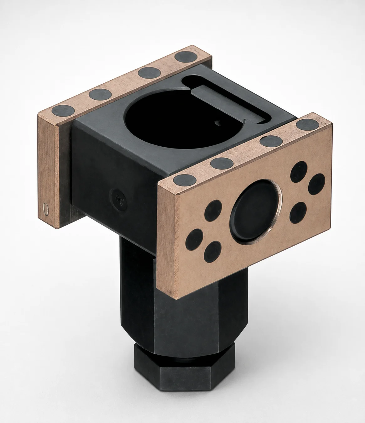
SCZAP Oil-Free Slide Inclined Pin Holders for Loose Core
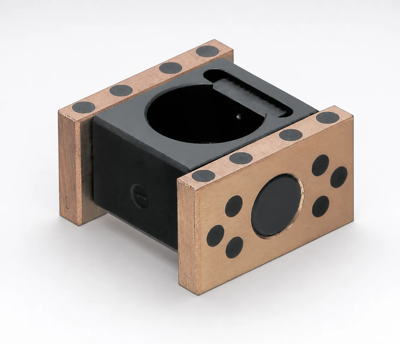
SCZNP Type Oil-Free Slide Inclined Pin Holders for Loose Core
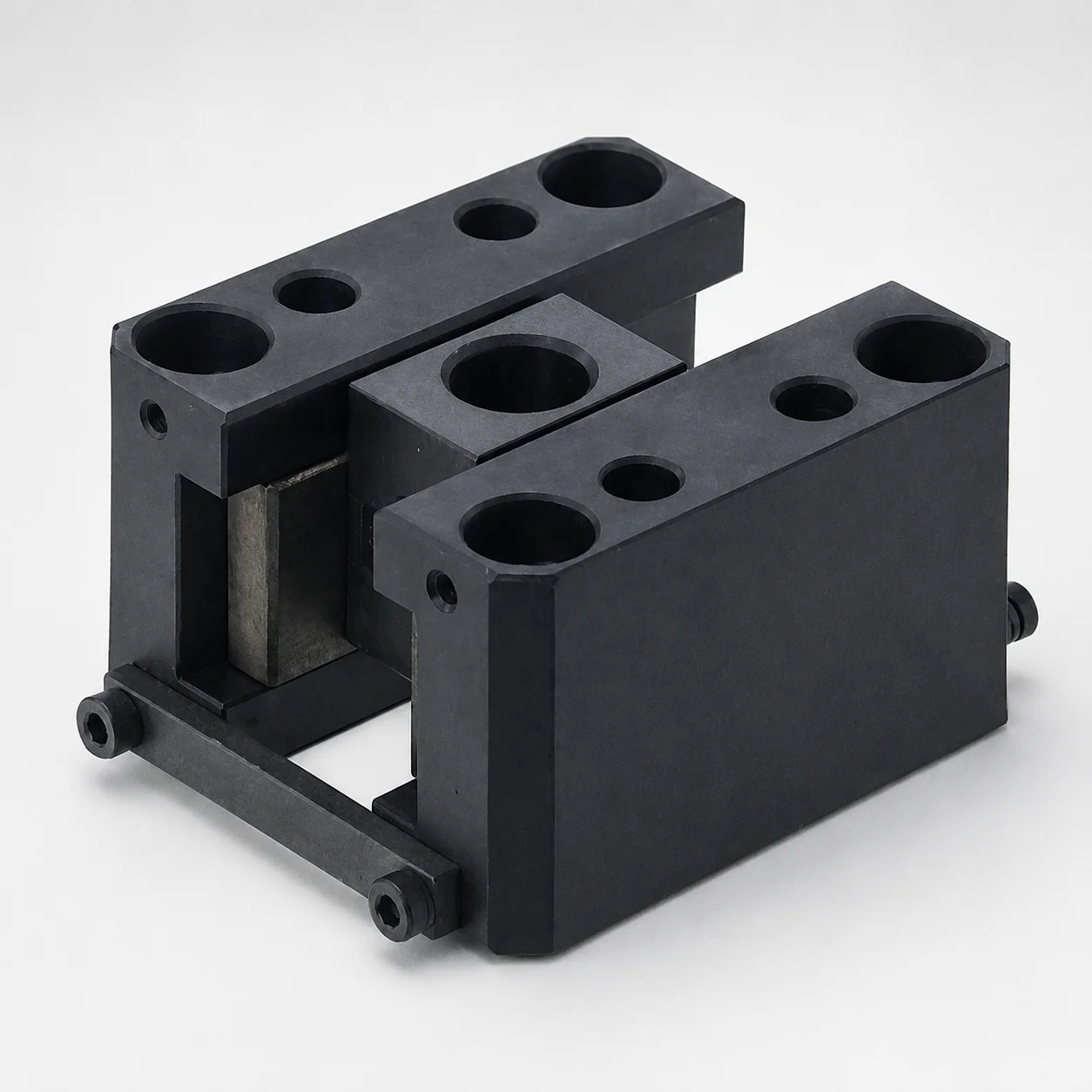
SCY Type Oil-Free Slide Units for Loose Core
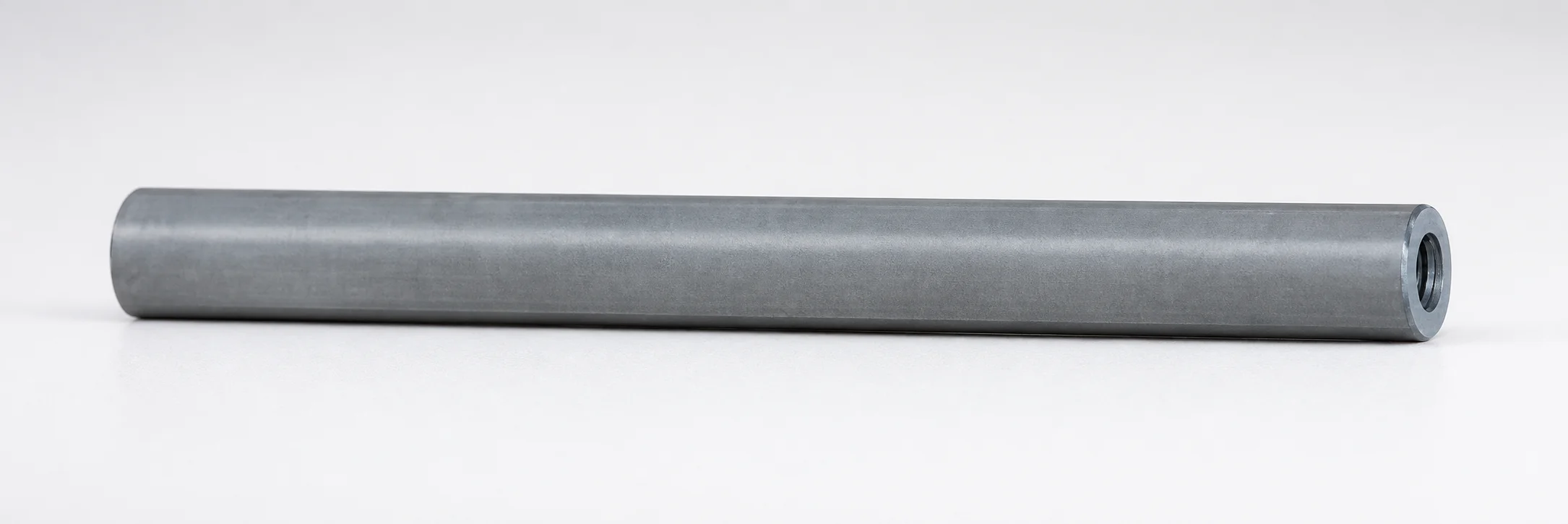
Inclined or Direct Push-Up Lifter Pins - Both Ends Tapped
Need Custom Specifications?
Our engineering team can help with custom configurations, material selection, and volume pricing.