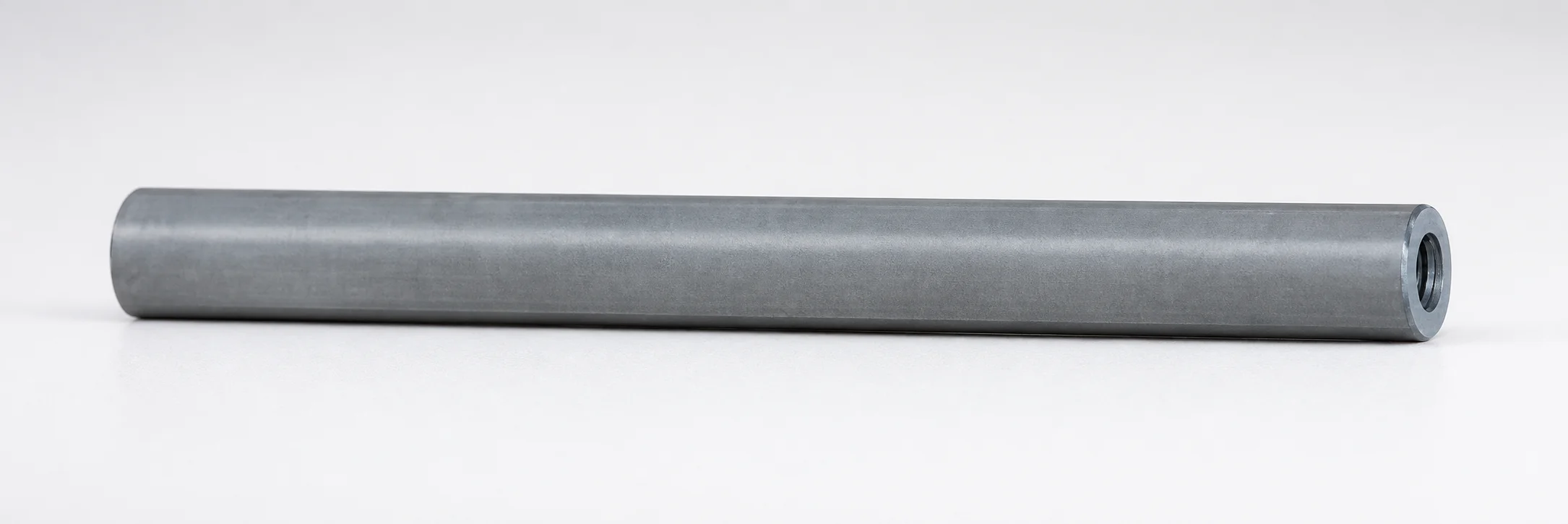
Inclined or Direct Push-Up Lifter Pins - Both Ends Tapped
Inclined or Direct Push-Up Lifter Pins - Both Ends Tapped (loose core pins) provide dependable fastening and alignment for lift-up mechanisms across varied assembly needs. They help maintain positional stability during manufacturing and installation.
- Both ends tapped design supports secure fastening and accurate alignment
- Used in loose core assemblies to preserve structural integrity during cycling
- Available for a wide D range (applicable inclined pin diameter) to match assembly requirements
- Tap sizes include Compact and Normal for compatibility with different tooling interfaces
Specifications
12 configurations available
| D (Applicable inclined pin diameter) (mm) | Tap size | L (L dimension) (mm) | type |
|---|---|---|---|
| 12 | Compact | 100 ~ 800 | - |
| 16 | Compact | 100 ~ 800 | - |
| 20 | Compact | 100 ~ 800 | - |
| 25 | Compact | 100 ~ 800 | - |
| 30 | Compact | 100 ~ 800 | - |
| 8 | Normal | 100 ~ 600 | - |
| 10 | Normal | 100 ~ 800 | - |
| 12 | Normal | 100 ~ 800 | - |
| 16 | Normal | 100 ~ 800 | - |
| 20 | Normal | 100 ~ 800 | - |
| 25 | Normal | 100 ~ 800 | - |
| 30 | Normal | 100 ~ 800 | - |
Product Guide
Application Scenarios+
Inclined or direct lift-up mechanisms in injection mold tooling often rely on stable, repeatable movement during opening and closing. These push-up lifter pins—secured using tapped ends—are well-suited for loose core assemblies where positional stability directly impacts part geometry.
- Automotive and precision multi-cavity molds: Use the pinned lift-up setup to ensure consistent core rise, helping maintain shut height and reducing alignment drift over repeated cycles.
- Electronics housings and connector tooling: The tapped-both-ends fastening supports accurate registration of slide-core/loose core components, improving dimensional consistency for fine ribs and snap-fit features.
- Thin-wall or high-repeat production molds: Reliable fastening helps maintain structural integrity during cycling, which is critical when lift-up accuracy affects uniformity and finish.
The both-ends tapped variant simplifies installation and alignment by providing secure attachment points, making it a practical choice for assemblies that must remain stable under repeated actuation.
Material & Process Details+
The provided product specifications describe dimensional ranges and tap formats but do not include the steel grade, heat-treatment state (e.g., quenched & tempered, nitrided), or target hardness (HRC). As a result, material-property claims such as wear resistance, toughness, or hardness trade-offs cannot be stated from the supplied data.
For engineering selection, confirm the actual pin steel grade and heat-treatment condition from the manufacturer’s material certificate or technical drawings before specifying for your cycle rate, abrasive content, and expected wear mechanisms.
- Hardness (HRC): Not provided in the input data—verify before use.
- Wear/toughness balance: Not provided—depends on the confirmed steel and treatment.
- Tap size options: The input data specifies Compact and Normal tap sizes, which affect interface compatibility rather than material performance.
If multiple material options exist in your sourcing channel, compare them using hardness, corrosion resistance, and expected surface wear under your tooling conditions.
Sizing & Selection Guide+
Select the push-up lifter pin dimensions to match the cavity/core lift path and the mechanical interface used to secure the pin ends.
- Inclined/direct pin diameter (D): Choose D in the range 8 ~ 30 mm. This diameter must fit the corresponding bore/guide and maintain the required clearance for smooth lift-up without binding.
- Pin length (L): Use the provided options: 100 ~ 800 mm or 100 ~ 600 mm depending on the configured product variant. Ensure L covers the full required stroke and engagement length within the loose core assembly.
- Tap size compatibility: Match the Compact vs Normal tap size to your fastening hardware and tooling interface so the ends can be secured reliably.
Because no tolerance values are provided, keep engineering allowances in mind for installation and alignment. The tapped ends require that the mating components are threaded correctly to avoid misalignment that can affect core rise accuracy.
Frequently Asked Questions
Which diameter range (D) is supported for these inclined/direct push-up lifter pins?+
What are the available length (L) ranges, and how do I choose the correct stroke coverage?+
How do Compact vs Normal tap sizes affect compatibility in loose core assemblies?+
Are these pins intended for direct lift or inclined lift-up mechanisms?+
Do I need specific material data (steel grade/heat treatment) to finalize the pin selection?+
Related Products
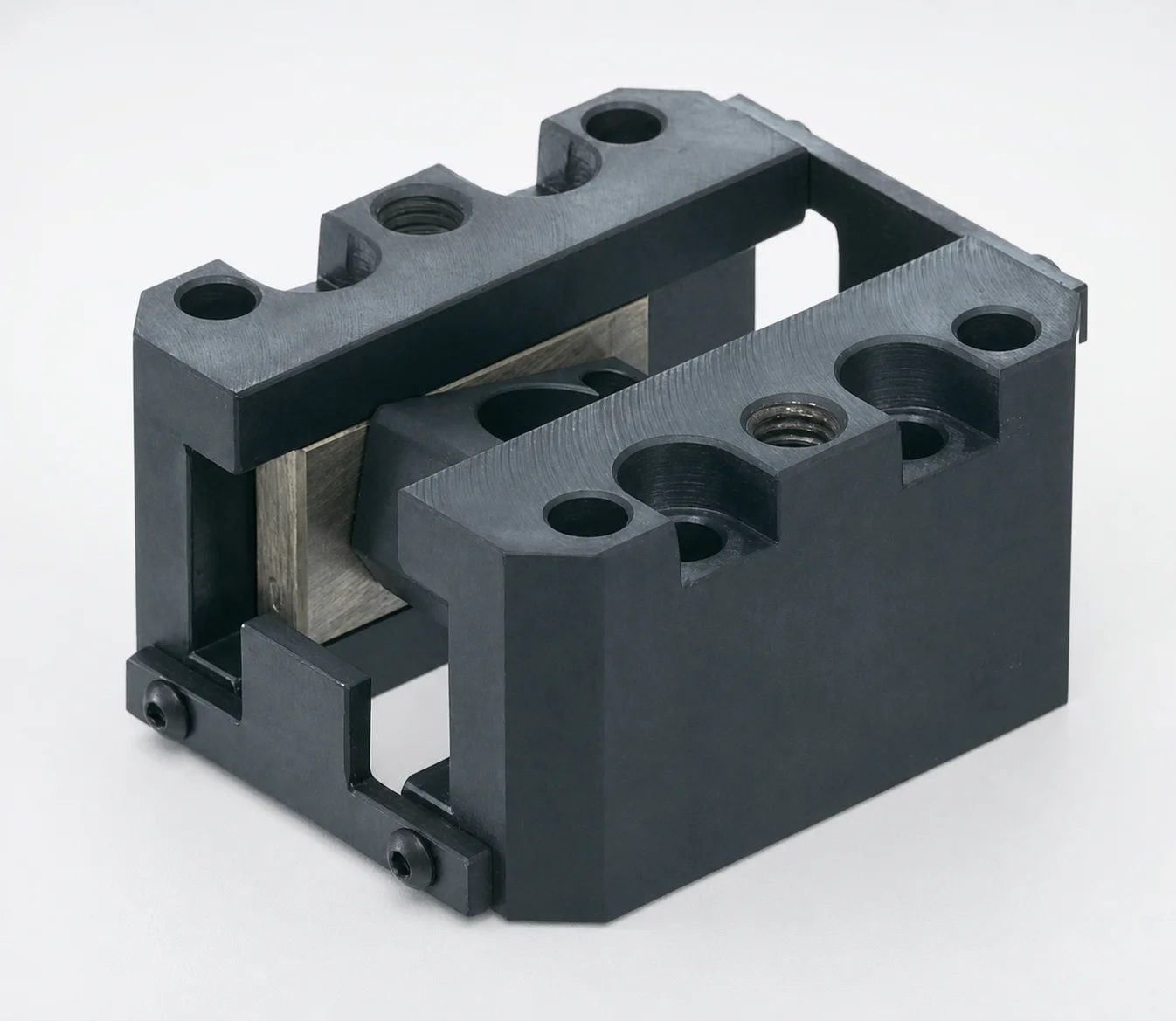
SCZN Oil-Free Slide Units for Loose Core
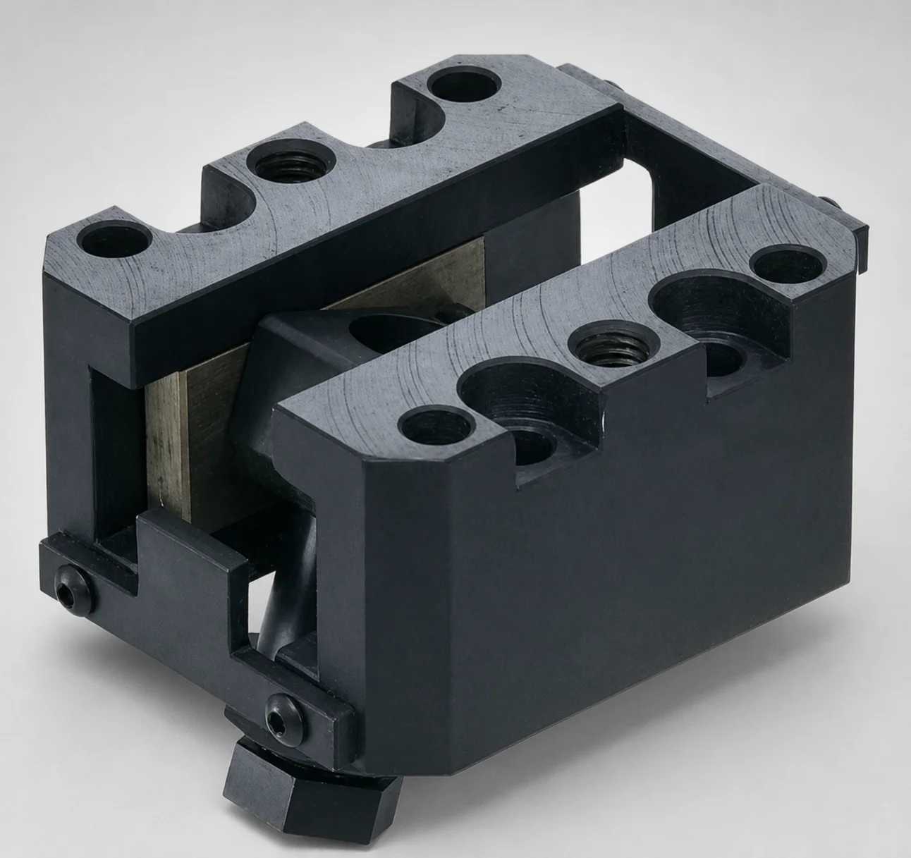
SCZA Oil-Free Slide Units for Loose Core - Inclined Pin Height Fine Tuning
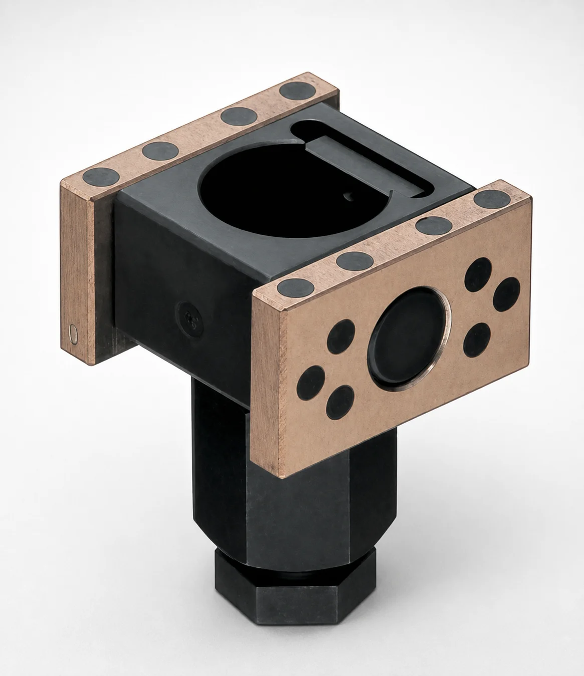
SCZAP Oil-Free Slide Inclined Pin Holders for Loose Core
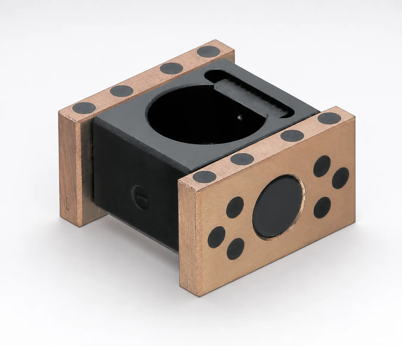
SCZNP Type Oil-Free Slide Inclined Pin Holders for Loose Core
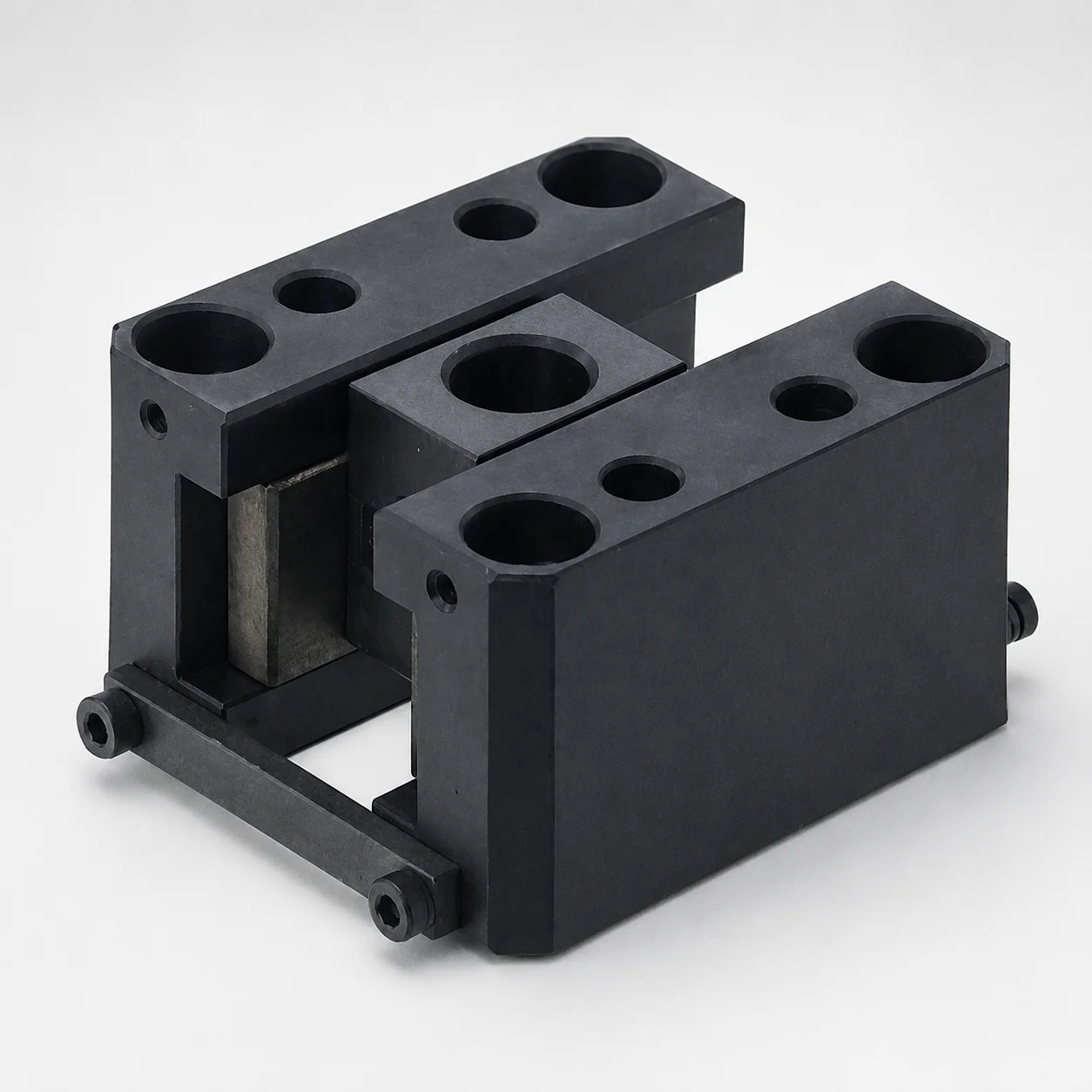
SCY Type Oil-Free Slide Units for Loose Core
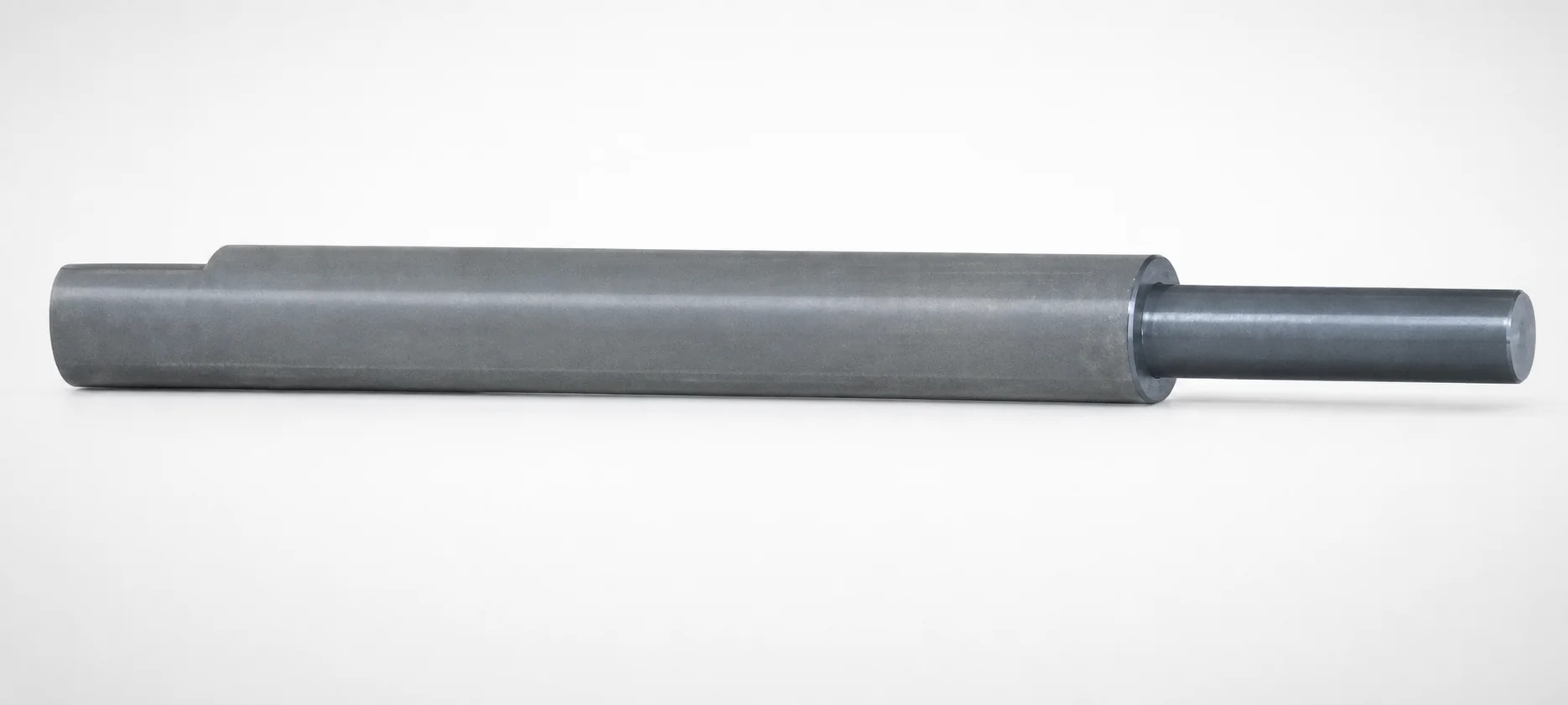
Inclined or Direct Push-Up Lifter Pins - Stepped
Need Custom Specifications?
Our engineering team can help with custom configurations, material selection, and volume pricing.